
Brian Slovick, Josh Hellhake. Inverse design of invisibility cloaks using the optical theorem[J]. Photonics Research, 2022, 10(4): 974
- Photonics Research
- Vol. 10, Issue 4, 974 (2022)
Abstract
1. INTRODUCTION
The development of invisibility cloaks is a longstanding goal in electromagnetics [1–7]. An object that is invisible to electromagnetic waves would have widespread application in both military and commercial systems. At radio frequencies, cloaked objects have a zero radar cross section [8,9], while optical displays with low scattering and reflection provide an improved viewing experience [10,11]. It has also been proposed that cloaked sensors may provide enhanced sensitivity because of a reduced interaction with the environment [12–16].
More recently, the development of metamaterials and metasurfaces has expanded the design space to include materials with negative refractive indices and plasmonic properties [17]. Materials with negative indices can be used with transformation optics to design electromagnetic cloaks [18–20], and several implementations have been demonstrated [21–23]. Transformation optics has the considerable advantage of imposing no limitations on the size and shape of the object. However, the designs often require complex anisotropic materials with negative refractive indices, which inevitably suffer from large absorption losses and dispersion [24]. Carpet cloaks can be designed using materials with positive isotropic indices [22,25], but they do not provide invisibility.
Scattering cancellation is an alternative method to achieve invisibility [26]. Of course, antireflection coatings are used throughout industry to reduce reflection by planar surfaces [10,11]. For nonplanar structures, such as spheres and cylinders, multilayered designs involving dielectric [27,28] and plasmonic materials [29,30] have been proposed. However, these designs are either limited to simple shapes or suffer from large absorption losses [24]. Metasurfaces with tailored surface impedance or mantle cloaks have been proposed as an alternative to thicker, multilayer designs [31–34]. However, their application is limited to subwavelength objects. Therefore, a more generalized design approach applicable to objects of any size and shape that does not involve plasmonics or materials with negative indices would be a significant advance.
Sign up for Photonics Research TOC. Get the latest issue of Photonics Research delivered right to you!Sign up now
In recent years, inverse methods have become the predominant approach in photonic design [35–43]. Broadly described, inverse design is the optimization of an objective function with respect to the structure or material properties. Inverse design has been used to optimize photonic circuits [35–37] and nanophotonic resonant structures [38–42]. The key to developing an effective inverse design algorithm lies in the definition of the objective function. For instance, to design highly scattering structures, a suitable objective function is the determinant of the wave operator defining the poles of the scattering matrix [40]. On the other hand, nonscattering structures can be designed by minimizing the scattering cross section [44,45]. However, the need to calculate the cross section from the scattered field for all angles at each step in the optimization poses a computational challenge, and also limits the scale and type of objects that can be optimized.
In this paper, we develop a more efficient optimization method to design unidirectional invisibility cloaks. Our inverse design approach is based on minimizing the forward scattering amplitude, which by the optical theorem is equal to the total cross section [46,47]. The use of the optical theorem circumvents the need to integrate the scattered fields over an angle by evaluating the cross section from the forward scattering amplitude alone, thus providing a simpler, more computationally efficient algorithm. Our method is completely general and makes no assumptions about the size, shape, or composition of the object, though large objects still present a computational challenge. For demonstration, we apply it to design unidirectional gradient-permittivity cloaks to minimize scattering from metallic targets of different sizes and shapes. We show that orders of magnitude reductions in the cross section are achievable with subwavelength coatings. The ease and effectiveness of our approach enables the optimization of large-scale nonscattering structures and invisibility cloaks.
2. APPROACH
Consider an object in free space with isotropic relative permittivity . The electric field scattered by the object is obtained by solving the time-harmonic Maxwell’s equation with the Silver–Müller radiation boundary condition. The solution for the scattered field is [2,48–50]
The most computationally intensive calculation in Eq. (9) is the matrix inversion, and the desire is to minimize the number of matrix inversions required to minimize the scattering cross section. Unfortunately, integral equations give rise to dense matrices, so sparse matrix techniques such as a conjugate gradient and its derivatives cannot be directly applied without introducing sparsifying approximations [51,52]. Proceeding with a conventional gradient descent, we must evaluate the derivative of the objective with respect to , which involves a numerical evaluation of the Jacobian and an additional matrix inversion. Fortunately, since the objective function has an analytical form, we can obtain a closed-form expression for the Jacobian as
We tested this methodology using MATLAB on a standard PC, and the memory limitations provided a practical limitation on the size of the matrix that could be inverted, thus limiting the size of the scattering object compared to the wavelength. To relax this size limitation, we tested the methodology using a 2D object and transverse electric field. In this case, Eq. (1) reduces to a scalar equation for the transverse component, where the integral is over two dimensions and Green’s function is the scalar 2D Helmholtz kernel [3,51]
3. RESULTS
To test this methodology to design unidirectional nonscattering objects, we considered various cases of an optimized cloak applied to a metal rod. The model was parameterized with the dimensions of the metal rod, cloak, and grid elements all defined relative to a wavelength . The permittivity of the metal rod was chosen to be , corresponding to a highly conductive metal. Although we quickly found that neither the resulting cloak design nor the scattering cross-section reduction was highly dependent on the exact permittivity of the rod as long as it was sufficiently conductive, we did find that using realistic metal permittivity values at optical wavelengths resulted in significant absorption cross section values that put a lower bound on the total cross-section reduction. Using a highly conductive rod minimizes absorption in the rod so the scattering cross-section reduction is equivalent to the total cross-section reduction as computed using the optical theorem. Figure 1 shows the model setup, which in this case included the highly conductive metal cylinder with a radius, a thick cloak, and a grid size of (), resulting in 1804 grid elements across the rod and cloak. The plane wave was incident in the direction with a polarization parallel to the length of the rod. The top row of plots [Fig. 1(a)] shows the permittivity distribution with no cloak as well as the real part of the scattered and total field inside and outside the rod calculated using the discrete integral form of Eqs. (7) and (8). The total cross section of the uncloaked rod calculated using Eq. (9) is . As expected, the rod strongly scatters the incident wave, creating interference patterns throughout the region around the rod.
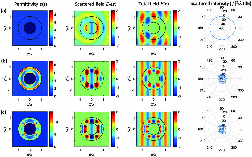
Figure 1.Relative permittivity, scattered fields, total fields, and scattered intensity for a
The second and third rows [Figs. 1(b) and 1(c)] show the results of optimizing the cloak using the fmincon function in Matlab. The fmincon function was used to vary the permittivity at each grid element in the cloak to minimize the cross section as calculated using Eq. (9). The optimization was run with an allowed permittivity range of 1–16, the upper bound corresponding to germanium, and the gradient of the cross section was supplied to minimize the computational time required; otherwise, fmincon used the default algorithm and convergence criteria. Because optimization algorithms such as fmincon require an initial seed value for the optimization, we defined the initial shell permittivity to be a uniform value throughout the cloak. The results in the second row were for a uniform seed value of 3, and the optimized cloak permittivity distribution ranges from 1 to 8.7 with an expected mirror symmetry around the axis that was not imposed in the optimization algorithm. This design shows extremely small, scattered field intensities around the cloak, resulting in a total field nearly identical to the incident plane wave. Calculating the scattering cross section with the cloak using Eq. (9) gives a value of , a reduction factor of approximately 4,000, or 36.0 dB. This strong reduction in the scattering amplitude is shown in the final column of Fig. 1(b). These results confirm the effectiveness of this methodology and were generated in only a few minutes of computational time. The results in the third row [Fig. 1(c)] used the same algorithm but with an initial seed permittivity of 5. With this higher seed value, the maximum permittivity in the cloak increases to 13.5 and the permittivity has sharper gradients within the cloak. Despite the very different design, the cross section reduction is just as effective as the previous design, with a total cross section of , a reduction factor of 37.0 dB. Comparing these results to those in Fig. 1(b) shows the importance of the initial seed in the optimization and points to the need for global optimization algorithms in future work.
Having generated these promising results for a relatively thick cloak, we then performed similar optimizations with half the cloak thickness, or . While the structure size was reduced, we maintained a grid size of to ensure an accurate comparison with the results in Fig. 1. In this case, shown in Fig. 2, we observed a much greater difference in the cross-section reduction between the two optimization seeds. The cross-section reduction for the seed was only 11.5 dB, whereas the reduction with the seed was 36.6 dB, which is comparable to the results with the thicker cloak.
![]()
Figure 2.Relative permittivity, scattered fields, total fields, and scattered intensity for a
Next, we performed an additional cloak design for a metal rod with an elliptical cross section to show the applicability to general shapes aside from an ideal cylinder. In this case, the metal rod was an ellipse with a major axis length and a minor axis length, with the major axis rotated 45° off the incident field. The cloak was thick around the elliptical rod, and the grid size remained . The optimization results in this case, shown in Figs. 3(b) and 3(c), gave cross-section reduction factors of 35.8 dB for the seed and 28.0 dB for the seeds.
![]()
Figure 3.Relative permittivity, scattered fields, total fields, and scattered intensity for an elliptical metal rod with
Finally, we evaluated the sensitivity of an optimized cloak to the wavelength and the angle of incidence. Since the optimization was performed for a single angle of incidence and wavelength, the design is expected to be sensitive to variations in these parameters. Figures 4(a) and 4(b), respectively, show the wavelength and angle of incidence dependence of the uncloaked cylinder in Fig. 1(a) and the cloaked design in Fig. 1(b). As expected, the cross section of the optimized cloak is a minimum at the design wavelength () and an angle of incidence of 0°. The scattering cross section of the cloaked structure is reduced over a 12% spectral bandwidth and is an order of magnitude lower over a 3.5% spectral bandwidth. With respect to the angle of incidence, the cross section of the cloak design is reduced over a 54° angular range and reduced by an order of magnitude over 14°.
![]()
Figure 4.Cross section of the uncloaked structure in Fig.
Overall, these cases all show that the optical theorem methodology to design unidirectional invisibility cloaks is highly effective. In all cases examined here, the optimization of the cloak resulted in cross sections that were a small fraction of the initial metal rod, and the optimization was completed in 5 min or less using a standard PC. Areas for future work include using a global optimizer to get the best design possible for a given set of permittivity constraints. This should be possible using the global optimization functions in MATLAB. We also plan to explore omnidirectional and broadband cloak designs using a multiobjective optimization to simultaneously minimize the cross section at several wavelengths and angles.
4. SUMMARY
We developed and applied an inverse optimization method to design unidirectional invisibility cloaks. The method is based on minimizing an objective function equal to the forward scattering amplitude of the cloaked object, which by the optical theorem is equivalent to the total cross section. The use of the optical theorem greatly simplifies the optimization since only the forward scattering amplitude must be calculated at each iteration, in contrast to the traditional approach based on integrating the amplitude over an angle. Using a nonlinear least squares gradient descent, we applied the method to design several unidirectional gradient-permittivity cloaks to reduce scattering from metallic circular and elliptical cylinders. We believe our generalized approach provides a simple, effective design tool that enables the optimization of large-scale nonscattering structures and invisibility cloaks.
References
[1] A. Devaney. Mathematical Foundations of Imaging, Tomography and Wavefield Inversion(2012).
[2] D. Colton, R. Kress. Inverse Acoustic and Electromagnetic Scattering Theory(2012).
[3] M. Fiddy, R. Ritter. Introduction to Imaging from Scattered Fields(2014).
[4] E. Wolf, T. Habashy. Invisible bodies and uniqueness of the inverse scattering problem. J. Mod. Opt., 40, 785-792(1993).
[5] R. Rumpf, M. Fiddy, M. Testorf. Design of generalized invisible scatterers. Opt. Express, 15, 4735-4744(2007).
[6] B. Hoenders. Existence of invisible nonscattering objects and nonradiating sources. J. Opt. Soc. Am. A, 14, 262-266(1997).
[7] G. Gbur, E. Wolf. Nonradiating sources and other invisible objects. Progress in Optics, 45, 273-316(2003).
[8] E. Knott, J. Schaeffer, M. Tulley. Radar Cross Section(2004).
[9] D. Jenn. Radar and Laser Cross Section Engineering(2005).
[10] H. Raut, V. Ganesh, A. Nair, S. Ramakrishna. Anti-reflective coatings: a critical, in-depth review. Energy Environ. Sci., 4, 3779-3804(2011).
[11] S. Chattopadhyay, Y. Huang, Y. Jen, A. Ganguly, K. Chen, L. Chen. Anti-reflecting and photonic nanostructures. Mater. Sci. Eng. R, 69, 1-35(2010).
[12] A. Alù, N. Engheta. Cloaking a sensor. Phys. Rev. Lett., 102, 233901(2009).
[13] F. Bilotti, S. Tricarico, F. Pierini, L. Vegni. Cloaking apertureless near-field scanning optical microscopy tips. Opt. Lett., 36, 211-213(2011).
[14] A. Greenleaf, Y. Kurylev, M. Lassas, G. Uhlmann. Cloaking a sensor via transformation optics. Phys. Rev. E, 83, 016603(2011).
[15] X. Chen, G. Uhlmann. Cloaking a sensor for three-dimensional Maxwell’s equations: transformation optics approach. Opt. Express, 19, 20518-20530(2011).
[16] P. Fan, U. K. Chettiar, L. Cao, F. Afshinmanesh, N. Engheta, M. Brongersma. An invisible metal–semiconductor photodetector. Nat. Photonics, 6, 380-385(2012).
[17] N. Zheludev, Y. Kivshar. From metamaterials to metadevices. Nat. Mater., 11, 917-924(2012).
[18] J. Xi, M. Schubert, J. Kim, E. Schubert, M. Chen, S. Lin, W. Liu, J. Smart. Optical thin-film materials with low refractive index for broadband elimination of Fresnel reflection. Nat. Photonics, 1, 176-179(2007).
[19] H. Chen, C. Chan, P. Sheng. Transformation optics and metamaterials. Nat. Mater., 9, 387-396(2010).
[20] J. Pendry, A. Aubry, D. Smith, S. Maier. Transformation optics and subwavelength control of light. Science, 337, 549-552(2012).
[21] D. Schurig, J. Mock, B. Justice, S. Cummer, J. Pendry, A. Starr, D. Smith. Metamaterial electromagnetic cloak at microwave frequencies. Science, 314, 977-980(2012).
[22] J. Valentine, J. Li, T. Zentgraf, G. Bartal, Z. Zhang. An optical cloak made of dielectrics. Nat. Mater., 8, 568-571(2009).
[23] B. Kantè, D. Germain, A. de Lustrac. Experimental demonstration of a nonmagnetic metamaterial cloak at microwave frequencies. Phys. Rev. B, 80, 201104(2009).
[24] J. Khurgin. How to deal with the loss in plasmonics and metamaterials. Nat. Nanotechnol., 10, 2-6(2015).
[25] J. Li, J. Pendry. Hiding under the carpet: a new strategy for cloaking. Phys. Rev. Lett., 101, 203901(2008).
[26] P. Chen, J. Soric, A. Alù. Invisibility and cloaking based on scattering cancellation. Adv. Mater., 24, OP281-OP304(2012).
[27] C. Qiu, L. Hu, X. Xu, Y. Feng. Spherical cloaking with homogeneous isotropic multilayered structures. Phys. Rev. E, 79, 047602(2009).
[28] Y. Huang, Y. Feng, T. Jiang. Electromagnetic cloaking by layered structure of homogeneous isotropic materials. Opt. Express, 15, 11133-11141(2007).
[29] B. Edwards, A. Alù, M. Silveirinha, N. Engheta. Experimental verification of plasmonic cloaking at microwave frequencies with metamaterials. Phys. Rev. Lett., 103, 153901(2009).
[30] M. Silveirinha, A. Alù, N. Engheta. Infrared and optical invisibility cloak with plasmonic implants based on scattering cancellation. Phys. Rev. B, 78, 075107(2008).
[31] A. Alù. Invisibility induced by a surface. Phys. Rev. B, 80, 245115(2009).
[32] S. Liu, H. Xu, H. Zhang, T. Cui. Tunable ultrathin mantle cloak via varactor-diode-loaded metasurface. Opt. Express, 22, 13403-13417(2014).
[33] F. Monticone, A. Alù. Invisibility exposed: physical bounds on passive cloaking. Optica, 3, 718-724(2016).
[34] G. Labate, A. Alù, L. Matekovits. Surface-admittance equivalence principle for non-radiating and cloaking problems. Phys. Rev. A, 95, 063841(2017).
[35] M. Tahersima, K. Kojima, T. Koike-Akino, D. Jha, B. Wang, C. Lin, K. Parsons. Deep neural network inverse design of integrated photonic power splitters. Sci. Rep., 9, 1368(2019).
[36] L. Su, A. Piggott, N. Sapra, J. Petykiewicz, J. Vuckovic. Inverse design and demonstration of a compact on-chip narrowband three-channel wavelength demultiplexer. ACS Photon., 5, 301-305(2018).
[37] W. Jin, S. Molesky, Z. Lin, K. Fu, A. Rodriguez. Inverse design of compact multimode cavity couplers. Opt. Express, 26, 26713-26721(2018).
[38] T. Hughes, M. Minkov, I. Williamson, S. Fan. Adjoint method and inverse design for nonlinear nanophotonic devices. ACS Photon., 5, 4781-4787(2018).
[39] D. Liu, Y. Tan, E. Khoram, Z. Yu. Training deep neural networks for the inverse design of nanophotonic structures. ACS Photon., 5, 1365-1369(2018).
[40] B. Slovick, E. Matlin. Poles of the scattering matrix: an inverse method for designing photonic resonators. Opt. Express, 28, 1845-1853(2020).
[41] C. Sitawarin, W. Jin, Z. Lin, A. Rodriguez. Inverse-designed photonic fibers and metasurfaces for nonlinear frequency conversion. Photon. Res., 6, B82-B89(2018).
[42] C. Sitawarin, W. Jin, Z. Lin, A. Rodriguez. Inverse design in nanophotonics. Nat. Photonics, 12, 659-670(2018).
[43] L. D. Donato, T. Isernia, G. Labate, L. Matekovits. Towards printable natural dielectric cloaks via inverse scattering techniques. Sci. Rep., 7, 1(2017).
[44] A. Bondeson, Y. Yang, P. Weinerfelt. Shape optimization for radar cross sections by a gradient method. international journal for numerical methods in engineering. Int. J. Numer. Methods Eng., 61, 687-715(2004).
[45] B. Chaudhury, S. Chaturvedi. Study and optimization of plasma-based radar cross section reduction using three-dimensional computations. IEEE Trans. Plasma Sci., 37, 2116-2127(2009).
[46] L. Boya, R. Murray. Optical theorem in
[47] L. Hovakimian. Optical theorem in
[48] R. Potthast. Point Sources and Multipoles in Inverse Scattering Theory(2001).
[49] L. Tsang, J. Kong, K. Ding. Scattering of Electromagnetic Waves: Theories and Applications(2004).
[50] M. Mishchenko. Electromagnetic Scattering by Particles and Particle Groups: An Introduction(2014).
[51] L. Ying. Sparsifying preconditioner for the Lippmann–Schwinger equation. Multiscale Modeling Sim., 13, 644-660(2015).
[52] F. Liu, L. Ying. Sparsifying preconditioner for the time-harmonic Maxwell’s equations. J. Comput. Phys., 376, 913-923(2019).

Set citation alerts for the article
Please enter your email address
© Copyright 2018-2021 | Chinese Laser Press. All Rights Reserved 沪ICP备15018463号-20