
Xilai Zhang, Dan Zhao, Ding Zhang, Qiang Xue, Fei Fan, Yulong Liao, Qinghui Yang, Qiye Wen, "Wafer-level substrate-free YIG single crystal film for a broadband tunable terahertz isolator," Photonics Res. 12, 505 (2024)
- Photonics Research
- Vol. 12, Issue 3, 505 (2024)
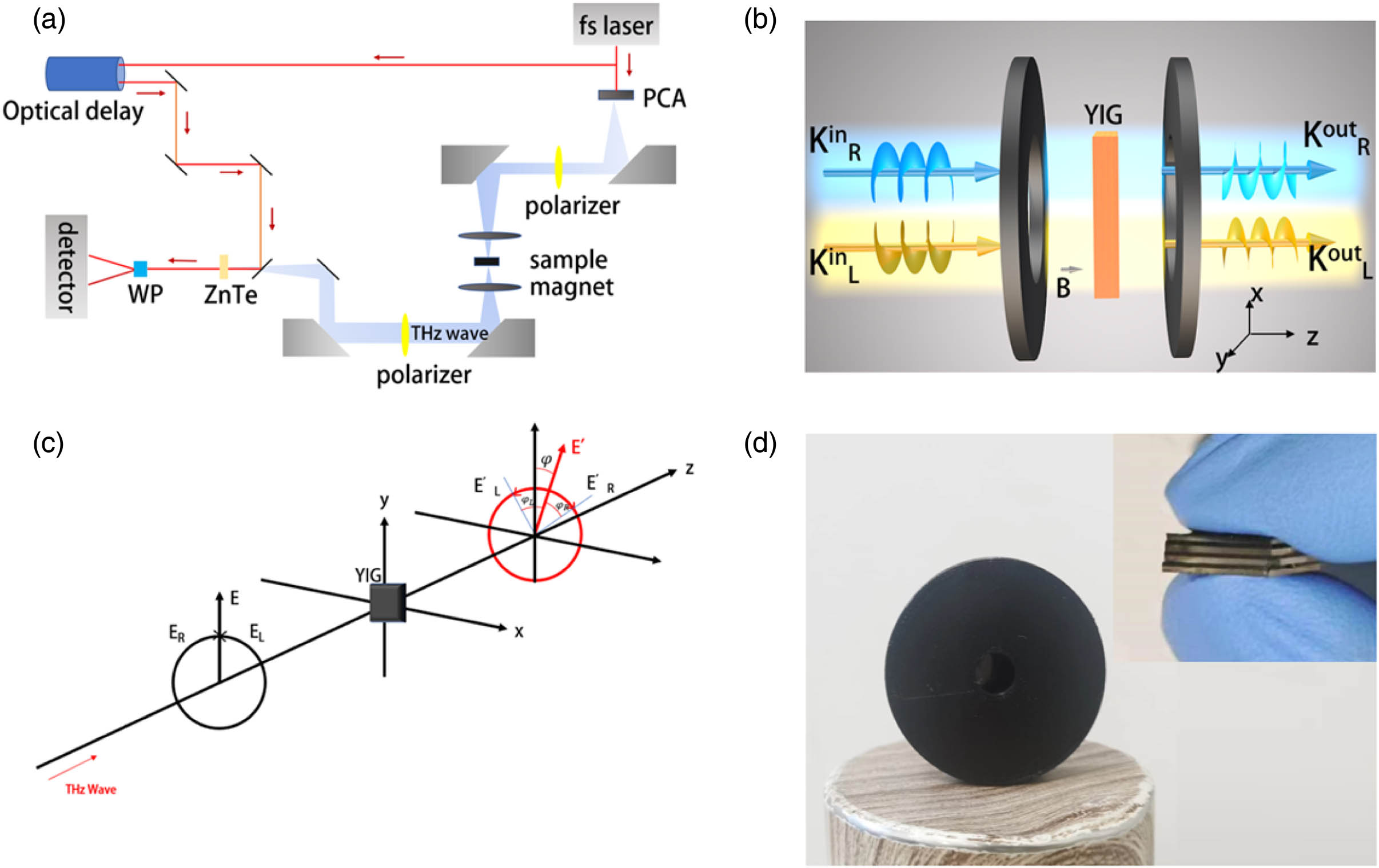
Fig. 1. Schematic diagram. (a) Polarized THz-TDS system with an adjustable magnetic field. (b) THz wave transfer through the sample. (c) Magnetic Faraday rotation effect. (d) Device formed after packaging a sample.
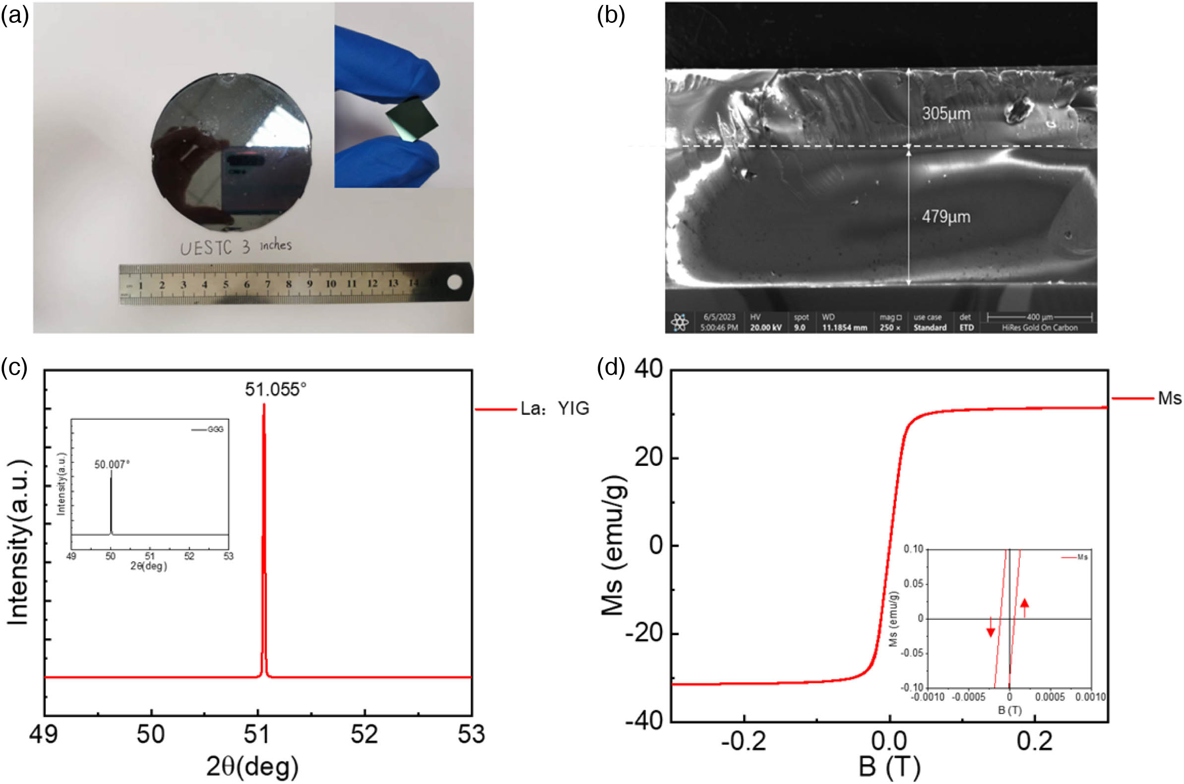
Fig. 2. (a) Photograph of La:YIG sample. (b) SEM image. (c) XRD pattern of La:YIG and GGG film. (d) Hysteresis curve of a La:YIG sample.
Fig. 3. (a) Time domain THz pulses of air and La:YIG film on GGG substrate. (b) Effective refractive index of La:YIG. (c) Transmission and absorption coefficient of one sample under different EMFs. (d) Transmission and absorption coefficient of different numbers of samples (stacked together).
Fig. 4. (a), (b) Phase change of left-handed rotation and right-handed rotation of one La:YIG sample at different EMFs. (c) Faraday rotation angle spectra of one La:YIG sample under the EMF range from − 0.22
Fig. 5. (a), (b) Phase change of left-handed rotation and right-handed rotation of different numbers of YIG samples (stacked together) under ± 0.22 T ± 0.22 T ± 0.22 T
Fig. 6. (a) ± 45 ° LP ± 0.22 T − 45 ° ± 0.22 T + 45 ° ± 0.22 T
Fig. 7. (a), (b) Transmission of eight La:YIG samples (stacked together) with ± 45 ° − 0.26 ± 0.26 T
|
Table 1. Optimized Growth Parameters for La:YIG Films
|
Table 2. Y, La, Fe, O Mole Fractions Obtained by EPMA from the Surface of La:YIG Sample (in %)


Set citation alerts for the article
Please enter your email address

© Copyright 2018-2021 | Chinese Laser Press. All Rights Reserved 沪ICP备15018463号-20