1School of Electronic Science and Engineering, State Key Laboratory of Electronic Thin Film and Integrated Devices, University of Electronic Science and Technology of China, Chengdu 610054, China
2Tianjin Key Laboratory of Optoelectronic Sensor and Sensing Network Technology, Institute of Modern Optics, Nankai University, Tianjin 300350, China
3Shenzhen Institute for Advanced Study, University of Electronic Science and Technology of China, Shenzhen 518110, China
【AIGC One Sentence Reading】:YIG single crystal films, freed from substrate, offer low insertion loss and high Faraday rotation, paving the way for advanced terahertz non-reciprocal devices with enhanced performance.
【AIGC Short Abstract】:Yttrium iron garnet (YIG) holds promise for terahertz applications. This study introduced wafer-level, substrate-free La:YIG single crystal films, exhibiting low insertion loss and absorption coefficient below 1.6 THz. By stacking multiple films, remarkable Faraday rotation angles and isolation were achieved, paving the way for advanced non-reciprocal terahertz devices like isolators and phase shifters.
Note: This section is automatically generated by AI . The website and platform operators shall not be liable for any commercial or legal consequences arising from your use of AI generated content on this website. Please be aware of this.
Abstract
Yttrium iron garnet (YIG) is a promising material for various terahertz applications due to its special optical properties. At present, a high-quality YIG wafer is the desire of terahertz communities and it is still challenging to prepare substrate-free YIG single crystal films. In this work, we prepared wafer-level substrate-free La:YIG single crystal films, for the first time, to our knowledge. Terahertz optical and magneto-optical properties of La:YIG films were characterized by terahertz time domain spectroscopy (THz-TDS). Results show that the as-prepared La:YIG film has an insertion loss of less than 3 dB and a low absorption coefficient of less than below 1.6 THz. Benefitting from the thickness of the substrate-free YIG films and low insertion loss, their terahertz properties could be further manipulated by simply using a wafer-stacking technique. When four La:YIG films were stacked, there was an insertion loss of less than 10 dB in the range of . The Faraday rotation angle of the four-layer-stacked La:YIG films reached 19°, and the isolation could reach 17 dB. By further increasing the stacking number to eight pieces, a remarkable Faraday rotation angle of 45° was achieved with an isolation of 23 dB, which is important for practical application in the THz band. This material may provide a milestone opportunity to make various non-reciprocal devices, such as isolators and phase shifters.
1. INTRODUCTION
A terahertz (THz) wave has broad prospects in biomedical, military, information, and communication fields [1–3], and it has become a research hotspot in recent years under the condition of the gradual growth of high-frequency communication demand [4]. However, there are not many natural substances with a strong electromagnetic response to THz waves [5], and existing microwave devices and infrared or optical devices cannot be directly applied to the THz band, so the study of new key electromagnetic transmission devices suitable for the THz band is a major research hotspot in recent years [6]. Among them, the optical isolator, as an important non-reciprocal optical device, can prevent the reverse transmission of light in the optical path caused by various reasons from adversely affecting the light source and optical path system [7,8]. It mainly uses the Faraday effect of magneto-optical (MO) materials, whose properties are determined by their Faraday rotation angle. Up to now, predecessors have tried to use magnetite [9,10], magnetic fluids [11,12], graphene [13,14], and carbon nanotubes [15] as MO materials. But existing materials have large absorption of THz waves, resulting in excessive insertion loss, weak MO effect, low isolation, or the need for an ultra-low temperature, strong external magnetic field.
Yttrium iron garnet (YIG) is the most widely studied and used of the iron-bearing garnets. As a single crystal, it has relatively small absorption, low loss, high transmittance [16], good non-reciprocal characteristics, low requirements for the working environment, and no need for a strong external magnetic field; room temperature can have a strong magneto-optical response, the optical design is simple, and ferromagnetism is easy to be regulated by external fields. With the maturity of preparation technology, YIG thin films are more and more widely used in microwave and MO devices [17], especially the application of isolators and circulators. Liquid phase epitaxy (LPE) is currently an important method for growing garnet films [18]. However, it is difficult to grow pure YIG film on a gadolinium gallium garnet (GGG) substrate because the lattice matching of pure YIG film and the GGG substrate is poor [19,20], and cracking occurs when the film grows thick. Therefore, it is necessary to change the lattice constant by atomic substitution to reduce the lattice mismatch. In the early stage, we explored the use of lanthanum instead of yttrium iron garnet (La:YIG) as a magneto-optical material, and a film with a thickness of 105 μm can achieve a Faraday rotation of 15° under a magnetic field of 0.155 T [21]. The La:YIG thin films were epitaxially grown on GGG substrates. However, the thickness of the film is not sufficient to polish the GGG substrate, making it impossible to achieve a self-supporting film. GGG itself has losses [22], and the GGG will cause uneven distribution of magnetic fields inside it, which is not conducive to increasing thickness through stacking. In addition, the Faraday rotation angle of 15° is clearly not sufficient for THz isolators in practical applications. In summary, achieving a higher Faraday rotation of 45° requires further increases in film thickness. This can be achieved in two ways: on the one hand, optimizing the growth process by controlling the growth time to appropriately change the thickness of the film, and on the other hand, increasing the thickness through the wafer-stacking approach. Moreover, the MO properties of the material can also be changed by controlling the applied magnetic field (EMF) [23].
Based on the above questions, this paper breaks through the thickness limitation and successfully prepares substrate-free wafer-level La:YIG single crystal films with a size of 3 inches. It is also the first time that substrate-free wafer-level La:YIG single crystal films have been obtained. The high transmittance and low-absorption coefficient of the stacked MO films were measured in the THz band. The THz Faraday rotation effect after La:YIG stacking was studied by using a terahertz time domain spectroscopy (THz-TDS) system and orthogonal polarization detection technology, and the effects of stack thickness and magnetic field changes on sample loss, Faraday rotation angle, and isolation were discussed. The results show that under the premise of maintaining low loss, the required Faraday rotation angle and isolation can be achieved in the THz band through the stacking technology of La:YIG, and the indicators required for practical application can be achieved.
Sign up for Photonics Research TOC. Get the latest issue of Photonics Research delivered right to you!Sign up now
2. METHODS
The nominal composition of lanthanum-doped single crystal YIG film is . Lanthanum-doped single crystal YIG films were prepared on a 3-inch (111) oriented GGG substrate by the standard LPE method. The relationship between the lattice constant of the thin film and the La-doped content can be expressed as follows [24]: where a is the lattice constant of the thin film. When , the value of a is calculated to be 12.378, which is close to the lattice constant of the GGG substrate. For optimal quality, the growth parameters of the film are carefully optimized, as shown in Table 1. Using these growth parameters, 3-inch La:YIG single crystal films were successfully prepared. The wafer was polished to remove the substrate and obtain a thick YIG film with a rough surface, followed by chemical mechanical polishing (CMP) and flattening on a CMP pad sprayed on a rotating CMP for 30 min to finally obtain a substrate-free film. The substrate-free wafer was cut into 10 mm square samples for testing. The thickness of the sample was estimated with scanning electron microscopy (SEM). The internal phase of the sample was detected with high-resolution X-ray diffraction (XRD). The elemental composition of the sample was determined by an electron probe microanalyzer (EPMA). The hysteresis loop of the sample was obtained with a vibrating sample magnetometer (VSM).
Optimized Growth Parameters for La:YIG Films
Flux Composition
Temperature (°C)
Growth Rate (μ)
Rotation Rate ()
Growth Time (min)
Thickness (μm)
0.6
60
508
305
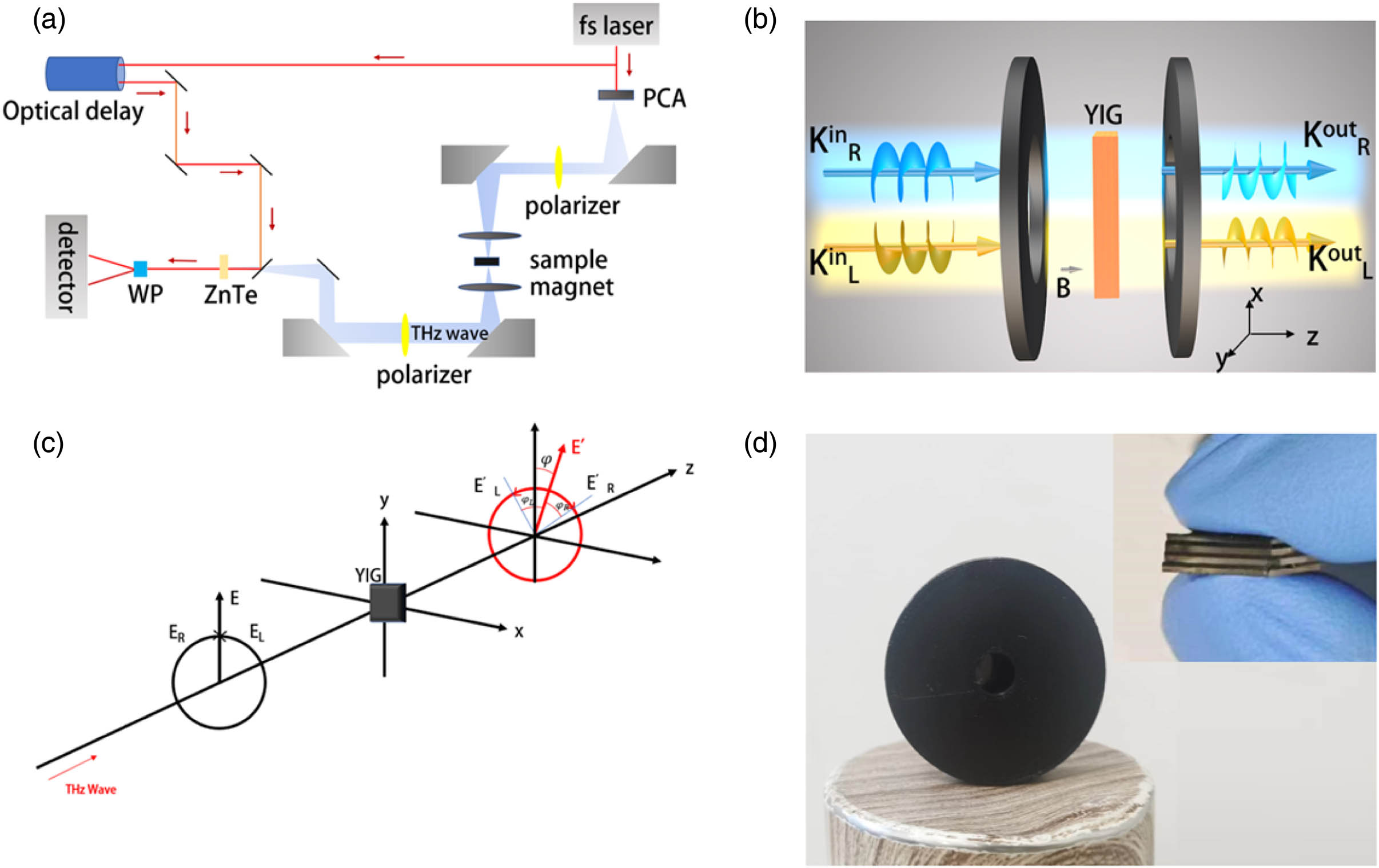
The optical and MO properties of the La:YIG film in the THz band were measured with the THz-TDS system, as shown in Fig. 1(a). A mode-locked titanium sapphire laser is used to generate a femtosecond laser beam with a duration of 75 fs, a repetition rate of 80 MHz, and a wavelength of 800 nm. The laser generated by the laser is divided into a pump beam that generates a THz pulse and a detection beam that detects a THz signal through a beam splitter. A GaAs photoconductive antenna (PCA) was used to generate THz pulses. A ZnTe crystal was used to detect terahertz signals. A set of ring magnets is used to apply a magnetic field to the sample. The magnetic field can be adjusted between and . Change the magnetic field magnitude by changing the number of magnets. Positive and negative represent the opposite directions of the magnetic field. The maximum magnetic field required for this experiment was 0.26 T, which requires six pairs of ring magnets. As shown in Fig. 1(b), the sample is placed as a Faraday configuration in the middle of the ring magnets on both sides; the direction of the magnetic field and the direction of the THz wave are strictly along the direction. Two THz wire-grid polarizers (WGPs) are placed relatively parallel to each side of the magnet. The first WGP is used to ensure that all incident waves are incident with linearly polarized light. The second WGP can be rotated to measure the synthesis of circularly polarized light by longitudinally magnetizing the linear polarization component of the YIG sample at and . The humidity of the experimental environment was about 10%, and it was performed at room temperature.
Figure 1.Schematic diagram. (a) Polarized THz-TDS system with an adjustable magnetic field. (b) THz wave transfer through the sample. (c) Magnetic Faraday rotation effect. (d) Device formed after packaging a sample.
Using orthogonal polarization detection, the Faraday rotation angle of a thin film can be measured. This is shown in Fig. 1(c). Polarized light in the incident direction (black curve, ) can be decomposed into left-handed (EL) and right-handed (ER) circular polarization. The time domain signal in the polarization direction is obtained by THz-TDS, and the amplitude () and phase () can be simulated by the Fourier transform. The elliptic polarization of the emitted light is expressed as
The complex amplitudes of the and states can be expressed as follows:
And, based on the complex amplitude, the phase shift of the and states can be calculated as and . Then the Faraday rotation angle can be expressed as [25]
In addition, we also calculate the refractive index, and transmission and absorption rates of La:YIG crystals separately, and the formulas are as follows: where and represent the intensity of incident and outgoing light. is the angular frequency, is the phase difference between the sample and the reference, and is the thickness of the crystal.
To facilitate measurement, we designed a housing that can package the sample and place the sample in it to form a simple optical rotation device, as shown in Fig. 1(d).
3. RESULTS AND DISCUSSION
Figure 2.(a) Photograph of La:YIG sample. (b) SEM image. (c) XRD pattern of La:YIG and GGG film. (d) Hysteresis curve of a La:YIG sample.
Figure 2(c) is the XRD pattern of the sample. From the image, it can be seen that the diffraction peak of La:YIG is located at 51.055°, while the diffraction peak of the GGG substrate is located at 50.007° [21]. The positions of the two are relatively close, indicating that the lattice matching is better. It is important to reduce the loss of THz waves caused by crystal defects. Figure 2(d) is a normalized VSM curve for the sample with a saturated magnetic field of approximately 0.22 T, which can be used as a reference value for EMF. From the above results, it can be concluded that the La:YIG film prepared this time has a pure single crystal garnet phase and has a good lattice match with the single crystal GGG substrate.
The THz-TDS system was first used to measure the THz time domain pulse signal of one sample, as shown in Fig. 3(a). Subsequently, the frequency domain spectrum was obtained by the Fourier transform, and read the light intensity, phase, and other information. The refractive index is calculated by Eq. (7), as shown in Fig. 3(b), where the refractive index of the La:YIG sample is approximately 4.01 in the range of 0.1–1.6 THz. Then, using Eqs. (8) and (9) and changing the magnetic field, the transmittance and absorption coefficients of the La:YIG sample in different magnetic fields were calculated, as shown in Fig. 3(c). When the frequency is in the 0.1–1.6 THz range, the insertion loss is less than . The absorption coefficient of La:YIG is always less than when the frequency is less than 1 THz, and even if the frequency reaches 1.6 THz, the absorption coefficient is still less than . The low loss of this sample provides the possibility for sample stacking to increase thickness. Figure 3(d) is the comparison of the transmission and absorption coefficients of samples with one, two, three, and four stacks. The result shows that the absorption coefficient is independent of the number of stacked pieces. Even if the four films are stacked, the absorption coefficient is still less than . This is due to the fact that the four samples are from materials grown on the same wafer, have uniform properties, and have similar refractive indices, so the THz wave loss between sheets is almost negligible. It further demonstrates the feasibility of the method of increasing the thickness by stacking. At the same time, as the number of stacked pieces increases, the transmission of the sample decreases, and the insertion loss increases, reaching a maximum of . This is because the absorption coefficient is a parameter with the thickness of the material as the denominator, and as the thickness increases, the overall absorption of the material increases, resulting in the increase in insertion loss and decrease in transmission. But this trend is not obvious at low frequencies. The insertion loss is less than in the range of 0.1–1.2 THz, and the resulting losses are acceptable. At the same time, the real part of the dielectric constant of the sample is as high as 16.1, indicating that it has the characteristics of high dielectric function and low dispersion. It is fit for the preparation of THz integrated waveguide devices.
Figure 3.(a) Time domain THz pulses of air and La:YIG film on GGG substrate. (b) Effective refractive index of La:YIG. (c) Transmission and absorption coefficient of one sample under different EMFs. (d) Transmission and absorption coefficient of different numbers of samples (stacked together).
Then, in order to elucidate the effect of the magnetic field on the phase shift of the left and right circularly polarized light, we calculated the phase shift of the left and right circular polarized light caused by a YIG sample at and , which can be calculated by
As shown in Figs. 4(a) and 4(b), it can be seen that with the increase of the forward magnetic field, the phase shift of left-handed circularly polarized light increases in the forward direction, and when the magnetic field increases in the opposite direction, the phase shift of left-handed optical light increases in the opposite direction. The right-handed optical phase shift changes the opposite trend with the magnetic field. When the magnetic field changes from to , the phase shift of left-handed and right-handed polarized light can reach the maximum of 4.3° and 6.4°. It is because under the same magnetic field, the phase shift directions of the left and right rotational polarized light are exactly the opposite, resulting in the magnetic Faraday optical rotation effect. Then, using Eq. (6), we calculate the trend of Faraday’s rotation angle with the increase of the magnetic field, as shown in Fig. 4(c). When the magnetic field increases to 0.22 T, Faraday’s rotation angle can reach the maximum of 4.9°. We usually use the Verdet constant to describe the optical rotation of a medium per unit thickness under the action of a unit magnetic field, which can be calculated by where is Faraday’s rotation angle, is the sample thickness, and is the EMF strength. The Faraday rotation spectrum at a magnetic field of 0.22 T was chosen for calculation. As is shown in Fig. 4(d), the Verdet constant of the calculated YIG crystal can reach 74 deg/(mm T). It shows that the sample has good optical rotation performance.
Figure 4.(a), (b) Phase change of left-handed rotation and right-handed rotation of one La:YIG sample at different EMFs. (c) Faraday rotation angle spectra of one La:YIG sample under the EMF range from to 0.22 T. (d) Verdet constant spectrum of La:YIG calculated from the polarization rotation angle at an EMF of 0.22 T.
In addition, we measured the phase shift of the left and right circular polarization as the number of YIG sample pieces increased, and the results are shown in Figs. 5(a) and 5(b). It can be seen that with the increase of the number of pieces, the phase shift of the left and right circular polarization gradually increases, and the phase shift increases by each piece are roughly the same. Therefore, we can increase the phase shift of the left and right rotational polarization by increasing the sample thickness, thereby obtaining a larger Faraday rotation angle. According to Eq. (6), we calculated the Faraday rotation angle for different numbers of sample stacks, and the results are shown in Fig. 5(c). The trend of Faraday rotation angle with the increase of the number of samples was summarized, as shown in Fig. 5(d). It can be seen that with the increase of the number of samples, the Faraday rotation angle gradually increases, and the maximum can reach 19°. To visualize the MO effect of the sample as a function of stack thickness, we plotted the polarization state of a stack of one to four samples at 0.6 THz under a 0.22 T magnetic field, as shown in Figs. 5(e) and 5(f). Moreover, the increases in Faraday rotation angle for each sample are almost the same, and the Faraday rotation angle increases exponentially with the increase in the number of pieces (i.e., the increase in thickness). This also opens the possibility to increase the Faraday rotation angle by further increasing the thickness of the stack.
Figure 5.(a), (b) Phase change of left-handed rotation and right-handed rotation of different numbers of YIG samples (stacked together) under . (c) Faraday rotation angle spectra of different numbers of YIG samples (stacked together) under . (d) Faraday rotation angle changes with the number of sample stacks. (e), (f) Polarization states of the transmitted THz wave through one to four stacked La:YIG films at 0.6 THz under .
After that, the transmission isolation of the four YIG samples (stacked together) was calculated by measuring the transmittance at at or at a fixed exit polarizer angle. Figure 6(a) is the measured time domain pulse signal, and the transmittance is obtained by using the previous method after the Fourier transform, as shown in Figs. 6(b) and 6(c). Subsequently, the difference between the transmittance of the forward and reverse magnetic fields is calculated to obtain the isolation, as shown in Fig. 6(d). The image shows that when the Faraday rotation angle is maximum, 17 dB of isolation can be obtained.
Figure 6.(a) time domain THz pulses of four stacked La:YIG films under the EMF of . (b) transmission under the EMF of . (c) transmission under the EMF of . (d) Isolation of four stacked La:YIG films under the EMF of 0.22 T.
The above experiments show that it is feasible to increase the overall thickness by stacking multiple pieces of La:YIG on top of each other, thereby improving the Faraday rotation angle and isolation. Therefore, we did a test of eight more stacked samples. The forward and reverse magnetic field transmittances were first tested, as shown in Figs. 7(a) and 7(b). It can be seen that the transmittance of exit polarized light increases with the increase of the forward magnetic field and decreases with the increase of the reverse magnetic field, and the transmittance of exit polarized light changes with the magnetic field is exactly the opposite. When the EMF reaches the insertion loss of 45° outgoing polarized light is kept below . We measured the Faraday rotation angle and isolation of eight sample stacks under different magnetic fields, as shown in Figs. 7(c) and 7(d). To visualize the MO effect of the sample as a function of stack thickness, we plotted the polarization state of eight sample stacks from 0 to magnetic field at 0.6 THz, as shown in Figs. 7(e) and 7(f). We also plotted the Faraday rotation angle and isolation as a function of EMF, as shown in Figs. 7(g) and 7(h). When the EMF reaches 0.26 T, the Faraday rotation angle of the eight-piece sample stack can reach 45°, and the isolation can reach a maximum of 23 dB. When the Faraday rotation angle reaches about 45°, it can already be used in the production of isolators [26–28]. As a result, we can achieve high Faraday rotation and isolation by increasing the stack thickness of the sample while maintaining the highest possible transmission and lowest possible losses, thus meeting commercial requirements.
Figure 7.(a), (b) Transmission of eight La:YIG samples (stacked together) with linearly polarized light. (c) Faraday rotation angle spectra of eight La:YIG samples (stacked together) under the EMF range from to 0.26 T. (d) Isolation of eight stacked La:YIG films under the EMF range from 0 to 0.26 T. (e), (f) Polarization states of the transmitted THz wave through eight stacked La:YIG films at 0.6 THz from 0 to . (g) Faraday rotation angle spectrum of eight La:YIG samples changes with magnetic field. (h) Isolation of eight stacked La:YIG films changes with magnetic field.
In summary, we have successfully prepared substrate-free La:YIG films by using an improved liquid phase epitaxy method, and packaging them into a simple polarimetric device. The as-prepared substrate-free La:YIG films have single crystal structure with a thickness as large as 305 μm. Thanks to the thickness of the substrate-free YIG films and low insertion loss, we could simply use a wafer-stacking technique to further manipulate their terahertz properties. The results show that in the range of 0.1–1.2 THz, the four-piece stacked La:YIG has an insertion loss of less than and a low absorption coefficient of less than . In addition, the Faraday rotation effect of the sample was tested by the orthogonal polarization method, the Faraday rotation angle of a single sample can reach 4.9°, and the Verdet constant is about 74 deg/(mm T). When four samples are stacked on top of each other, Faraday rotation can reach 19° and isolation can reach 15 dB. Subsequently, the number of stacked pieces was increased to eight under the condition that the transmittance was not significantly reduced at low frequencies, and finally a rotation angle of 45° and an isolation degree of 23 dB were obtained, which was suitable for practical isolator production. Therefore, the film has the potential to be widely used in commercial THz wave isolators by using the wafer-stacking approach.
[25] D. Zhao, F. Fan, Q. Y. Wen. Terahertz phase shift of circularly polarized wave and faraday rotation in magnetized YIG crystal. IEEE MTT-S International Microwave Workshop Series on Advanced Materials and Processes for RF and THz Applications (IMWS-AMP), 1-3(2022).
 AI Video Guide
  AI Picture Guide
 AI One Sentence