• Journal of Semiconductors
  • Vol. 41, Issue 10, 102403 (2020)
Zhang Zhang, Chao Chen, Tairan Fei, Hao Xiao, Guangjun Xie, and Xin Cheng
Author Affiliations
  • School of Electronics Science and Applied Physics, Hefei University of Technology, Hefei 230009, China
  • show less
    DOI: 10.1088/1674-4926/41/10/102403 Cite this Article
    Zhang Zhang, Chao Chen, Tairan Fei, Hao Xiao, Guangjun Xie, Xin Cheng. Wireless communication and wireless power transfer system for implantable medical device[J]. Journal of Semiconductors, 2020, 41(10): 102403 Copy Citation Text show less
    Schematic diagram of the system.
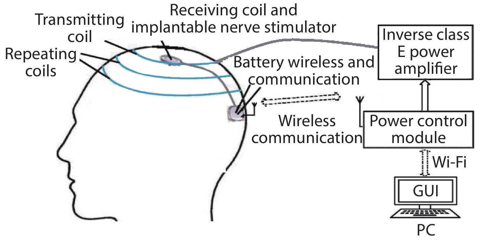
    Fig. 1. Schematic diagram of the system.
    The block diagram of the WC-WPT system.
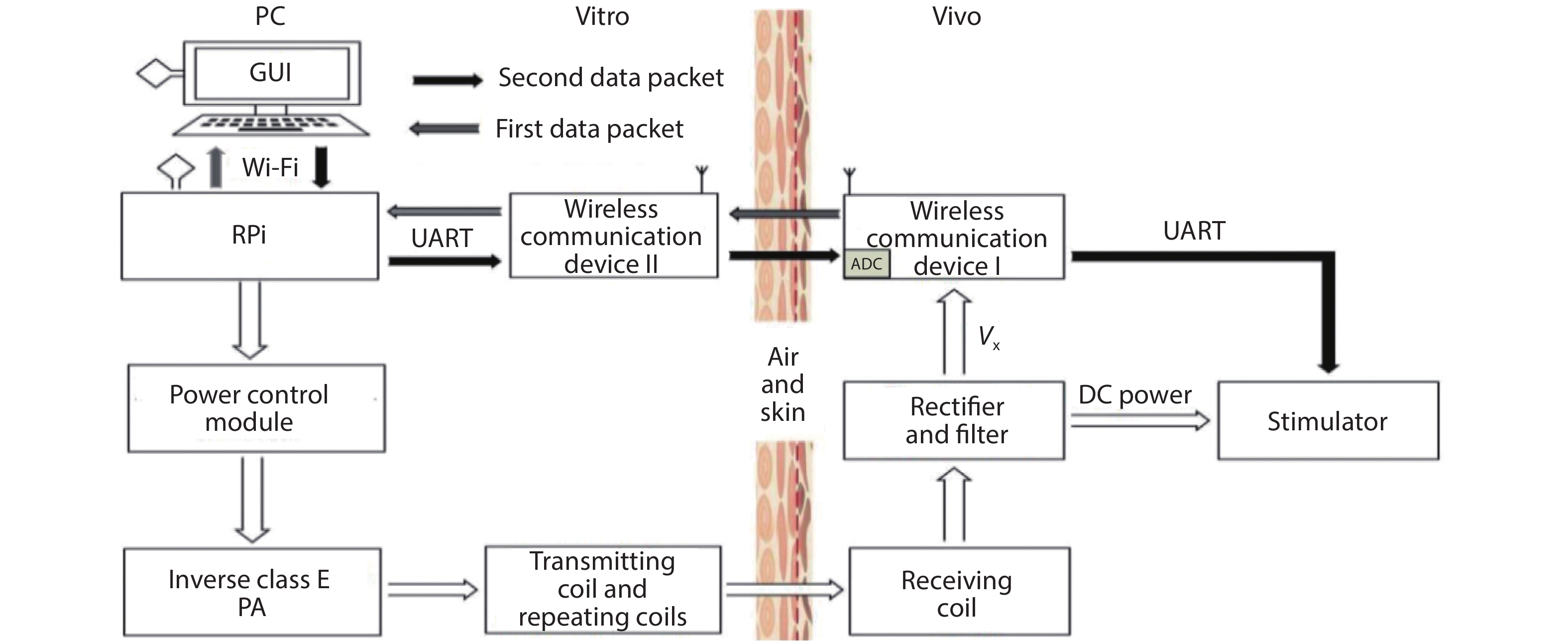
    Fig. 2. The block diagram of the WC-WPT system.
    Inverse class E PA.
    Fig. 3. Inverse class E PA.
    The structure of transmitting coil and repeating coils.
    Fig. 4. The structure of transmitting coil and repeating coils.
    The PSSP type four-coil resonant topology.
    Fig. 5. The PSSP type four-coil resonant topology.
    (Color online) The relationship between efficiency and coupling coefficient: (a) k12, (b) k23 and (c) k34.
    Fig. 6. (Color online) The relationship between efficiency and coupling coefficient: (a) k12, (b) k23 and (c) k34.
    The specific adjustment process.
    Fig. 7. The specific adjustment process.
    (Color online) The GUI for control of stimulator parameters.
    Fig. 8. (Color online) The GUI for control of stimulator parameters.
    (Color online) The experimental system.
    Fig. 9. (Color online) The experimental system.
    (Color online) Performance of PTE: (a) two-coil Structure, and (b) four-coil structure.
    Fig. 10. (Color online) Performance of PTE: (a) two-coil Structure, and (b) four-coil structure.
    (Color online) Variation of receiving voltage at (a) open-loop system and (b) closed-loop system.
    Fig. 11. (Color online) Variation of receiving voltage at (a) open-loop system and (b) closed-loop system.
    ComponentLLfCxRx
    Computing formula
    Table 1. The calculation formula of main components of the inverter circuit.
    Coil numberDiameter (cm)Inductance (μH) Parasitic resistance (Ω)Compensation capacitance (nF)
    Coil 16. 012. 030. 222. 11
    Coil 28. 118. 580. 261. 36
    Coil 310. 022. 620. 271. 12
    Table 2. The parameters of the coils and resonant compensation capacitance at 1 MHz.
    Publication2013[13]2016[6]2016[14]2018[7]This work
    Power carrier frequency (MHz)13.813.5613.56100.11
    Coil configuration23244
    Closed-loop controlYesYesNoNoYes
    Real-time controlNoNoYesNoYes
    Wireless communicationLSKLSK//nRF24L01
    PTE/13.5% @ 20 mm10% @ 20 mm12.5% @ 400 mm18.5% @ 20 mm
    Tx coil diameter (mm)/282080120
    Rx coil diameter (mm)/34108021
    Potential applicationIMDsIMDsIMDs/IMDs
    Table 3. Benchmarking of WPT system.
    Zhang Zhang, Chao Chen, Tairan Fei, Hao Xiao, Guangjun Xie, Xin Cheng. Wireless communication and wireless power transfer system for implantable medical device[J]. Journal of Semiconductors, 2020, 41(10): 102403
    Download Citation