
Zhang Zhang, Chao Chen, Tairan Fei, Hao Xiao, Guangjun Xie, Xin Cheng. Wireless communication and wireless power transfer system for implantable medical device[J]. Journal of Semiconductors, 2020, 41(10): 102403
- Journal of Semiconductors
- Vol. 41, Issue 10, 102403 (2020)
Abstract
1. Introduction
With the development of medical electronic device, implantable medical devices (IMDs) are widely used in the clinic[
In clinical application, it is necessary to provide long-term and stable power for IMDs, and the use of a disposable battery is limited by its capacity and service life. Regular surgery is required to replace the battery, which will bring great suffering and even life danger to patients. Massachusetts Institute of Technology (MIT) professor Marin Soljacic proposed the magnetically-coupled resonant wireless power transfer (MCR-WPT) in 2007[
In IMDs, the relative position between receiving coil and the transmitting coil will change as the patient moves, as will the receiving voltage. Therefore, a closed-loop power control system needs to be established to stabilize the receiving voltage. Ref. [5] stabilizes the Rx voltage by introducing a dynamic LC resonant network to dynamically compensate for the variation of the Rx resonant capacitance caused by external changes. However, this method does not solve the problem of power loss caused by the detuning of the Tx. Ref. [6] adopts load shift keying (LSK) communication mode, using radio frequency identification (RFID) chip to demodulate LSK data and adding control circuit to adjust transfer power at the Tx to stabilize the receiving voltage. However, the LSK modulation mode transmits data by modulating the power carrier and through the coil coupling. When the coupling degree between coils is weak or changes dynamically, the LSK mode is obviously unreliable. In addition, the LSK mode requires a long off-time when transmitting large amounts of data, which will affect the normal power supply for the IMDs. Ref. [7] proposes strongly coupled magnetic resonance WPT systems with high quality factor, and which improves the coupling between the Tx/Rx coil and their corresponding resonators. Compared to a conventional system, the bandwidth is increased by over 100% without sacrificing much of the efficiency. Ref. [8] proposes a single-loop WPT system with an adjustable compensation network in which the capacitor array can be altered. When the coils' distance ranges from 32 to 40 mm and the load resistance varies from 100 to 500 Ω, the capacitor array can be adjusted automatically to offer the load almost constant voltage at 3.4 V. However, these studies have only realized wireless power transfer, and wireless communication functions are also needed in IMDs.
Similar to drug therapy, the stimulus parameters of implanted nerve stimulus also need to be artificially controlled. According to the clinical response and the treatment needs of different patients, the doctor should customize the treatment plan, and then adjust the stimulus parameters of the implanted nerve stimulator to treat the disease[
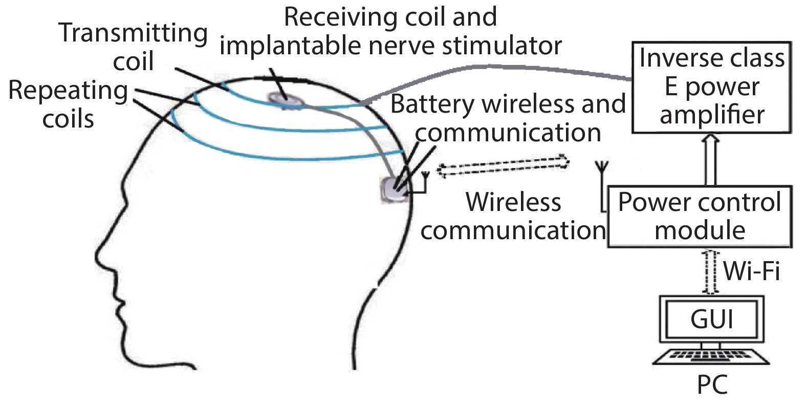
This paper proposes a wireless communication wireless power transfer (WC-WPT) system that has a wearable four-coil structure to enhance the magnetic coupling of the coils to improve the efficiency of wireless power transfer and a closed-loop control structure to stabilize the voltage caused by coil displacement variations, using for implantable nerve stimulators, as shown in Fig. 1. This system adopts MCR-WPT mode, operating at 1 MHz. To avoid the disadvantage of using the modulation power carrier to transmit the data, the 2.4 GHz monolithic high-speed wireless transceiver chip nRF24L01 is used to realize the two-way transfer of voltage data and stimulus parameters between the implanted device and the outside. To keep the receiving voltage constant and provide stable DC power for the IMDs when the external factors change, the power regulation module controlled by Raspberry Pi (RPi) is designed for the system. In addition, on the personal computer (PC) terminal, a graphical user interface (GUI) was designed and connected with RPi through Wi-Fi. RPi, not only to complete the simple I/O control pin but also to run the corresponding operating system and complete more complex task management and scheduling to support the development of higher-level applications. This enables the user to monitor the power supply status and the configure stimulus parameters on a PC. In Section 2, the key modules of WC-WPT system are introduced. The test results and analysis of the system are presented in Section 3, followed by our conclusions in Section 4.
![]()
Figure 1.Schematic diagram of the system.
2. Proposed method
Fig. 2 shows a simplified block diagram of the proposed WC-WPT system, which is based on the MCR-WPT technology. In this system, the RPi is used as the central controller of the system and a wireless communication module (nRF24L01) is adopted to transmit data between the Tx and the Rx. The power control module in Tx adjusts the supply voltage of power amplifier (PA) to compensate for any coupling/loading variations. The GUI on the PC is designed to allow the users to easily monitor and control the IMDs, and connect to RPi through Wi-Fi.
![]()
Figure 2.The block diagram of the WC-WPT system.
2.1. Inverse class E PA
The inverse class E PA, shown in Fig. 3, is a new type of structure PA improved by Mury and Fusco in 2005 on the basis of class E PA[
![]()
Figure 3.Inverse class E PA.
2.2. PSSP type four-coil resonant network
When the transfer distance (d) is greater than the average radius (rm) of the transmitting coil and the receiving coil, the power transfer efficiency (PTE) of the two-coil system will be less than 40 percent because of the low quality factor and low coupling. When d is far greater than rm, the efficiency decreases exponentially with d. The receiving coil using in IMDs is often required very small size. If the traditional two-coil resonant network structure is used in the system, then the PTE of the system will be very low. Moreover, the two-coil structure requires the planes of transmitting coil and the receiving coil keep parallel as far as possible during the process of WPT, otherwise, the PTE will be reduced. These bring many limitations to the clinical application of wireless power supply systems. Because the signal frequency of the system is 1 MHz, the use of parallel compensation capacitance in the transmitting coil and receiving coil can effectively improve the power factor, reduce losses, and the input impedance does not significantly change the load. The use of series compensation capacitance in the repeating coils does not have to consider load changes, and the voltage regulation effect is more obvious. Consequently, the parallel-series-series-parallel (PSSP) type four-coil resonant topology is adopted in this design. By adding two repeating coils to enhance the coupling between the coils and improve the PTE, the structure is shown in Fig. 4. The parameters of the coils and the resonant compensation capacitance at 1 MHz are shown in Table 2, the number of turns for all coils is six.
![]()
Figure 4.The structure of transmitting coil and repeating coils.
The PSSP type four-coil resonant topology is shown in Fig. 5. The R1, R4 are the equivalent series resistance of the transmitting end and the receiving end, respectively, and the R2, R3 are the equivalent series resistances of the inductance coils L2 and L3, respectively. Mxy represents the mutual inductance of the coil Lx and the coil Ly. The value of the resonant compensation capacitance needs to meet:
![]()
Figure 5.The PSSP type four-coil resonant topology.
where ω is the angular velocity of the wireless power supply system.
Based on the principle of mutual inductance, the coupling coefficient (Kxy) between Lx and Ly can be expressed as follows:
where (x,y) ∈{(1,2), (2,3), (3,4)}.
When the system is resonant, the quality factor Qn of each coil can be expressed as:
where n ∈{1,2,3,4}, we can get the PTE (η) formula as:
From Eq. (4), low coupling between the repeating coils can be compensated by a high-Q factor of these coils. It can be inferred that for a given coupling between the repeating coils, as the Q factor of the coils increases, the power transmission efficiency increases. To achieve high power transmission efficiency for a high operating range, high Q-factor repeating coils are required[
![]()
Figure 6.(Color online) The relationship between efficiency and coupling coefficient: (a)
The efficiency of a two-coil power transfer system is given by Ref. [12]:
It can be seen that the four-coil model is similar to the two-coil system model. Because in the four-coil system, Q2 and Q3 are independent of the source resistance and load resistance, higher quality factors of the repeating coils can be achieved than two-coil system.
Assuming
If the transmitting power Pout is assumed to remain unchanged, the receiving power Prec can be expressed as:
It can be seen from the above analysis that changes in coupling degree of any two coils will result in a change in receiving power, which will affect the normal stable power supply to the IMDs.
2.3. Wireless communication and power control module
In this design, the monolithic high-speed wireless transceiver chip nRF24L01 and STM32 microcontroller are adopted as the wireless communication devices. The current consumption of the nRF24L01 is extremely low and the size is small, making it suitable for wireless communication of implantable devices. The 12-bit high-speed ADC integrated in the STM32 chip collects the receiving voltage data and sends it to the outside of the body through the nRF24L01 wireless communication module.
As show in Fig. 2, the receiving voltage value (Vx) is collected and packaged as the first data packet, and then sent to the RPi through the wireless communication device. The RPi compares Vx with the reference voltage (Vs) set by users and then adjusts the transmitting power by adjusting the PA supply voltage. The specific adjustment process of the system is shown in Fig. 7. When Vs equals Vx, the entire adjustment process ends directly. When Vs is less than Vx, the transmitting power is reduced by reducing the DC supply voltage to achieve Vx reduction. When Vs is greater than Vx, the transmitting power is increased by increasing the DC supply voltage to achieve Vx rise. The voltage adjustment circuit structure is composed of a digital potentiometer (X9C104) and a DC–DC chip (TPS61170). The digital potentiometer can adjust its own resistance according to the control signal of CS, U/P and INC pins output by RPi, and the DC–DC output voltage (supply for the PA) will change with the resistance of digital potentiometer. The wireless communication module mainly realizes the transmission of the stimulus parameters of the PC and the regulated voltage parameters of RPi. The Vx parameters received by RPi are compared with Vs, and the obtained adjustment results are communicated through the microcontrollers. The PC's stimulus parameters are transmitted by the GUI, as described in the next section.
![]()
Figure 7.The specific adjustment process.
2.4. Design of the GUI
The GUI shown in Fig. 8 is realized based on the graphical programming language LabView, with the PC used as the upper computer, and the RPi with Wi-Fi communication function is used as the lower computer. The connection between the upper computer and the lower computer is established through TCP/IP protocol. The user can adjust the stimulus parameters in the Parameter Adjustment Area, and then click the Send Parameter button after the adjustment is completed. The stimulus parameters mainly include electrode selection, stimulus cycle, capacitor number, width of pulse and stimulus voltage. The GUI will convert the stimulus parameters into corresponding binary codes and pack the data of the stimulus parameters adjustment into the second data packet, which will be sent to the RPi through Wi-Fi, and then transmitted to the stimulator in the body through the wireless communication device.
![]()
Figure 8.(Color online) The GUI for control of stimulator parameters.
3. Results and analysis
According to this design, the experimental system shown in Fig. 9 is built to verify the feasibility of the design. The function signal generator is used to generate a 1 MHz square wave signal as the driving signal of the inverse class E PA, and the DC power supply provides DC power to the system. The coils are wound with a 0.5 mm diameter enamelled wire, and the specific parameters of the transmitting and repeating coils are shown in Table 2.
![]()
Figure 9.(Color online) The experimental system.
First, the experiment focuses on the system’s performance in power transfer under open-loop condition. Experiment tests the PTE variation of the four-coil structure with the transfer distance and the deflection angle between the receiving coil and the transmitting coil, in addition to comparison with the two-coil structure. The results are shown in Fig. 10. It can be seen that when the transfer distance is greater than 10 mm and the deflection angle is greater than 10 degrees, the performance of the four-coil structure in terms of PTE and stability are significantly better than that of the two-coil structure.
![]()
Figure 10.(Color online) Performance of PTE: (a) two-coil Structure, and (b) four-coil structure.
When the relative position of the coils mutates, changes of the receiving voltage and the PA supply voltage in open-loop system are shown in Fig. 11(a), and the same condition in closed-loop system with power control module is shown in Fig. 11(b). It can be seen from the Fig. 10 that when the distance of the coil increases, the voltage at the receiving end will decrease. The open-loop system cannot adjust the receiving voltage, but the power control module in the closed-loop system increases the transmitting power in time, and the voltage at the receiving end can quickly recover to the reference voltage. Table 3 compares this work with excellent papers[
![]()
Figure 11.(Color online) Variation of receiving voltage at (a) open-loop system and (b) closed-loop system.
4. Conclusion
Based on the traditional magnetic coupling resonance wireless power transfer technology, a wireless power supply and wireless communication system applied to implanted nerve stimulator is designed in this paper. The wireless communication module and power regulation circuit are added to the system. In addition, based on the traditional two-coil resonant structure, this paper has designed a wearable four-coil PSSP resonant structure, effectively improving the system’s PTE performance when transfer distance and the deflection angle of transmitting coil and receiving coil increase. This work can efficiently realize closed-loop real-time control and complete wireless power transfer and wireless communication between coils. The closed-loop structure adjusts the output voltage in real time to ensure the stability of the voltage value, and the PC terminal controls the stimulus parameters in real time through wireless communication. Wireless communication devices make data transfer more reliable, and four-coil resonant structure can maintain good efficiency even when the transfer distance of the system increases. In all, the system designed in this paper provides an effective solution for wireless power supply and communication problems of IMDs.
Acknowledgements
This work was supported by the National Natural Science Foundation of China (61674049, U19A2053), State Key Lab of ASIC and System (2019KF003) and the Fundamental Research Funds for Central Universities (JZ2019HGTB0092).
References
[1] R F Xue, K W Cheng, M Jie. High-efficiency wireless power transfer for biomedical implants by optimal resonant load transformation. Circuits Syst I, 60, 867(2013).
[2]
[3] C H Liu, C Q Jiang, J G Song et al. An efficiency sandwiched wireless power transfer system for charging implantable cardiac pacemaker. IEEE Trans Ind Electron, 66, 4108(2019).
[4] A Kurs, A Karalis, R Moffatt et al. Wireless power transfer via strongly coupled magnetic resonances. Science, 317, 83(2007).
[5] S O’Driscoll, A S Y Poon. Meng T H. A mm-sized implantable power receiver with adaptive link compensation. IEEE International Solid-State Circuits Conference, 294(2009).
[6] B Lee, M Kiani, M Ghovanloo. A triple-loop inductive power transmission system for biomedical applications. IEEE Trans Biomed Circuits, 10, 138(2016).
[7] W S Zhou, S Sandeep, P D Wu et al. A wideband strongly coupled magnetic resonance wireless power transfer system and its circuit analysis. IEEE Microwave Wireless Compon Lett, 28, 1152(2018).
[8]
[9] L Liu, L He, Y Zhang et al. A battery-less portable ECG monitoring system with wired audio transmission. IEEE Trans Biomed Circuits Syst, 13, 697(2019).
[10] T Mury, V F Fusco. Series-L/parallel-tuned comparison with shunt-C/series-tuned class-E power amplifier. IEE Proc-Circuits, Devices Syst, 152, 709(2005).
[11] A Kumar, S Mirabbasi, M Chiao. Resonance-based wireless power delivery for implantable devices. Proc IEEE Biomedical Circuits and Systems Conf, 25(2009).
[12] L B Qian, J F Sang, Y S Xia et al. Investigating on through glass via based RF passives for 3-D integration. IEEE J Electron Devices Soc, 6, 755(2018).
[13] H Xu, U Bihr, J Becker et al. A multi-channel neural stimulator with resonance compensated inductive receiver and closed-loop smart power management. IEEE International Symposium on Circuits and Systems, 638(2013).
[14] D W Seo, S T Khang, S C Chae et al. Open-loop self-adaptive wireless power transfer system for medical implants. Microwave Opt Technol Lett, 58, 1271(2016).


Set citation alerts for the article
Please enter your email address

© Copyright 2018-2021 | Chinese Laser Press. All Rights Reserved 沪ICP备15018463号-20