• Photonics Research
  • Vol. 5, Issue 5, 396 (2017)
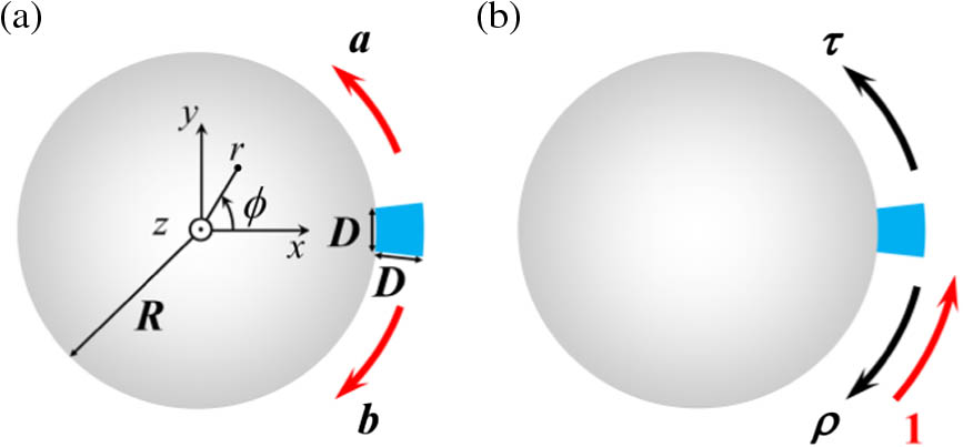
Junda Zhu1, Ying Zhong2, and Haitao Liu1、*
Author Affiliations
  • 1Key Laboratory of Optical Information Science and Technology, Ministry of Education, Institute of Modern Optics, Nankai University, Tianjin 300350, China
  • 2State Key Laboratory of Precision Measuring Technology and Instruments, Tianjin University, Tianjin 300072, China
  • show less
    DOI: 10.1364/PRJ.5.000396 Cite this Article Set citation alerts
    Junda Zhu, Ying Zhong, Haitao Liu. Impact of nanoparticle-induced scattering of an azimuthally propagating mode on the resonance of whispering gallery microcavities[J]. Photonics Research, 2017, 5(5): 396 Copy Citation Text show less
    (a) Schematic of a z-invariant cylindrical microcavity with a nanoparticle (blue sector) adsorbed on its surface. a and b denote the complex amplitude coefficients of the two counterpropagating APMs matched to the resonant mode. (b) Scattering coefficients ρ and τ characterizing the reflection and transmission of the APM at the nanoparticle.
    Fig. 1. (a) Schematic of a z-invariant cylindrical microcavity with a nanoparticle (blue sector) adsorbed on its surface. a and b denote the complex amplitude coefficients of the two counterpropagating APMs matched to the resonant mode. (b) Scattering coefficients ρ and τ characterizing the reflection and transmission of the APM at the nanoparticle.
    (a) Frequency shift δ [relative to the unperturbed TM1,42 WGM with resonance frequency Re(νc,0)=1.969550×10¹⁴ Hz] and (b) Q-factor of S-mode (blue) and AS-mode (red) as a function of nanoparticle size D. Inset in (b) shows 1/Qprop (dotted curves) and 1/Qscat (dashed–dot curves). (c)–(e) arg(τ±ρ), |τ±ρ|, and neff of the resonant modes solved for different D (the solid and dashed curves corresponding to left and right axes, respectively, the blue and red curves corresponding to the S-mode and the AS-mode, respectively). (f) Δ−w (characterizing the resolvability of mode splitting) for different D. The inset shows details for small particle sizes. In (a), (b), and (f), the solid curves, dashed curves (completely superimposed by the solid curves), and circles represent the predictions of the original model, the simplified model, and the FEM numerical results, respectively.
    Fig. 2. (a) Frequency shift δ [relative to the unperturbed TM1,42 WGM with resonance frequency Re(νc,0)=1.969550×10¹⁴  Hz] and (b) Q-factor of S-mode (blue) and AS-mode (red) as a function of nanoparticle size D. Inset in (b) shows 1/Qprop (dotted curves) and 1/Qscat (dashed–dot curves). (c)–(e) arg(τ±ρ), |τ±ρ|, and neff of the resonant modes solved for different D (the solid and dashed curves corresponding to left and right axes, respectively, the blue and red curves corresponding to the S-mode and the AS-mode, respectively). (f) Δw (characterizing the resolvability of mode splitting) for different D. The inset shows details for small particle sizes. In (a), (b), and (f), the solid curves, dashed curves (completely superimposed by the solid curves), and circles represent the predictions of the original model, the simplified model, and the FEM numerical results, respectively.
    Same as Fig. 2 but for the resonant modes corresponding to the unperturbed TE1,42 WGM [with resonance frequency Re(νc,0)=1.941902×10¹⁴ Hz].
    Fig. 3. Same as Fig. 2 but for the resonant modes corresponding to the unperturbed TE1,42 WGM [with resonance frequency Re(νc,0)=1.941902×10¹⁴  Hz].
    Electric-field intensities (a) |EAPM|2 and (b) |Eres|2 of the APM field and of the residual field for the TM S-mode (already shown in Fig. 2) with particle size D=100 nm. The APM field is artificially extended into the deep subwavelength ϕ range of the nanoparticle where the APM has no definition. (c) and (d) The same as (a) and (b) but for a larger D=500 nm. Here the electric radial-components of the two matched counterpropagating APMs are normalized to have Er=1 at r=7.95 μm and ϕ=0 for the two particle sizes, so that a direct comparison of their corresponding residual fields can reflect the weight of the residual field relative to the matched APM field (or to the total field).
    Fig. 4. Electric-field intensities (a) |EAPM|2 and (b) |Eres|2 of the APM field and of the residual field for the TM S-mode (already shown in Fig. 2) with particle size D=100  nm. The APM field is artificially extended into the deep subwavelength ϕ range of the nanoparticle where the APM has no definition. (c) and (d) The same as (a) and (b) but for a larger D=500  nm. Here the electric radial-components of the two matched counterpropagating APMs are normalized to have Er=1 at r=7.95  μm and ϕ=0 for the two particle sizes, so that a direct comparison of their corresponding residual fields can reflect the weight of the residual field relative to the matched APM field (or to the total field).
    (a) Diagram of the cylindrical microcavity with adsorption of a nanoparticle under the Cartesian coordinate system (x,y,z). a and b are the complex amplitude coefficients of the two counterpropagating APMs matched to the resonant mode considered in the model. (b) The system is mapped to be an equivalent straight waveguide with adsorption of a periodic array of nanoparticles along the ϕ direction under the extended cylindrical coordinate system (r,z′,ϕ). (c) Scattering problem for defining the reflection and transmission coefficients ρ and τ of the matched APM at the nanoparticle. (d) Artificial periodic structure for applying the a-FMM to model the scattering problem shown in (c).
    Fig. 5. (a) Diagram of the cylindrical microcavity with adsorption of a nanoparticle under the Cartesian coordinate system (x,y,z). a and b are the complex amplitude coefficients of the two counterpropagating APMs matched to the resonant mode considered in the model. (b) The system is mapped to be an equivalent straight waveguide with adsorption of a periodic array of nanoparticles along the ϕ direction under the extended cylindrical coordinate system (r,z,ϕ). (c) Scattering problem for defining the reflection and transmission coefficients ρ and τ of the matched APM at the nanoparticle. (d) Artificial periodic structure for applying the a-FMM to model the scattering problem shown in (c).
    (a)–(b) Iteration process of solving the complex eigenfrequency of the resonant mode (blue and red curves for S-mode and AS-mode, respectively) in Fig. 2 in the main text, with adsorbed nanoparticle size D=100 nm. N represents the number of iteration, and the initial value of iteration is ν0=1.9986×10¹⁴ Hz (corresponding to wavelength 1.5 μm). The inset in (a) is a magnified view of the iteration curves. (c)–(f) |ρ|, |τ|, Re(neff), and Im(neff) plotted as a function of frequency ν (the shown frequency range corresponding to a wavelength range 1.3–1.7 μm).
    Fig. 6. (a)–(b) Iteration process of solving the complex eigenfrequency of the resonant mode (blue and red curves for S-mode and AS-mode, respectively) in Fig. 2 in the main text, with adsorbed nanoparticle size D=100  nm. N represents the number of iteration, and the initial value of iteration is ν0=1.9986×10¹⁴  Hz (corresponding to wavelength 1.5 μm). The inset in (a) is a magnified view of the iteration curves. (c)–(f) |ρ|, |τ|, Re(neff), and Im(neff) plotted as a function of frequency ν (the shown frequency range corresponding to a wavelength range 1.3–1.7 μm).
    (a)–(f) The same as Fig. 2 in the main text but for the resonant mode corresponding to the unperturbed TM1,59 WGM [with resonance frequency Re(νc,0)=1.964712×10¹⁴ Hz] supported by the microcavity with radius R=11 μm. (g)–(h) The same as Figs. 2(a)–2(b) in the main text but corresponding to TE3,100 WGM with Re(νc,0)=1.974072×10¹⁴ Hz and R=20 μm.
    Fig. 7. (a)–(f) The same as Fig. 2 in the main text but for the resonant mode corresponding to the unperturbed TM1,59 WGM [with resonance frequency Re(νc,0)=1.964712×10¹⁴  Hz] supported by the microcavity with radius R=11  μm. (g)–(h) The same as Figs. 2(a)2(b) in the main text but corresponding to TE3,100 WGM with Re(νc,0)=1.974072×10¹⁴  Hz and R=20  μm.
    Blueshift (δ>0) relative to the unperturbed TM1,42 (a) and TE1,42 (c) WGMs plotted as a function of nanoparticle size D. The results are obtained for a refractive index 0.59 of the adsorbed particle that is lower than the refractive index of the particle’s surrounding medium of air. All other parameters are the same as those in Fig. 2 of the main text. (b) and (d) show the negative values of arg(τ±ρ) for different D corresponding to (a) and (c), respectively. The blue and red curves show the results of the S-mode and the AS-mode, respectively.
    Fig. 8. Blueshift (δ>0) relative to the unperturbed TM1,42 (a) and TE1,42 (c) WGMs plotted as a function of nanoparticle size D. The results are obtained for a refractive index 0.59 of the adsorbed particle that is lower than the refractive index of the particle’s surrounding medium of air. All other parameters are the same as those in Fig. 2 of the main text. (b) and (d) show the negative values of arg(τ±ρ) for different D corresponding to (a) and (c), respectively. The blue and red curves show the results of the S-mode and the AS-mode, respectively.
    Junda Zhu, Ying Zhong, Haitao Liu. Impact of nanoparticle-induced scattering of an azimuthally propagating mode on the resonance of whispering gallery microcavities[J]. Photonics Research, 2017, 5(5): 396
    Download Citation