1Key Laboratory of Optical Information Science and Technology, Ministry of Education, Institute of Modern Optics, Nankai University, Tianjin 300350, China
2State Key Laboratory of Precision Measuring Technology and Instruments, Tianjin University, Tianjin 300072, China
Junda Zhu, Ying Zhong, Haitao Liu, "Impact of nanoparticle-induced scattering of an azimuthally propagating mode on the resonance of whispering gallery microcavities," Photonics Res. 5, 396 (2017)
Copy Citation Text
Optical whispering gallery microcavities with high-quality factors have shown great potential toward achieveing ultrahigh-sensitivity sensing up to a single molecule or nanoparticle, which raises a huge demand on a deep theoretical insight into the crucial phenomena such as the mode shift, mode splitting, and mode broadening in sensing experiments. Here we propose an intuitive model to analyze these phenomena from the viewpoint of the nanoparticle-induced multiple scattering of the azimuthally propagating mode (APM). The model unveils explicit relations between these phenomena and the phase change and energy loss of the APM when scattered at the nanoparticle; the model also explains the observed polarization-dependent preservation of one resonance and the particle-dependent redshift or blueshift. The model indicates that the particle-induced coupling between the pair of unperturbed degenerate whispering gallery modes (WGMs) and the coupling between the WGMs and the free-space radiation modes, which are widely adopted in current theoretical formalisms, are realized via the reflection and scattering-induced free-space radiation of the APM, respectively, and additionally exhibits the contribution of cross coupling between the unperturbed WGMs and other different WGMs to forming the splitting resonant modes, especially for large particles.
As a next-generation sensor, whispering gallery resonators (WGRs) that support optical whispering gallery modes (WGMs) with a high quality () factor possess ultrahigh sensitivity, long photon lifetime, and strong light confinement, and are widely used in label-free detection [1–13]. Tiny perturbations, e.g., adsorption of a single molecule [2,6,9,11,13], virus [3,5,7], or nanoparticle [4,7,8,10,12] onto the surface of the WGR can change the resonance remarkably. Via tuning the excited wavelength and monitoring the transmission or reflection spectrum of the WGR, the change of resonance can be detected in the form of mode shift [1–3,6,9,11–13], mode splitting [4,5,8,10,14], or mode broadening [7,9,12].
To understand mode shift [1] and mode broadening [9] for sensing applications, a reactive sensing principle is proposed based on a first-order perturbation theory, and the perturbed eigenfrequency is expressed as a ratio of the perturbed energy relative to the unperturbed energy of WGMs. A degenerate perturbation theory [15] is developed when the interaction between the particle and WGM is strong enough to resolve a mode splitting. To give a complete description, a rigorous ab initio analysis based on the standard multisphere Mie formalism is performed for a spherical [16,17] 2D disk [18] and spheroidal optical resonators [19]. An intuitive semi-quantum electrodynamics (semi-QED) model [20] is proposed to describe the perturbation-induced coupling between two counterpropagating quantized WGMs and the coupling between WGMs and free-space radiation modes by deriving the system’s Heisenberg equations of motion, with a classical dipole-approximation of perturbations. The semi-QED is widely used to explain the mode splitting [4,20,21] and mode broadening [7,22]. QED formalisms with the perturbation of quantum dot [23] or plasmonic nanoparticle [24] quantized as a two-level system are reported. Such perturbation-induced coupling of modes also can be described by a set of time-domain coupling equations derived from classical electrodynamics [25,26].
In its physical essence, the WGM is formed by azimuthally propagating modes (APMs) that satisfy the resonance condition [27]. This understanding of WGMs has inspired a variety of exciting works. For instance, by introducing an azimuthally periodic perturbation of WGRs that causes out-of-plane scattering of the APM, optical vortex beam emitters [28], and orbital angular momentum microlaser [29] are realized. Lasing and coherent perfect absorption are achieved simultaneously by using azimuthally periodic PT-symmetric WGRs [30]. WGMs can be modeled numerically with the use of APMs under a cylindrical coordinate system [31,32]. The viewpoint of APMs also is used to describe the coupling between the circular microresonator and straight bus waveguide [33–36].
Sign up for Photonics Research TOC. Get the latest issue of Photonics Research delivered right to you!Sign up now
In this paper, we report an intuitive and quantitative model to clarify the impact of nanoparticle-induced scattering of APMs on the resonant modes of WGRs. The model is built up by considering a dynamical multiple-scattering process of APMs at the adsorbed nanoparticle and can comprehensively reproduce all the features of the resonant mode of WGRs such as the resonance frequency, the factor, and the field distribution. Simple analytical expressions describing the dependence of the mode shift, mode splitting, and mode broadening on the scattering coefficients of APMs are derived. The model is based on a first-principle calculation of the APM scattering coefficients without using any fitting or artificial setting of model parameters, which ensures a quantitative prediction and a further unveiling of the contribution of cross coupling between different WGMs to forming the resonant mode. The proposed model provides deep theoretical insight into the crucial phenomena of mode shift, mode broadening, and mode splitting for sensing applications from the viewpoint of APMs and has the strength to further clarify the physical origin of the particle-induced couplings among WGMs and radiation modes that are widely adopted in current theoretical formalisms [20–22,26,37].
2. THEORETICAL MODEL
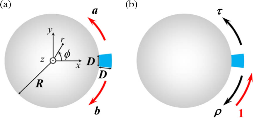
For simplicity, we consider a 2D cylindrical microcavity [18,38] [invariant along the -axis, as sketched in Fig. 1(a)] and the developed model applies as well 3D structures (such as microdisk [39] or microtoroid [4] resonators). A sectorial nanoparticle (centered at with a side length ), whose geometry is chosen to facilitate the calculation, is adsorbed on the surface of the microcavity (with a radius ). The refractive indices of the nanoparticle, the cavity, and the surrounding medium take values 1.59 (polystyrene), 1.45 (silica), and 1 (air), respectively. The cavity is assumed to be excited by an external source, and the interaction between the cavity and exciting device (such as tapered fiber [4] or prism [20]) is neglected [15,19].
Figure 1.(a) Schematic of a -invariant cylindrical microcavity with a nanoparticle (blue sector) adsorbed on its surface. and denote the complex amplitude coefficients of the two counterpropagating APMs matched to the resonant mode. (b) Scattering coefficients and characterizing the reflection and transmission of the APM at the nanoparticle.
Without the perturbation of the nanoparticle, each pair of degenerate WGMs are formed by two matched counterpropagating APMs with a phase shift of over a azimuthal angle [31,32]. The WGMs with different complex resonance frequencies can be indexed as , with TE/TM denoting polarization (electric/magnetic vectors along the invariant direction), being the radial number (corresponding to APMs with different propagation constants along the azimuthal direction) and being the azimuthal number. With the adsorption of a nanoparticle, the degeneracy of the WGMs is lifted, which results in a pair of splitting resonant modes [4,5,8,10]. Next we will try to build up an analytical model to reproduce the splitting resonant modes by considering an intuitive multiple-scattering picture that incorporates the elastic transmission and reflection of APMs at the particle. In the model only two matched counterpropagating APMs (corresponding to the unperturbed degenerate WGMs) are considered, and all other mismatched APMs (corresponding to other different WGMs) are neglected. As sketched in Fig. 1(a), we use and to denote the unknown complex amplitude coefficients of the APMs propagating in positive and negative directions, respectively. To determine and , a set of coupled-APM equations can be written: where and are defined as the reflection and transmission coefficients of the APM at the particle that is assumed to be mirror-symmetric about [as sketched in Fig. 1(b)], respectively, is the phase shift factor of the APM traveling azimuthally over one round of the cavity, ( and being the frequency and the speed of light in vacuum, respectively), and is the complex effective index of the APM that is a leaky waveguide eigenmode (with leaky loss so that is generally a complex number) [40]. Here is obtained with a full-wave aperiodic Fourier modal method (a-FMM) [41–43], and and are obtained as the scattering-matrix elements with the a-FMM [44] (more details about the calculation of , , and under cylindrical coordinate system can be found in Appendix A, and some earlier work on the calculation of can be found in Ref. [31]). The first-principle calculation of all quantities used in the model ensures a solid electromagnetic foundation and thus quantitative prediction of the model. Equation (1a) is written in view that the APM propagating along the positive direction (with coefficient ) results from two contributions, one contribution from the transmission () of itself (with coefficient and a one-round phase shift factor ) at the particle, and the other contribution from the reflection () of the counterpropagating APM (with coefficient and a phase shift factor ) at the particle. Equation (1b) is written in a similar way. Equation (1) can be understood in a rigorous sense under a cylindrical coordinate system, as illustrated in Fig. 5(b) in Appendix A. To obtain nontrivial solutions of Eq. (1), which represent the resonant modes, the determinant of the coefficient matrix should be zero, which yields Equation (2) can be used to determine the complex resonance frequency of the pair of splitting resonant modes. Substituting Eq. (2) into Eq. (1), one obtains [corresponding to in Eq. (2)] or (corresponding to ), which is defined as a symmetric (S) or anti-symmetric (AS) mode [4,20] (with electrical vector being symmetric or anti-symmetric about ). For the special case without the particle, i.e., and , Eq. (2) reduces to , indicating that the one-round phase shift of the APM is multiples of [31,32], which forms the two unperturbed degenerate WGMs. For the case with the presence of the particle, similar physical meaning preserves for Eq. (2) by additionally incorporating the particle-induced phase change of APMs [45]. Equations (1) and (2) explicitly show that the degeneracy of the WGMs preserves if , meaning that the particle-induced coupling between the two unperturbed counterpropagating WGMs (formed by the two matched APMs), which are widely adopted in current theoretical formalisms [20–22,26,37], is realized via the reflection of APMs () [35]. Here, note that the fields of the two counterpropagating APMs matched to the splitting modes are almost identical to the fields of the two counterpropagating unperturbed WGMs except for some subtle difference: they correspond to slightly different complex resonance frequencies; within the deep subwavelength range of the nanoparticle, the matched APMs have no definition (Appendix A), while the unperturbed WGMs have [15,20,26,38]. The latter difference arises from the different nature of the APM and the WGM: the APM is a waveguide mode (corresponding to a dispersion curve describing the dependence of on frequency, see more details in Appendix A) [31,33–36,40], while the WGM is a resonant eigenmode (corresponding to a single complex eigenfrequency) [19,20,26]. To seek the solution, Eq. (2) can be rewritten as where , . Details for deriving the approximate equality in Eq. (3) can be found in Appendix B. Thanks to the weak dependence of , , and on frequency [and thus the weak dependence of the right side of Eq. (3) denoted as ], the transcendental Eq. (3) can be solved with the contractive mapping method [46] with the iteration formula , which converges fast and is fairly insensitive to the initial value [more details on solving Eq. (3) can be found in Appendix B]. In fact, a crude evaluation of the complex resonance frequency can be obtained by calculating at a certain frequency.
3. RESULTS AND DISCUSSION
With the complex eigenfrequency obtained, we can then determine the several key parameters in sensing applications [1–13], the frequency shift ( being the complex resonance frequency of the unperturbed WGM), the -factor and the frequency splitting ( and being the complex resonance frequencies of the S-mode and the AS-mode, respectively). The mode splitting can be resolved only if is greater than the sum of the linewidths of the S-mode and the AS-mode [20,37]. Note that the experimentally resolvable splitting also depends on the external -factor [4] related to the fiber WGR coupling.
Now we check the validity of the model. We first consider the pair of splitting resonant modes arising from the unperturbed WGM for cavity radius μ. The quantities , , and as a function of nanoparticle size are plotted in Figs. 2(a), 2(b), and 2(f), respectively, which are obtained with the finite element method (FEM) using COMSOL Multiphysics Software (circles), the original model (solid curves), and the simplified model (dashed curves). Here the original model and the simplified model refer to the equality and the approximate equality in Eq. (3), respectively. It is seen that the prediction of the original model and that of the simplified model have no observable difference (the dashed curves are in fact completely superimposed by the solid curves), and both predictions are quite accurate compared with the FEM numerical results, except for slight deviations for large particles (), which will be explained later. Similar accuracy of the model can be observed for ( close to ) and ( over ) modes with μ and 20 μm, respectively (Fig. 7 in Appendix B).
Figure 2.(a) Frequency shift [relative to the unperturbed WGM with resonance frequency ] and (b) -factor of S-mode (blue) and AS-mode (red) as a function of nanoparticle size . Inset in (b) shows (dotted curves) and (dashed–dot curves). (c)–(e) , , and of the resonant modes solved for different (the solid and dashed curves corresponding to left and right axes, respectively, the blue and red curves corresponding to the S-mode and the AS-mode, respectively). (f) (characterizing the resolvability of mode splitting) for different . The inset shows details for small particle sizes. In (a), (b), and (f), the solid curves, dashed curves (completely superimposed by the solid curves), and circles represent the predictions of the original model, the simplified model, and the FEM numerical results, respectively.
As shown in Figs. 2(a) and 2(b), the redshift () of the resonance frequency increases and the -factor decreases with the increase of nanoparticle size [15,47]. To achieve an understanding, analytical expressions of and can be obtained from Eq. (3): where is the resonance frequency of the unperturbed WGM. In Eq. (4), and are dependent on and frequency [expressed as , ], while is independent of , with taking the value of eigenfrequency , which is further dependent on . In view of the weak dependence of , , and on frequency , we obtain , , and approximately independent of [as confirmed by Figs. 2(c)–2(e)]. Therefore, Eq. (4a) indicates that the frequency shift is simply proportional to . Physically, represents the phase change of the two counterpropagating coherently incident APMs when scattered at the nanoparticle [45] for the S-mode and for the AS-mode. As shown by the numerical results in Fig. 2(c), such scattering-induced phase change remains positive and increases monotonously with the increase of particle size. Blueshift () may happen [4,24,47] if the refractive index of the particle is smaller than that of its surrounding medium (Fig. 8 in Appendix B). The positive (resp. negative) and their monotonous dependence on can be understood by considering that the incident APM hops over the nanoparticle via another APM with a higher (resp. lower) effective index (Appendix B), which provides insight into the increase of the effective optical path length [11,48] or average index [47] that causes the mode shift.
Concerning Eq. (4b), the first and the second terms correspond to -factors related to the propagation loss (, composed of leaky loss and absorption loss of APMs, the latter being in fact excluded by considering lossless material here) and the particle-scattering induced loss () [9,49,50], which are shown in the inset of Fig. 2(b) and exhibit a crossing point . It is seen that dominates over for and vice versa for . Comparison between the insets of Figs. 2(b) and 7(b) (with the same radial number 1 of APMs) shows that becomes smaller for higher factors (with larger azimuthal number), which can be understood in view of the decrease of and the approximate invariance of . A lower -factor for a larger can be understood in view that holds due to the energy conservation [45] and decreases with the increase of the scattering-induced energy loss for larger [as confirmed by Fig. 2(d)]. This analysis shows that the particle-induced coupling between the unperturbed WGMs and the free-space radiation modes widely adopted in current theoretical formalisms [20–22,26,37] is realized via the scattering-induced free-space radiation of APMs. Note that if we define so that the phase shift factor of APM can be expressed as with denoting the arc length, then is reasonably between the refractive indices 1 and 1.45 of air and silica.
Due to the different amounts of frequency shift between the S-mode and AS-mode, the phenomenon of mode splitting [4,20] emerges if . Figure 2(f) shows that, with the increase of particle size , first increases from negative (no mode splitting but mode shift [1,9] and broadening [7,9,12] with high -factors for , below the red dashed–dot line) to positive values (with mode splitting), and then decreases to large negative values (no mode splitting with low -factors for ). This observation is consistent with earlier results [15,51]. Simple analytical expressions of and can be obtained from Eq. (3):
Now we look at the case of TE resonant modes. Numerical results fully parallel with those in Fig. 2 but corresponding to unperturbed WGM are shown in Fig. 3. In sharp contrast with TM modes, it is seen that the frequency shift and -factor of the TE AS-mode (red curves) are almost unchanged until the nanoparticle size increases to large values (). This phenomenon earlier discussed in Ref. [19] in terms of field symmetries under different polarizations can be explained here with a symmetry relation [52] of APM scattering coefficients. The symmetry relation derives from a mirror symmetry of the particle-induced scattered electric field about , which arises from the mirror symmetry of the incident APM electric field (with only component under TE polarization) within the deep subwavelength range of the nanoparticle. As numerically confirmed by the red curves in Figs. 3(c) and 3(d), holds for small values of but becomes less accurate for large values of due to the vanishing of the symmetry. Inserting into the right side of Eq. (3), we simply obtain for the AS-mode, which is exactly the complex resonance frequency of the unperturbed WGM in absence of the nanoparticle . Our interpretation here provides a new viewpoint to understand the preservation of resonance in terms of the scattering properties of APMs at the nanoparticle, in comparison with the viewpoint in terms of the location of the nanoparticle at the node of the anti-symmetric resonant mode [4,19,20]. For TE S-mode or TM modes, the resonance frequency and -factor change with the particle size because no similar symmetry relation works. The conclusions here are fully consistent with those from the rigorous ab initio analysis [18,19] but are only partially consistent with those from the semi-QED theory [20] for which the preservation of one resonance is independent of mode polarization.
Figure 3.Same as Fig. 2 but for the resonant modes corresponding to the unperturbed WGM [with resonance frequency ].
The previous results show that, for considerably large particle size (), the model exhibits observable deviation from the numerical FEM results. This deviation unveils a fact that, besides the matched APMs considered in the model, other mismatched APMs also have contributions to forming the resonant mode, especially for large particles. This could be surprising because, in current theoretical formalisms [4,20–22,26,38], the resonant mode is commonly treated as a superposition of two unperturbed counterpropagating WGMs (formed by the matched APMs). The contribution of mismatched APMs implies the existence of the cross coupling between the unperturbed WGMs and other different WGMs. To see this contribution directly, we show the residual field (denoted by ) that excludes the matched APMs’ field () contained in the total field () of the resonant mode, i.e., . Details for calculating the residual field with the mode orthogonality can be found in Appendix C. As shown by the numerical results in Fig. 4 for two particle sizes ( and 500 nm), the residual field is much weaker than the matched APM field for both particle sizes, which explains the high accuracy of the model. On the other hand, the residual field for is much stronger than that for . In more detail, the mean electric-field intensities of the residual field at the outer surface of the microcavity (excluding the range of the particle where the APM has no definition) are 0.0018 and 0.0458 for and 500 nm, respectively, which explains the lower accuracy of the model for larger particle sizes.
Figure 4.Electric-field intensities (a) and (b) of the APM field and of the residual field for the TM S-mode (already shown in Fig. 2) with particle size . The APM field is artificially extended into the deep subwavelength range of the nanoparticle where the APM has no definition. (c) and (d) The same as (a) and (b) but for a larger . Here the electric radial-components of the two matched counterpropagating APMs are normalized to have at μ and for the two particle sizes, so that a direct comparison of their corresponding residual fields can reflect the weight of the residual field relative to the matched APM field (or to the total field).
An intuitive and quantitative model for the pair of particle-induced splitting resonant modes of WGRs is built up by considering a dynamical multiple-scattering process of two counterpropagating APMs matched to the resonant modes. Simple analytical expressions of the resonance frequency and the -factor of the splitting modes in terms of the APM scattering coefficients at the nanoparticle are derived. The model unveils explicit relations between the particle-induced phase change and energy loss of the APM and the crucial phenomena of mode shift, mode broadening, and mode splitting for ultrahigh-sensitivity sensing applications; the model further explains the polarization-dependent preservation of one resonance and the particle-dependent redshift or blueshift with the symmetry and phase change in the scattering of APMs, respectively. The particle-induced coupling between the two counterpropagating unperturbed WGMs and the coupling between the WGMs and free-space radiation modes are shown to arise from the particle-induced reflection and free-space radiation of the APM, respectively. Contribution of mismatched APMs (corresponding to WGMs other than the unperturbed WGMs) to forming the splitting resonant modes especially for large particles is identified. The present model can be readily extended to more complex cases such as asymmetric particles [17], resonant plasmonic particles [12,24], or particle ensembles [21,38,53].
APPENDIX A: CALCULATION OF THE COMPLEX EFFECTIVE I
In the main text, the resonant mode of the whispering gallery microcavity with the adsorption of a nanoparticle is reproduced by the model with the use of the matched azimuthally propagating mode (APM) and their scattering coefficients at the nanoparticle. The APMs and their scattering coefficients can be calculated by solving the Maxwell’s equations under the cylindrical coordinate system defined as where are the rectangular Cartesian coordinates, and are the radial, axial, and azimuthal coordinates with , , and . The minus of in Eq. (A1) is to ensure that forms a right-handed coordinate system. Based on the well-known form invariance of Maxwell’s equations under curvilinear coordinate systems [40], the covariant Maxwell’s equations under have the same form as those under but with a transformation of relative permittivity and permeability and with the covariant electromagnetic field components as the unknown. For instance, the scalar relative permittivity and permeability are transformed to be tensors and that represent an electrically and magnetically anisotropic medium. Here is the metric tensor and with and . From Eq. (A1), one can obtain and . Here note that the given by Eq. (A2) is invariant, and in view that and are both invariant for the considered microcavity, we then conclude that the relative permittivity and permeability tensors and in the covariant Maxwell’s equations are both invariant. Therefore, as sketched in Figs. 5(a) and 5(b), the cylindrical cavity under is mapped to be an equivalent straight ( invariant) waveguide under , and the sectorial nanoparticle is mapped to be a rectangular one.
Figure 5.(a) Diagram of the cylindrical microcavity with adsorption of a nanoparticle under the Cartesian coordinate system . and are the complex amplitude coefficients of the two counterpropagating APMs matched to the resonant mode considered in the model. (b) The system is mapped to be an equivalent straight waveguide with adsorption of a periodic array of nanoparticles along the direction under the extended cylindrical coordinate system . (c) Scattering problem for defining the reflection and transmission coefficients and of the matched APM at the nanoparticle. (d) Artificial periodic structure for applying the a-FMM to model the scattering problem shown in (c).
To model the equivalent straight waveguide in the presence of a nanoparticle, here we use the aperiodic Fourier modal method (a-FMM) [41] to solve the covariant Maxwell’s equations, in which the propagation direction of APMs is chosen as the propagation direction of waveguide eigenmodes to be solved with the a-FMM. Because all spatial variables in the a-FMM should take values over , we adopt a mirror symmetry of the electric field vector about the plane , and a periodic boundary condition with a period of along the direction [54], so that, for such an extended cylindrical coordinate system, and can take values over . Interestingly and importantly, under the extended cylindrical coordinate system, the cylindrical cavity with a single adsorbed nanoparticle [as sketched in Fig. 5(a)] is mapped to be an equivalent straight ( invariant) waveguide with adsorption of a periodic array of nanoparticles along the direction [as sketched in Fig. 5(b)]. Keeping this equivalent structure in mind, Eq. (2) of the model in the main text can be understood in a rigorous sense as a description of the scattering process of the APM at the nanoparticle centered at with the presence of the particle array, as illustrated in Fig. 5(b). Consequently, the transmission and reflection coefficients and of the matched APM used in the model can be rigorously defined by the scattering problem, as sketched in Fig. 5(c), where a single particle located at is illuminated by an up-going incident APM, which excites a transmitted and a reflected APMs with coefficients and .
Now our task reduces to solving the scattering problem, as sketched in Fig. 5(c), with the a-FMM [41]. The a-FMM is a generalization of the well-known rigorous coupled wave analysis (RCWA) by additionally incorporating perfectly matched layers (PMLs) to handle the outgoing-wave boundary condition at infinity. The PMLs are performed as a complex coordinate transformation [41,54] that maps the infinite range of the physical space along -direction into a finite supercell of numerical space with . Then an artificial periodic array of the supercell is built up along the direction, as sketched in Fig. 5(d), so that the electromagnetic field can be expanded upon Fourier basis along the direction. Then the algorithm of RCWA for electrically and magnetically anisotropic media [43] can be applied to this artificial periodic system. In the a-FMM, the Fourier expansion of the electromagnetic field is inserted into the differential Maxwell’s equations under coordinates , and a resultant system of linear ordinary differential equations for the unknown Fourier coefficients are obtained, which are then integrated analytically in each invariant layer to express the field in terms of the waveguide eigenmodes that propagate along direction. For instance, the radial component of the electric field can be expressed as In Eq. (A3), is the truncated harmonic number of the Fourier series, , and the system is assumed to be independent. In Eq. (A4), is the number of the solved waveguide eigenmodes (i.e., APMs), is the propagation constant of the th APM and is obtained by solving the eigenvalues of the coefficient matrix of the resultant linear ordinary differential equations, is the corresponding eigenvector and determines the field distribution of the th APM, and are the coefficients of the th APM that propagates in positive (counterclockwise) and negative (clockwise) directions, respectively, and is the thickness of the invariant layer. Here and are determined by matching the continuous boundary condition of tangential electromagnetic field components at interfaces between adjacent invariant layers with the use of a stable scattering-matrix algorithm [55]. By substituting Eq. (A4) into Eq. (A3), is finally expressed as a superposition of counterclockwise and clockwise-propagating APMs: where and represent the counterclockwise and clockwise-propagating APMs in each invariant layer, respectively.
To solve the scattering problem as sketched in Fig. 5(c) with the a-FMM, the structure can be divided into three invariant layers, i.e., a middle layer with the nanoparticle sandwiched by top and bottom semi-infinite layers. The matched APMs considered in the model can be solved as the waveguide eigenmodes in the top or bottom semi-infinite layers. Note that the matched APMs have no definition within the middle invariant layer of the nanoparticle, as mentioned in the main text before Eq. (3). Then, by sending an up-going matched APM from the bottom invariant layer, the reflection and transmission coefficients and of the matched APMs at the nanoparticle can be solved as the coefficient of the matched APM in the bottom layer and of the matched APM in the top layer [see Eq. (A5)], respectively.
APPENDIX B: SOME DETAILS FOR SOLVING RESONANT MODE
We first show the derivation process of the simplified model [the approximate equality of Eq. (3) in the main text]. As done in the main text, we define and , and then the equality of Eq. (3) in the main text becomes where the two approximate equalities are obtained by neglecting the higher-order small quantities and compared with and .
As mentioned in the main text, the complex eigenfrequency of the resonant mode can be obtained by solving Eq. (3) in the main text with the contractive mapping method [46]. The iteration formula is with denoting the right side of Eq. (3). As shown in Figs. 6(a)–6(b), the obtained series of converge fast to (with about two or three iterations), and the converged solution is fairly insensitive to the initial value . This virtue is attributed to the weak dependence of on that arises from the weak dependence of , , and on , as confirmed numerically by Figs. 6(c)–6(f) [note that the frequency range shown in Figs. 6(c)–6(f) is 2 orders of magnitude larger than the frequency shift range shown in Figs. 2(a) and 3(a) in the main text]. In fact, by assuming an extreme case that is independent of , Eq. (3) in the main text simply provides an analytical solution of the complex eigenfrequency.
Figure 6.(a)–(b) Iteration process of solving the complex eigenfrequency of the resonant mode (blue and red curves for S-mode and AS-mode, respectively) in Fig. 2 in the main text, with adsorbed nanoparticle size . represents the number of iteration, and the initial value of iteration is (corresponding to wavelength 1.5 μm). The inset in (a) is a magnified view of the iteration curves. (c)–(f) , , , and plotted as a function of frequency (the shown frequency range corresponding to a wavelength range 1.3–1.7 μm).
Figure 7.(a)–(f) The same as Fig. 2 in the main text but for the resonant mode corresponding to the unperturbed WGM [with resonance frequency ] supported by the microcavity with radius μ. (g)–(h) The same as Figs. 2(a)–2(b) in the main text but corresponding to WGM with and μ.
Figure 8.Blueshift relative to the unperturbed (a) and (c) WGMs plotted as a function of nanoparticle size . The results are obtained for a refractive index 0.59 of the adsorbed particle that is lower than the refractive index of the particle’s surrounding medium of air. All other parameters are the same as those in Fig. 2 of the main text. (b) and (d) show the negative values of for different corresponding to (a) and (c), respectively. The blue and red curves show the results of the S-mode and the AS-mode, respectively.
Here we provide details on the calculation of the residual field that excludes the field of the APMs matched to the resonant mode, as shown in Fig. 4 in the main text. The residual field is defined as , where is the total field of the resonant mode that can be obtained with the full-wave FEM calculation, and is the field of the matched APMs that propagate along positive ( with complex amplitude coefficient ) and negative ( with coefficient ) azimuthal directions. and can be calculated with the a-FMM (as explained in Appendix A). Thus the calculation of reduces to the extraction of and from . For that purpose, it is conceptually clear to consider the equivalent straight waveguide with adsorption of a periodic array of nanoparticles along the direction [as sketched in Fig. 5(b)] under the extended cylindrical coordinate system , rather than considering the original cylindrical cavity with adsorption of a single nanoparticle under rectangular coordinates [as sketched in Fig. 5(a)].
According to the completeness theorem of normal modes supported by a straight waveguide [40], the total field of the resonant mode out of the range of the nanoparticle can be expressed as a linear superposition of forward (counterclockwise) and backward (clockwise) propagating normal modes: where represents both the electric and the magnetic vectors, and represent the complex amplitude coefficients of the corresponding forward () and backward () propagating normal modes, , and the system is assumed to be independent. To determine the mode expansion coefficients in Eq. (C1), one resorts to a general non-complex-conjugate form of orthogonality relations for normal modes [40]: where represents the Kronecker delta, and a bilinear form is defined as whose value is independent of [40]. Compared with the classical complex-conjugate form of orthogonality relations [40], Eq. (C2) apply to the more general case that the normal modes possess propagation loss [i.e., ], which is always true for APMs because they are leaky modes [40] and is true if the waveguide contains lossy material. In Eq. (C3), are the covariant components of electric vector under cylindrical coordinates and are defined by where are unit-length basis vectors [as sketched in Fig. 5(a)], which are convenient for manipulations. Then the corresponding components and are related by , , . The components of magnetic vector in Eq. (C3) are defined in a similar way.
Calculating the bilinear forms and with Eq. (C1) inserted in and applying the orthogonality relations in Eq. (C2), one can obtain the mode expansion coefficients With the use of Eq. (C5), the coefficients and of the counterclockwise and clockwise-propagating APMs contained in their matched resonant mode can be obtained.
Junda Zhu, Ying Zhong, Haitao Liu, "Impact of nanoparticle-induced scattering of an azimuthally propagating mode on the resonance of whispering gallery microcavities," Photonics Res. 5, 396 (2017)