• Photonics Research
  • Vol. 10, Issue 1, 68 (2022)
A. S. Lal Krishna, Sruti Menon, Asish Prosad, and Varun Raghunathan*
Author Affiliations
  • Department of Electrical Communication Engineering, Indian Institute of Science, Bangalore 560012, India
  • show less
    DOI: 10.1364/PRJ.442650 Cite this Article Set citation alerts
    A. S. Lal Krishna, Sruti Menon, Asish Prosad, Varun Raghunathan. Mid-infrared quasi-BIC resonances with sub-wavelength slot mode profiles in germanium-based coupled guided-mode resonance structures[J]. Photonics Research, 2022, 10(1): 68 Copy Citation Text show less
    (a) Schematic of the c-GMR structure showing angle of incidence AOI (θ, φ), and dimensions. Simulated transmission contour as a function of wave vector and x component of wave vector for c-GMR structure (b) without SiN layer and (c) with SiN layer. Insets show the zoomed-in views of corresponding BICs across the white square region. Wave vector is represented as inverse of wavelength in micrometers. Simulated transmission spectra considering plane wave excitation for c-GMR structures (d) without SiN layer and (e) with SiN layer for AOIs of 0°, 1°, and 5°.
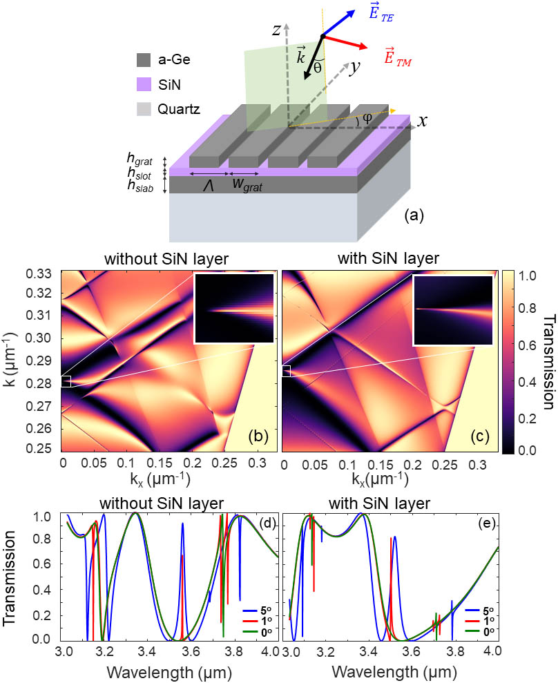
    Fig. 1. (a) Schematic of the c-GMR structure showing angle of incidence AOI (θ, φ), and dimensions. Simulated transmission contour as a function of wave vector and x component of wave vector for c-GMR structure (b) without SiN layer and (c) with SiN layer. Insets show the zoomed-in views of corresponding BICs across the white square region. Wave vector is represented as inverse of wavelength in micrometers. Simulated transmission spectra considering plane wave excitation for c-GMR structures (d) without SiN layer and (e) with SiN layer for AOIs of 0°, 1°, and 5°.
    Longitudinal component of electric field (|Ez|) along the xz plane for the c-GMR structure without SiN for AOI of (a) 0° and (b) 1°, and with SiN for AOI of (d) 0° and (e) 1°. Vertical line profile of |Ez| at x=0 and AOI of 1° for c-GMR structure: (c) without SiN and (f) with SiN. Mode-confinement factor (MCF) in different layers of the c-GMR structure as a function of: (g) varying AOI for fixed SiN thickness of 200 nm and (h) varying SiN height for fixed AOI of 1°.
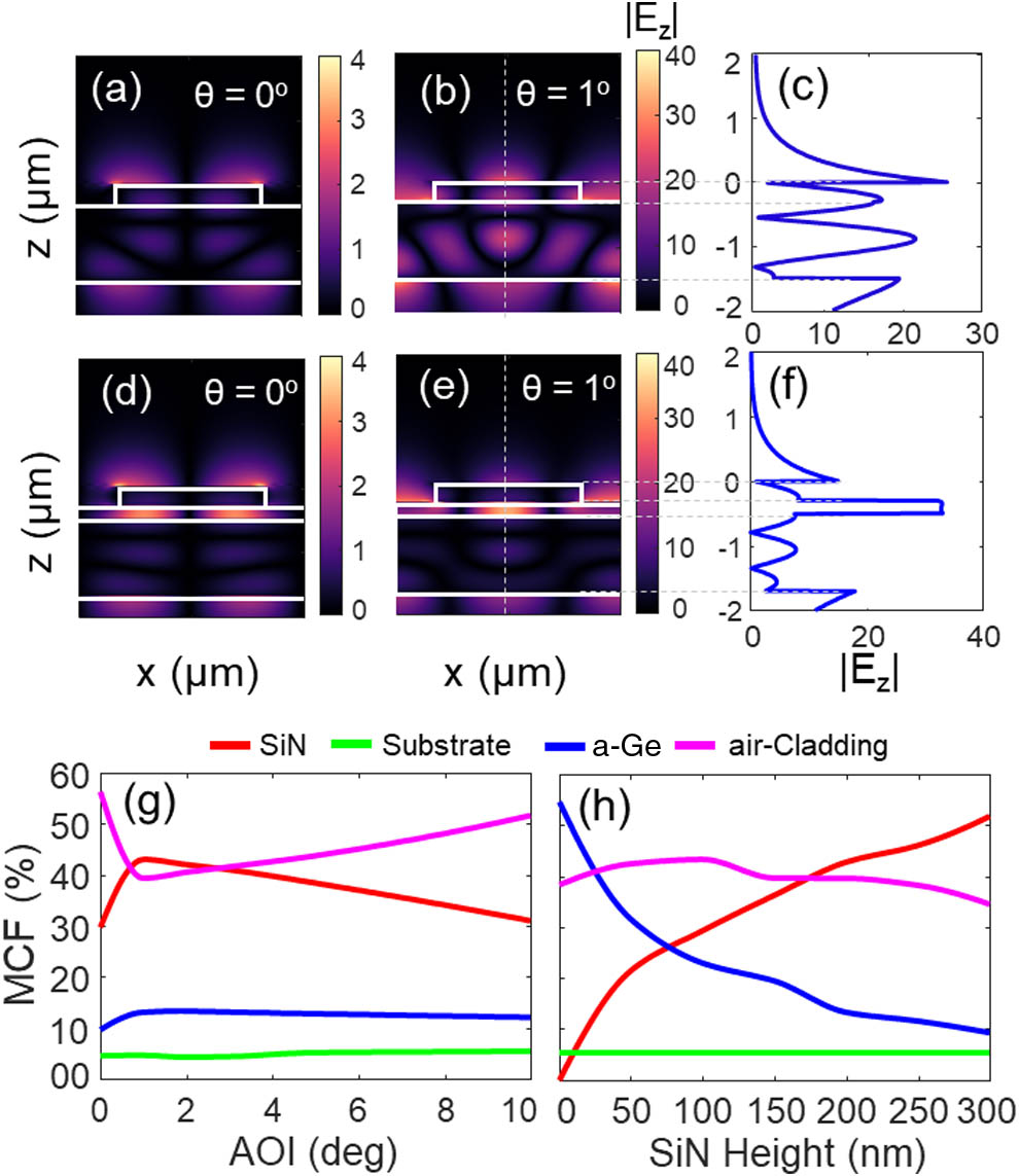
    Fig. 2. Longitudinal component of electric field (|Ez|) along the xz plane for the c-GMR structure without SiN for AOI of (a) 0° and (b) 1°, and with SiN for AOI of (d) 0° and (e) 1°. Vertical line profile of |Ez| at x=0 and AOI of 1° for c-GMR structure: (c) without SiN and (f) with SiN. Mode-confinement factor (MCF) in different layers of the c-GMR structure as a function of: (g) varying AOI for fixed SiN thickness of 200 nm and (h) varying SiN height for fixed AOI of 1°.
    (a) Photograph showing sample with fabricated device (highlighted in white box). SEM images showing device (b) cross section before grating fabrication and (c) top view of the grating structures. Scale bar is 2 μm. (d) AFM image showing grating etch depth and sidewall profile.
    Fig. 3. (a) Photograph showing sample with fabricated device (highlighted in white box). SEM images showing device (b) cross section before grating fabrication and (c) top view of the grating structures. Scale bar is 2 μm. (d) AFM image showing grating etch depth and sidewall profile.
    (a) Schematic showing GMR excitation under classical mounting condition with TM polarized Gaussian beam incidence. (b) Experimental and (c) simulated (with Gaussian beam excitation) transmission contour map as a function of wavelength and AOI. (d) Resonance peak wavelength shift as a function of AOI comparing experimental (red circles) and simulated data for plane wave (blue curve) and Gaussian beam (red curve) excitations.
    Fig. 4. (a) Schematic showing GMR excitation under classical mounting condition with TM polarized Gaussian beam incidence. (b) Experimental and (c) simulated (with Gaussian beam excitation) transmission contour map as a function of wavelength and AOI. (d) Resonance peak wavelength shift as a function of AOI comparing experimental (red circles) and simulated data for plane wave (blue curve) and Gaussian beam (red curve) excitations.
    Schematics showing the GMR excitation under (a) classical mounting and (b) full-conical mounting conditions with TM polarized Gaussian beam incidence. Experimental and simulated transmission spectra corresponding to (c), (e) classical and (d), (f) full-conical mounting, respectively. (g) Quality factor (left axis) as a function of AOI from experimental measurements for classical (red circles) and full-conical (blue circles) mounting. Comparison with simulations for plane wave excitation (red solid curve) and Gaussian beam excitation under classical (red dashed curve) and full-conical (blue dashed curve). The asymmetry parameter, α, as a function of AOI is also shown (right axis, black solid curve).
    Fig. 5. Schematics showing the GMR excitation under (a) classical mounting and (b) full-conical mounting conditions with TM polarized Gaussian beam incidence. Experimental and simulated transmission spectra corresponding to (c), (e) classical and (d), (f) full-conical mounting, respectively. (g) Quality factor (left axis) as a function of AOI from experimental measurements for classical (red circles) and full-conical (blue circles) mounting. Comparison with simulations for plane wave excitation (red solid curve) and Gaussian beam excitation under classical (red dashed curve) and full-conical (blue dashed curve). The asymmetry parameter, α, as a function of AOI is also shown (right axis, black solid curve).
    A. S. Lal Krishna, Sruti Menon, Asish Prosad, Varun Raghunathan. Mid-infrared quasi-BIC resonances with sub-wavelength slot mode profiles in germanium-based coupled guided-mode resonance structures[J]. Photonics Research, 2022, 10(1): 68
    Download Citation