• Photonics Research
  • Vol. 10, Issue 1, 68 (2022)
A. S. Lal Krishna, Sruti Menon, Asish Prosad, and Varun Raghunathan*
Author Affiliations
  • Department of Electrical Communication Engineering, Indian Institute of Science, Bangalore 560012, India
  • show less
    DOI: 10.1364/PRJ.442650 Cite this Article Set citation alerts
    A. S. Lal Krishna, Sruti Menon, Asish Prosad, Varun Raghunathan. Mid-infrared quasi-BIC resonances with sub-wavelength slot mode profiles in germanium-based coupled guided-mode resonance structures[J]. Photonics Research, 2022, 10(1): 68 Copy Citation Text show less

    Abstract

    We experimentally demonstrate a novel quasi-bound state in the continuum (BIC) resonance in the mid-infrared wavelength region with the resonant electric field confined as a slot mode within a low-refractive-index medium sandwiched between high-index layers. The structures studied here comprise coupled amorphous germanium guided-mode resonance (GMR) structures with a top one-dimensional grating layer and bottom uniform layer separated by a low-index silicon nitride layer. The slot-mode profile within the silicon nitride layer with mode field confinement >30% is achieved as a solution to the electromagnetic wave propagation through the coupled GMR structure with the dominant field component being perpendicular to the layers. The quasi-BIC resonance in symmetric 1D grating structures can be observed even at normal incidence when considering a realistic excitation beam with finite angular spread. The measured transmission peak is found to redshift (remain almost unchanged) under classical (full-conical) mounting conditions. The highest quality factor of 400 is experimentally extracted at normal incidence under a classical mounting condition with a resonance peak at 3.41 μm wavelength. Such slot-mode GMR structures with appropriately chosen low-index intermediate layers can find applications in resonantly enhanced sensing and active photonic devices.

    1. INTRODUCTION

    Resonant dielectric optical metasurfaces with high quality factors and frequency selective responses can be realized using guided-mode resonance (GMR) [1] and bound state in the continuum (BIC) phenomena [2,3]. True BIC resonances exhibit infinite quality factors and are inaccessible to external excitation. Such resonances can, however, be made accessible by making them quasi-BIC resonances using asymmetric structures for normal incidence excitation [4] or by using off-axis excitation for symmetric structures [5]. Quasi-BIC resonances have been utilized for realizing resonant metasurface-based lasers [6], photoluminescence enhancement [7], nonlinear optical enhancement from both dielectric structures [8] and two-dimensional materials integrated into the dielectric structures [9], sensing [10], and as chiral optical structures [11]. Such dielectric resonant metasurfaces operating in the mid-infrared (mid-IR) wavelength range are useful for realizing resonant optical filters, substrates for high-sensitivity surface-enhanced IR absorption, and nonlinear frequency upconversion devices. Quasi-BIC metasurfaces in the form of germanium-based tilted elliptical structures have been utilized for angle-resolved IR absorption spectroscopy [12]. Cuboid shaped unit cells with an additional asymmetric notch along one of the edges have been used to design high-quality-factor resonances in the 9–12 μm wavelength range [13]. One-dimensional (1D) grating structures exhibiting GMRs have been used to realize high-quality optical notch filters in the mid- and long-wave IR wavelength ranges [14,15]. Polarization independent filter characteristics have also been demonstrated using two-dimensional circularly symmetric unit cells [16] and stacked 1D sub-wavelength grating structures [17]. BIC resonances in close vicinity to finite-quality-factor GMRs have been theoretically studied in 1D sub-wavelength grating structures to understand their band edge properties [18,19]. The transformation of BIC resonances to leaky-mode resonance due to scattering and substrate leakage has also been reported [20].

    In addition to designing resonant metasurfaces to achieve resonances at specific spectral positions with high quality factors, it is necessary to tailor the resonant electric field profile to achieve strong field concentration either within the structure or outside. The resonant field engineering becomes essential in the context of sensing or nonlinear optical studies to ensure maximum interaction of the optical field with the material of interest. In this context, we present electromagnetic design, fabrication, and experimental study of novel slot-mode resonances in the mid-IR wavelength range with the electric field confined to the low-index medium sandwiched between high-index coupled-GMR (c-GMR) structures. The slot-mode profile with sub-wavelength mode field confinement is realized here in a silicon nitride (SiN) layer sandwiched in a c-GMR structure consisting of a top layer amorphous germanium (a-Ge) sub-wavelength grating structure and a bottom layer a-Ge un-patterned film. Such c-GMR structures have been proposed for use in realizing electromagnetically induced transparency (EIT) analogs [21,22], exhibiting a high-quality-factor transmission peak within a broad low-quality-factor resonance dip with field confinement in the high-index a-Ge un-patterned film. The electric field confinement with a low-index intermediate layer between two high-index layers has been studied theoretically in silicon grating/silicon dioxide/silicon c-GMR structures [23,24]. To the best of our knowledge, the present work is the first experimental report of such slot-mode resonances in any GMR or dielectric metasurface platform. Slot-mode profiles have been studied previously in conventional waveguide structures under transverse light coupling geometry [25]. However, such structures generally suffer from high coupling losses due to significant mode mismatch when coupled through fibers or other feeder waveguides. The confinement of the light as a slot mode within the low-index medium in a GMR device makes it easier to resonantly couple light into the low-index slot due to the presence of the top layer grating structures aiding in wave vector matching [1].

    2. COUPLED GMR STRUCTURE DESIGN

    A schematic of the c-GMR structure studied here is shown in Fig. 1(a). This consists of a low-refractive-index SiN layer sandwiched between a top a-Ge 1D sub-wavelength grating layer and a bottom a-Ge un-patterned slab layer on a low-index quartz substrate. The choice of the materials used in this stack is determined by the low optical absorption in the mid-IR spectral range and the ability to process these materials using standard clean-room fabrication techniques. The wavelength dependent refractive indices of the materials used here were obtained from ellipsometry measurements of a-Ge and SiN films used in the fabrication process. The c-GMR structure studied here is designed by optimizing the dimensions, namely, the lattice constant or pitch (Λ), the width of the grating (wgrat), thickness of the grating layer (hgrat), SiN layer (hslot), and a-Ge slab layer (hslab), as shown in Fig. 1(a), to achieve resonances at specific wavelength ranges of interest. First, we focus on quasi-BIC resonances in symmetric 1D grating structures with plane wave excitation of finite angular spread and varying angles of incidence (AOIs). The AOI, θ, is the tilt of the propagation axis with respect to normal direction (z axis), as shown in Fig. 1(a). The plane of incidence is also considered to be rotated about the z axis at an angle φ from the x axis, which is the grating vector direction. This results in exciting the grating under classical (φ=0°) and conical mounting (φ>0°) conditions, with φ=90° termed as full-conical mounting [26,27]. The polarization direction considered in this study is fixed as transverse magnetic (TM), where the magnetic field vector is perpendicular to the plane of incidence. The use of TM polarized excitation results in a strong out-of-plane field component (along z direction) within the structure [25,28], which ensures the excitation of the slot mode in the low-index intermediate layer. The c-GMR structures are designed using the finite-difference time-domain (FDTD)-based electro-magnetic wave propagation solver in ANSYS Lumerical FDTD [29].

    (a) Schematic of the c-GMR structure showing angle of incidence AOI (θ, φ), and dimensions. Simulated transmission contour as a function of wave vector and x component of wave vector for c-GMR structure (b) without SiN layer and (c) with SiN layer. Insets show the zoomed-in views of corresponding BICs across the white square region. Wave vector is represented as inverse of wavelength in micrometers. Simulated transmission spectra considering plane wave excitation for c-GMR structures (d) without SiN layer and (e) with SiN layer for AOIs of 0°, 1°, and 5°.

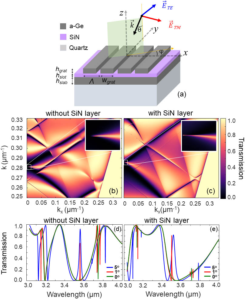
    Figure 1.(a) Schematic of the c-GMR structure showing angle of incidence AOI (θ, φ), and dimensions. Simulated transmission contour as a function of wave vector and x component of wave vector for c-GMR structure (b) without SiN layer and (c) with SiN layer. Insets show the zoomed-in views of corresponding BICs across the white square region. Wave vector is represented as inverse of wavelength in micrometers. Simulated transmission spectra considering plane wave excitation for c-GMR structures (d) without SiN layer and (e) with SiN layer for AOIs of 0°, 1°, and 5°.

    The photonic band diagrams equivalent for the c-GMR structures obtained from the plane wave excited transmission spectra plotted as a function of wave vector and x component of the wave vector for structures without and with the SiN layer are shown in Figs. 1(b) and 1(c), respectively. The wave vectors represent the inverse of the wavelength in units of μm−1. The dimensions of the GMR structure considered are Λ=2  μm, wgrat=0.5Λ, hgrat=300  nm, hslab=1.2  μm, and hslot=200  nm. The dimensions of the structure were optimized first in the absence of the SiN layer with varying a-Ge etch depths to achieve broad transmission dips in the 3 to 3.5 μm wavelength range for normal incidence with prominent quasi-BIC resonance for off-normal incidence. Following this, the addition of the SiN intermediate layer results in excitation of the low-index slot-mode profile with the optimum thickness chosen to achieve maximum fractional field confinement, as discussed below. The white dashed boxes show the spectral window of interest across in which the quasi-BIC resonance is observed, with a zoomed-in view of the region shown as an inset. Both a-Ge structures without the SiN layer, termed as the zero-contrast gratings (ZCGs) [30], and the c-GMR structure with the SiN intermediate layer exhibit BIC resonance at normal incidence at center wavelengths of 3.6 and 3.51 μm, respectively. With increasing excitation angles from normal incidence, clear resonance features of spectral width broadening as expected for quasi-BIC resonances, are observed, resulting in a reduced quality factor. The linear transmission spectra are also shown for AOIs of 0°, 1°, and 5° for the two structures in Figs. 1(d) and 1(e), respectively. Symmetry protected BIC resonances under plane wave normal incidence (green curve) with a broad transmission dip followed by narrow quasi-BIC resonances with increasing AOIs (blue and red curves) are observed. The ZCG quasi-BIC resonance is found to minimally shift with increasing AOIs. In contrast, the c-GMR structure exhibits a noticeable redshift in addition to spectral broadening with increasing AOIs. This points to the increased angular sensitivity of the transverse guided mode excited in the case of the a-Ge c-GMR structure with the low-index intermediate layer when compared to the a-Ge ZCG structure with increasing excitation angle. The sharp spectral feature observed in the 3.7 to 3.8 μm wavelength range is due to the excitation of an EIT-like high-quality-factor resonance [21,22] with the field concentrated in the un-patterned bottom a-Ge layer.

    The longitudinal electric field (z component) amplitude profiles corresponding to the a-Ge ZCG and a-Ge c-GMR with 200 nm SiN intermediate layers at their respective resonance wavelengths are shown in Figs. 2(a)–2(e), respectively. The field profiles are shown for plane wave excitation at 0° and 1° AOIs. The z component of the electric field is found to be the strongest for the a-Ge c-GMR structures. It is seen in Figs. 2(a) and 2(d) that the electric field profiles corresponding to the symmetry protected BIC exhibit characteristic double-lobe profiles that cannot be accessed through excitation with plane waves at normal incidence [19]. In contrast, quasi-BIC resonant mode profiles corresponding to AOIs of 1° shown in Figs. 2(b) and 2(e) exhibit a single-lobe mode profile that can be excited by plane waves at off-normal incidence. With the addition of a low-index SiN layer, the field profile is found to shift from the high-index a-Ge layer to the low-index SiN intermediate layer. This points to the excitation of a slot mode that is confined to the low-index medium sandwiched between high-index GMR structures. Vertical line-scan field profiles along the dashed line are also shown in Figs. 2(c) and 2(f). The slot mode supported in the 200 nm SiN layer in the a-Ge coupled GMR structure exhibits sub-wavelength confinement of light for the wavelength considered here with strong field concentration in the low-index region [25]. Clear slot-mode confinement can be observed even for SiN layer thicknesses as low as 1 nm.

    Longitudinal component of electric field (|Ez|) along the xz plane for the c-GMR structure without SiN for AOI of (a) 0° and (b) 1°, and with SiN for AOI of (d) 0° and (e) 1°. Vertical line profile of |Ez| at x=0 and AOI of 1° for c-GMR structure: (c) without SiN and (f) with SiN. Mode-confinement factor (MCF) in different layers of the c-GMR structure as a function of: (g) varying AOI for fixed SiN thickness of 200 nm and (h) varying SiN height for fixed AOI of 1°.

    Figure 2.Longitudinal component of electric field (|Ez|) along the xz plane for the c-GMR structure without SiN for AOI of (a) 0° and (b) 1°, and with SiN for AOI of (d) 0° and (e) 1°. Vertical line profile of |Ez| at x=0 and AOI of 1° for c-GMR structure: (c) without SiN and (f) with SiN. Mode-confinement factor (MCF) in different layers of the c-GMR structure as a function of: (g) varying AOI for fixed SiN thickness of 200 nm and (h) varying SiN height for fixed AOI of 1°.

    We compute the mode-confinement factor (MCF) to quantify the fraction of field intensity confined within a region of interest (ROI) in the unit cell of the coupled GMR as follows: MCF=ROI|E|2dxdzUnit cell|E|2dxdz,where the electric field intensity, |E|2, includes the sum of all three electric field intensity components. The MCF is plotted across various regions within the coupled-GMR structure unit cell as a function of AOI and SiN layer thickness as shown in Figs. 2(g) and 2(h), respectively. It is found that with increasing AOIs, the confinement of the slot mode in the 200 nm SiN layer increases from 30% to a maximum value of 42% for AOIs of 1° and subsequently decreases for higher AOIs. With the increase in AOI, the decrease in MCF in the low-index SiN layer is accompanied by field redistribution to the air region above the c-GMR structure. It is also found in Fig. 2(h) that an increase in SiN layer thickness for a fixed AOI of 1° results in the MCF in the SiN layer to monotonically increase at the expense of the field confinement in the a-Ge layer. The MCF in the SiN layer is the largest in comparison to the other regions in the c-GMR stack for a SiN layer thickness of 180  nm. In the design studies, we fix the SiN intermediate layer thickness as 200 nm to achieve large field confinement in the slot mode while at the same time ensuring sub-wavelength GMR mode confinement.

    3. GMR STRUCTURE FABRICATION

    A photograph of the fabricated a-Ge c-GMR structure is shown in Fig. 3(a). The structures were fabricated on a double-side-polished quartz substrate. The multilayer GMR stack consisting of an a-Ge slab layer, SiN layer, and a-Ge grating layer was deposited using plasma enhanced chemical vapor deposition (PECVD) at 350°C. The 1D a-Ge gratings were patterned using electron beam lithography. Reactive ion etching (RIE) using SF6 and C4F8 gas chemistry was used to transfer the mask patterns onto the a-Ge grating layer with a total etch height of the top a-Ge layer. A cross-sectional scanning electron microscope (SEM) image showing the layer stack before top layer grating fabrication is shown in Fig. 3(b). The average thicknesses of the individual layers are obtained as: hslab=1.13  μm, hslot=173  nm, and hgrat=283  nm. The fabricated grating profile as obtained using the top-view SEM image is shown in Fig. 3(c), with the Λ and wgrat of the grating line measured as 2 and 1.29 μm, respectively. The etch height of the grating layer measured using an atomic force microscope (AFM) profile is shown in Fig. 3(d), showing a fully etched top grating layer. The 1D grating structures show good etch profiles with vertical sidewalls that closely follow the designed structure dimensions with small deviations from the designed dimensions.

    (a) Photograph showing sample with fabricated device (highlighted in white box). SEM images showing device (b) cross section before grating fabrication and (c) top view of the grating structures. Scale bar is 2 μm. (d) AFM image showing grating etch depth and sidewall profile.

    Figure 3.(a) Photograph showing sample with fabricated device (highlighted in white box). SEM images showing device (b) cross section before grating fabrication and (c) top view of the grating structures. Scale bar is 2 μm. (d) AFM image showing grating etch depth and sidewall profile.

    4. EXPERIMENTAL RESULTS

    The transmission spectra for the c-GMR structures were experimentally characterized in a Fourier transform IR (FTIR) spectrometer (Perkin Elmer Frontier-FTIR). The sample was placed on a rotating holder to precisely vary the AOIs for both classical and conical mounting cases. A mid-IR polarizer was placed before the sample to illuminate the sample at TM polarization. The illumination spot at the sample is restricted to 1  mm using an aperture just before the sample. At the collection end, no aperture is placed to select a particular diffraction order, as the resonant structure is designed to operate in the zeroth order diffraction regime over a range of AOIs. Transmission spectra were obtained by normalizing the transmission measurements acquired at 1cm1 spectral resolution with and without the sample. Two types of sample mountings, i.e., classical and full-conical mountings, were employed for transmission measurements. The classical mounting setup was realized by placing the sample on the rotating holder such that the grating vector (along x direction) and plane of incidence (xz) are aligned in the same direction (φ=0°). Correspondingly, full-conical mounting was realized by aligning the plane of incidence perpendicular to the grating vector (φ=90°).

    A schematic of the classical mounting excitation of the grating structures is shown in Fig. 4(a). The experimentally measured transmission spectra collected across varying AOIs of ±10° are shown in Fig. 4(b) as a contour map. The evolution of quasi-BIC resonances with increasing spectral width and the redshift of the resonance peak are observed in the experimental measurements. For normal incidence, a finite spectral width resonance is still measured with the narrowest spectral width among the spectra experimentally obtained. For comparison with the experimental observations, a simulated transmission spectral contour map is shown in Fig. 4(c) obtained by considering finite size gratings with fabricated device dimensions and realistic Gaussian beam excitation rather than the ideal plane wave excitation. A divergence angle of 3° was used for the Gaussian beam based on actual experimental conditions used in the FTIR spectrometer. Good agreement is observed between the experimental and realistic simulation results. A comparison of the experimentally measured resonance peak positions (red circles) with simulations corresponding to the ideal plane wave (blue solid curve) and realistic excitation beam (red solid curve) excitations as a function of AOI is also shown in Fig. 4(d). Good agreement is obtained between the experimental and realistic simulation results except for a fixed offset in the resonance wavelength. The experimental measurement of the quasi-BIC resonances points to the fact that ideal symmetry protected BIC resonances can become quasi-BIC even at normal incidence when considering an appropriate angular spread for the excitation beam, thus making them accessible to external excitation.

    (a) Schematic showing GMR excitation under classical mounting condition with TM polarized Gaussian beam incidence. (b) Experimental and (c) simulated (with Gaussian beam excitation) transmission contour map as a function of wavelength and AOI. (d) Resonance peak wavelength shift as a function of AOI comparing experimental (red circles) and simulated data for plane wave (blue curve) and Gaussian beam (red curve) excitations.

    Figure 4.(a) Schematic showing GMR excitation under classical mounting condition with TM polarized Gaussian beam incidence. (b) Experimental and (c) simulated (with Gaussian beam excitation) transmission contour map as a function of wavelength and AOI. (d) Resonance peak wavelength shift as a function of AOI comparing experimental (red circles) and simulated data for plane wave (blue curve) and Gaussian beam (red curve) excitations.

    Gaussian beam excitation of the structures is modeled considering perfectly matched layer (PML) boundaries along x and z directions, while maintaining periodic boundary conditions along y direction (grating lines direction). This is termed here as a quasi-3D simulation. The use of a full-3D simulation model considering the exact Gaussian beam profile along the y direction would be the exact way to model the grating structures when compared to the quasi-3D model considered here. This would, however, require a significant increase in simulation time and memory requirement. A comparison of the quasi-3D and full-3D models for the classical mounting case showed good agreement between the obtained transmission spectra, justifying the use of a quasi-3D model in this study. Finite extent gratings with a grating number of 101 and y span of 1.0 μm are considered here in the quasi-3D model. Increasing the grating number or the y span above this did not result in a noticeable change in the transmission spectra obtained. The light source used in the FTIR spectroscopy is an incoherent, extended light source (e.g.,  globar source) with a typical measurement resolution of 1  cm1. The transmission spectra obtained in FTIR spectroscopy by reducing the optical resolution to 0.5  cm1 resulted in no changes in the transmission spectra, confirming that the measured resonances are not limited by the resolution of the instrument.

    Next, the evolution of the resonance characteristics under classical and full-conical mounting conditions as a function of increasing AOIs and the resulting quality factors of the resonances are discussed. Schematics of the GMR structure and the two mounting conditions are shown in Figs. 5(a) and 5(b). The experimental and simulated linear transmission spectra corresponding to the classical and full-conical mounting conditions are shown in Figs. 5(c)–5(f). Good overall agreement between the experimental and simulation results is observed for both classical and full-conical mounting cases with the latter exhibiting minimal angle dependence. The angle insensitivity of the resonances excited under full conical mounting is attributed to the negligible change in the diffracted order wave vector, which evanescently couples to the guided modes as a function of increasing AOIs [27]. The resonance spectral widths are found to be narrower in the simulations when compared to the experiments. This difference is attributed to fabrication imperfections, especially the deposited film and sidewall roughness, which can act as a scattering channel, lowering the resonance quality. Slight differences are observed in the transmission spectra between experimental and simulated results, especially at larger AOIs (>10°). This is attributed to the higher-order diffraction components present in the simulated case, which are typically rejected in the experiments by the placement of the detector far from the GMR structures in the FTIR instrument. The sharp resonance feature observed in the 3.7 to 3.8 μm wavelength range in Fig. 1(e) due to EIT-like resonance is absent in the experimental measurement or Gaussian beam simulations. This is due to the large angle sensitivity of this high-quality-factor resonance, which washes out under realistic excitation conditions.

    Schematics showing the GMR excitation under (a) classical mounting and (b) full-conical mounting conditions with TM polarized Gaussian beam incidence. Experimental and simulated transmission spectra corresponding to (c), (e) classical and (d), (f) full-conical mounting, respectively. (g) Quality factor (left axis) as a function of AOI from experimental measurements for classical (red circles) and full-conical (blue circles) mounting. Comparison with simulations for plane wave excitation (red solid curve) and Gaussian beam excitation under classical (red dashed curve) and full-conical (blue dashed curve). The asymmetry parameter, α, as a function of AOI is also shown (right axis, black solid curve).

    Figure 5.Schematics showing the GMR excitation under (a) classical mounting and (b) full-conical mounting conditions with TM polarized Gaussian beam incidence. Experimental and simulated transmission spectra corresponding to (c), (e) classical and (d), (f) full-conical mounting, respectively. (g) Quality factor (left axis) as a function of AOI from experimental measurements for classical (red circles) and full-conical (blue circles) mounting. Comparison with simulations for plane wave excitation (red solid curve) and Gaussian beam excitation under classical (red dashed curve) and full-conical (blue dashed curve). The asymmetry parameter, α, as a function of AOI is also shown (right axis, black solid curve).

    The quality factor of the resonances obtained in the experiments as a function of AOI and its comparison with simulations are shown in Fig. 5(g). The quality factor is extracted by fitting the resonance line shape to a Fano-resonance equation as given by [31] T=(a+b)21+b2,b=2(λλo)γ,where T is the transmission, a quantifies the resonance line shape profile (e.g.,  for Lorentzian line shape a=0), λ is the wavelength, λ0 is the center wavelength, and γ is the full-width at half maximum (FWHM) of resonance in wavelength. The asymmetry that transforms the BIC resonances to quasi-BIC for the symmetric unit-cell structures considered here is the AOI, with the asymmetry parameter, α [4], given as the inverse of the AOI. The quality factor exhibits inverse square dependence with α (black solid curve), which is in good agreement with plane-wave-based classical mounting studies (red solid curve). The ideal plane wave excitation case shows a large discrepancy when compared to the experimental results (red circles) and Gaussian beam excitation simulation (red dashed curve) for smaller excitation angles (<3°) due to the finite angular spread of the excitation. For larger AOIs, the agreement between the plane wave and Gaussian excitation cases is found to be better. The best quality factors achieved based on experimental measurements and simulations are 400 and 580, respectively, for normal incidence at quasi-BIC resonance wavelengths of 3.41 and 3.42 μm, respectively. The difference between the experiments and simulations is attributed to the spectral broadening of the resonances for the fabricated c-GMR structures. For the case of full-conical mounting, the experimental and simulated quality factors are shown by blue circles and blue dashed curves, respectively, with the quality factor remaining almost unchanged with respect to the change in AOI, as is expected from the conical mounting case and seen from the transmission spectra [shown in Figs. 5(d) and 5(f)]. At normal incidence, the quality factor obtained for the conical mounting case is found to be 200, which is lower than that of the classical mounting case. This difference in quality factor when compared to the classical mounting case is attributed to the difference in the measured resonance spectral characteristics when the grating and polarizer placed in the FTIR beam path are rotated by 90° for the full conical mounting case due to imperfect polarizer extinction.

    5. CONCLUSION

    We have presented electro-magnetic design, fabrication, and experimental demonstration of a novel a-Ge-based c-GMR structure with a slot-mode field profile confined in the intermediate low-index SiN layer sandwiched between a top a-Ge grating layer and a bottom a-Ge uniform layer, achieving transmission resonance peaks in the 3.4–3.6 μm wavelength range. The sub-diffraction slot-mode resonance field profiles are solutions to the electro-magnetic wave propagation in the c-GMR structure satisfying boundary conditions for the guided-mode field polarized perpendicularly to the layered stack. The quasi-BICs from the symmetric 1D a-Ge-based c-GMR structures are observed even at normal incidence when considering a realistic excitation beam with finite angular spread. A comparison of classical mounting with a full-conical mounting case shows angle insensitive resonance excitation for full-conical excitation. The quality factors extracted from the experimental transmission spectra are also found to be in good agreement with the realistic Gaussian beam excitation simulations. A maximum quality factor of 400 is observed for quasi-BIC resonance at normal incidence under the classical mounting condition for a resonance wavelength of 3.41 μm. The strong field confinement achieved in the low-index medium combined with the robust angle dependent spectral characteristics achieved under classical and conical mountings makes such quasi-BIC c-GMR structures unique when compared to previously studied evanescent-field-based GMR devices [32]. The c-GMR structures also enable simplified wave vector matched light coupling to the low-index slot mode when compared to conventional slot-waveguide devices. Such c-GMR structures supporting slot-mode profiles can potentially be integrated with low-index gain media [33] or suitable target media [34] for active photonic or sensing applications, respectively. The low-index intermediate layer can also be selectively removed to realize air-suspended GMR structures, similar to suspended silicon waveguides [35] to fill the slot region with analytes for sensing applications.

    Acknowledgment

    Acknowledgment. The fabrication work and characterization were carried out at the National Nanofabrication Centre (NNFC) and Micro Nano Characterization Facility (MNCF), respectively, at the Indian Institute of Science, Bangalore.

    References

    [1] S. S. Wang, R. Magnusson. Theory and applications of guided-mode resonance filters. Appl. Opt., 32, 2606-2613(1993).

    [2] D. C. Marinica, A. G. Borisov, S. V. Shabanov. Bound states in the continuum in photonics. Phys. Rev. Lett., 100, 183902(2008).

    [3] S. I. Azzam, A. V. Kildishev. Photonic bound states in the continuum: from basics to applications. Adv. Opt. Mater., 9, 2001469(2021).

    [4] K. Koshelev, S. Lepeshov, M. Liu, A. Bogdanov, Y. Kivshar. Asymmetric metasurfaces with high-Q resonances governed by bound states in the continuum. Phys. Rev. Lett., 121, 193903(2018).

    [5] K. Koshelev, G. Favraud, A. Bogdanov, Y. Kivshar, A. Fratalocchi. Nonradiating photonics with resonant dielectric nanostructures. Nanophotonics, 8, 725-745(2019).

    [6] A. Kodigala, T. Lepetit, Q. Gu, B. Bahari, Y. Fainman, B. Kanté. Lasing action from photonic bound states in continuum. Nature, 541, 196-199(2017).

    [7] L. Zhu, S. Yuan, C. Zeng, J. Xia. Manipulating photoluminescence of carbon G-center in silicon metasurface with optical bound states in the continuum. Adv. Opt. Mater., 8, 1901830(2020).

    [8] K. Koshelev, Y. Tang, K. Li, D. Y. Choi, G. Li, Y. Kivshar. Nonlinear metasurfaces governed by bound states in the continuum. ACS Photon., 6, 1639-1644(2019).

    [9] N. Bernhardt, K. Koshelev, S. J. U. White, K. W. C. Meng, J. E. Fröch, S. Kim, T. T. Tran, D. Y. Choi, Y. Kivshar, A. S. Solntsev. Quasi-BIC resonant enhancement of second-harmonic generation in WS2 monolayers. Nano Lett., 20, 5309-5314(2020).

    [10] S. Romano, G. Zito, S. Torino, S. Cabrini, I. Rendina, G. Coppola, G. Calafiore, E. Penzo, V. Mocella. Label-free sensing of ultralow-weight molecules with all-dielectric metasurfaces supporting bound states in the continuum. Photon. Res., 6, 726-733(2018).

    [11] A. Overvig, N. Yu, A. Alù. Chiral quasi-bound states in the continuum. Phys. Rev. Lett., 126, 073001(2021).

    [12] A. Leitis, A. Tittl, M. Liu, B. H. Lee, M. B. Gu, Y. S. Kivshar, H. Altug. Angle-multiplexed all-dielectric metasurfaces for broadband molecular fingerprint retrieval. Sci. Adv., 5, eaaw2871(2019).

    [13] S. Campione, S. Liu, L. I. Basilio, L. K. Warne, W. L. Langston, T. S. Luk, J. R. Wendt, J. L. Reno, G. A. Keeler, I. Brener, M. B. Sinclair. Broken symmetry dielectric resonators for high quality factor Fano metasurfaces. ACS Photon., 3, 2362-2367(2016).

    [14] J.-N. Liu, M. V. Schulmerich, R. Bhargava, B. T. Cunningham. Sculpting narrowband Fano resonances inherent in the large-area mid-infrared photonic crystal microresonators for spectroscopic imaging. Opt. Express, 22, 18142-18158(2014).

    [15] M. S. Mirotznik, N. Gupta, M. McElhiney, V. Carey. Long wave infrared tunable filter based on guided mode resonant effect. Proc. SPIE, 9855, 98550L(2016).

    [16] A. S. Lal Krishna, V. Mere, S. K. Selvaraja, V. Raghunathan. Polarization-independent angle-tolerant mid-infrared spectral resonance using amorphous germanium high contrast gratings for notch filtering application. OSA Contin., 3, 1194-1203(2020).

    [17] K. J. Lee, Y. H. Ko, N. Gupta, R. Magnusson. Unpolarized resonant notch filters for the 8–12 μm spectral region. Opt. Lett., 45, 4452-4455(2020).

    [18] Y. Ding, R. Magnusson. Resonant leaky-mode spectral-band engineering and device applications. Opt. Express, 12, 5661-5674(2004).

    [19] S. G. Lee, R. Magnusson. Band flips and bound-state transitions in leaky-mode photonic lattices. Phys. Rev. B, 99, 045304(2019).

    [20] Z. F. Sadrieva, I. S. Sinev, K. L. Koshelev, A. Samusev, I. V. Iorsh, O. Takayama, R. Malureanu, A. A. Bogdanov, A. V. Lavrinenko. Transition from optical bound states in the continuum to leaky resonances: role of substrate and roughness. ACS Photon., 4, 723-727(2017).

    [21] Y. Ding, R. Magnusson. Doubly resonant single-layer bandpass optical filters. Opt. Lett., 29, 1135-1137(2004).

    [22] S.-G. Lee, S.-Y. Jung, H.-S. Kim, S. Lee, J.-M. Park. Electromagnetically induced transparency based on guided-mode resonances. Opt. Lett., 40, 4241-4244(2015).

    [23] M. Shokooh-Saremi, R. Magnusson. Wideband leaky-mode resonance reflectors: influence of grating profile and sublayers. Opt. Express, 16, 18249-18263(2008).

    [24] M. Niraula, J. W. Yoon, R. Magnusson. Mode-coupling mechanisms of resonant transmission filters. Opt. Express, 22, 25817-25829(2014).

    [25] V. R. Almeida, Q. Xu, C. A. Barrios, M. Lipson. Guiding and confining light in void nanostructure. Opt. Lett., 29, 1209-1211(2004).

    [26] D. Lacour, G. Granet, J.-P. Plumey. Polarization independence of a one-dimensional grating in conical mounting. J. Opt. Soc. Am. A, 20, 1546-1552(2003).

    [27] Y. H. Ko, M. Niraula, K. J. Lee, R. Magnusson. Properties of wideband resonant reflectors under fully conical light incidence. Opt. Express, 24, 4542-4551(2016).

    [28] S. Menon, K. M. Jyothsna, V. Raghunathan. Silicon nitride based medium contrast gratings for generating longitudinally polarized resonant fields. Proc. SPIE, 11695, 116951P(2021).

    [29] Lumerical FDTD. Lumerical FDTD. https://www.lumerical.com/products/fdtd/

    [30] R. Magnusson. Wideband reflectors with zero-contrast gratings. Opt. Lett., 39, 4337-4340(2014).

    [31] M. F. Limonov, M. V. Rybin, A. N. Poddubny, Y. S. Kivshar. Fano resonances in photonics. Nat. Photonics, 11, 543-554(2017).

    [32] G. Pitruzzello, T. F. Krauss. Photonic crystal resonances for sensing and imaging. J. Opt., 20, 073004(2018).

    [33] R. Guo, B. Wang, X. Wang, L. Wang, L. Jiang, Z. Zhou. Optical amplification in Er/Yb silicate slot waveguide. Opt. Lett., 37, 1427-1429(2012).

    [34] C. A. Barrios, K. B. Gylfason, B. Sánchez, A. Griol, H. Sohlström, M. Holgado, R. Casquel. Slot-waveguide biochemical sensor. Opt. Lett., 32, 3080-3082(2007).

    [35] J. Soler Penades, A. Ortega-Moñux, M. Nedeljkovic, J. G. Wangüemert-Pérez, R. Halir, A. Z. Khokhar, C. Alonso-Ramos, Z. Qu, I. Molina-Fernández, P. Cheben, G. Z. Mashanovich. Suspended silicon mid-infrared waveguide devices with subwavelength grating metamaterial cladding. Opt. Express, 24, 22908-22916(2016).

    A. S. Lal Krishna, Sruti Menon, Asish Prosad, Varun Raghunathan. Mid-infrared quasi-BIC resonances with sub-wavelength slot mode profiles in germanium-based coupled guided-mode resonance structures[J]. Photonics Research, 2022, 10(1): 68
    Download Citation