• Photonics Research
  • Vol. 7, Issue 3, 341 (2019)
Tiecheng Wang, Zhixin Li, and Xiangdong Zhang*
Author Affiliations
  • Beijing Key Laboratory of Nanophotonics & Ultrafine Optoelectronic Systems, School of Physics, Beijing Institute of Technology, Beijing 100081, China
  • show less
    DOI: 10.1364/PRJ.7.000341 Cite this Article Set citation alerts
    Tiecheng Wang, Zhixin Li, Xiangdong Zhang. Improved generation of correlated photon pairs from monolayer WS2 based on bound states in the continuum[J]. Photonics Research, 2019, 7(3): 341 Copy Citation Text show less
    (a) Diagram of the photonic crystal slab-monolayer WS2-slab. The air holes are arranged in a square lattice with lattice constant l and the radius of the holes is r. The thicknesses of the photonic crystal slab and dielectric slab are denoted by d1 and d2, and the monolayer WS2 is put at the interface between the photonic crystal slab and the dielectric slab. (b) Schematic of the photon-pair generation process in the three-layer structure. The pump beam with frequency ωp and angle θp is incident on the three-layer structure, and due to the second-order nonlinear effect of the monolayer WS2, the signal field with frequency ωs and angle θs and the idler field with frequency ωi and angle θi are generated.
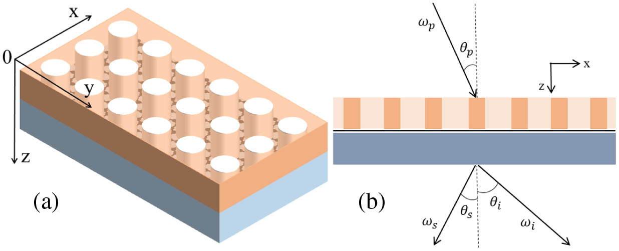
    Fig. 1. (a) Diagram of the photonic crystal slab-monolayer WS2-slab. The air holes are arranged in a square lattice with lattice constant l and the radius of the holes is r. The thicknesses of the photonic crystal slab and dielectric slab are denoted by d1 and d2, and the monolayer WS2 is put at the interface between the photonic crystal slab and the dielectric slab. (b) Schematic of the photon-pair generation process in the three-layer structure. The pump beam with frequency ωp and angle θp is incident on the three-layer structure, and due to the second-order nonlinear effect of the monolayer WS2, the signal field with frequency ωs and angle θs and the idler field with frequency ωi and angle θi are generated.
    (a), (b), and (c) show the transmission (t), reflection (r), and absorption (a) spectra for the three-layer structure as shown in Fig. 1, respectively. (d), (e) and (f) display the corresponding transmission (t′), reflection (r′), and absorption (a′) spectra, respectively.
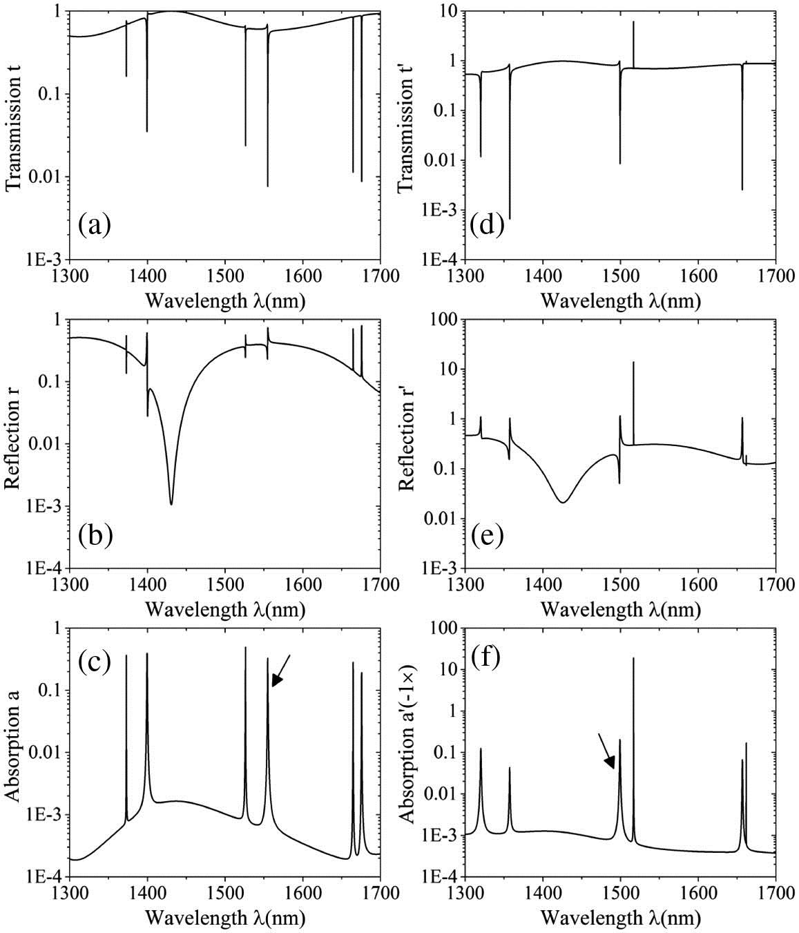
    Fig. 2. (a), (b), and (c) show the transmission (t), reflection (r), and absorption (a) spectra for the three-layer structure as shown in Fig. 1, respectively. (d), (e) and (f) display the corresponding transmission (t), reflection (r), and absorption (a) spectra, respectively.
    (a) and (b) describe the downward (black line) and upward (red line) SHG conversion from the three-layer structure as a function of the wavelength of the pump field in different regions, and the corresponding SHG conversions from the freestanding monolayer WS2 are shown by the corresponding dashed lines. (c) and (d) exhibit energy SsFF (black line), SsFB (red line), SsBF (green line), and SsBB (blue line) of the three-layer structure as a function of the wavelength of the signal field in different regions, the corresponding energy spectra of the freestanding monolayer WS2 are represented by the dashed lines, and the wavelength of the pump field is λp=749.627 nm. The parameters are assumed as follows: d1=1.00l, d2=1.70l, r=0.20l, and l=700 nm.
    Fig. 3. (a) and (b) describe the downward (black line) and upward (red line) SHG conversion from the three-layer structure as a function of the wavelength of the pump field in different regions, and the corresponding SHG conversions from the freestanding monolayer WS2 are shown by the corresponding dashed lines. (c) and (d) exhibit energy SsFF (black line), SsFB (red line), SsBF (green line), and SsBB (blue line) of the three-layer structure as a function of the wavelength of the signal field in different regions, the corresponding energy spectra of the freestanding monolayer WS2 are represented by the dashed lines, and the wavelength of the pump field is λp=749.627  nm. The parameters are assumed as follows: d1=1.00l, d2=1.70l, r=0.20l, and l=700  nm.
    (a) and (b) exhibit the electric field enhancements |EW| (black line) and |EW′| (red line) determined by the scattering matrix and inverse scattering matrix of the three-layer structure as a function of the wavelength. (c) and (d) describe the absorption a of the three-layer structure as a function of the wavelength in different regions; the corresponding absorption a of the freestanding monolayer WS2 is shown by the corresponding red lines. (e) and (f) show the absorption a′ of the three-layer structure as a function of the wavelength in different regions; the corresponding absorption a′ of the freestanding monolayer WS2 is represented by the red lines.
    Fig. 4. (a) and (b) exhibit the electric field enhancements |EW| (black line) and |EW| (red line) determined by the scattering matrix and inverse scattering matrix of the three-layer structure as a function of the wavelength. (c) and (d) describe the absorption a of the three-layer structure as a function of the wavelength in different regions; the corresponding absorption a of the freestanding monolayer WS2 is shown by the corresponding red lines. (e) and (f) show the absorption a of the three-layer structure as a function of the wavelength in different regions; the corresponding absorption a of the freestanding monolayer WS2 is represented by the red lines.
    (a) The absorption a′ of the three-layer structure as a function of the wavelength λ at various incident angles; the black, red, and green lines are the spectra at the incident angles θ=5°, 10°, and 15°, respectively. (b) The energy spectra SsFF of the three-layer structure as a function of the wavelength λs at various radiated angles of the signal field θs=5°, 10°, and 15°; the corresponding energy spectra of the freestanding monolayer WS2 are denoted by the dashed lines. The wavelengths of the pump fields which are incident normally are taken as λp=774.808 nm, 797.856 nm, and 820.341 nm for various θs, respectively; the other parameters are assumed as follows: d1=1.00l, d2=1.70l, r=0.20l, and l=700 nm.
    Fig. 5. (a) The absorption a of the three-layer structure as a function of the wavelength λ at various incident angles; the black, red, and green lines are the spectra at the incident angles θ=5°, 10°, and 15°, respectively. (b) The energy spectra SsFF of the three-layer structure as a function of the wavelength λs at various radiated angles of the signal field θs=5°, 10°, and 15°; the corresponding energy spectra of the freestanding monolayer WS2 are denoted by the dashed lines. The wavelengths of the pump fields which are incident normally are taken as λp=774.808  nm, 797.856 nm, and 820.341 nm for various θs, respectively; the other parameters are assumed as follows: d1=1.00l, d2=1.70l, r=0.20l, and l=700  nm.
    (a) The absorption a′ of the three-layer structure as a function of the incident angle θ. (b) The energy spectra SsFF (black line), SsFB (red line with circle), SsBF (green line with triangle), and SsBB (blue line) of the three-layer structure as a function of the radiated angle θs of the signal field. The wavelength of the pump field, which is incident normally, is taken as λp=749.627 nm, and the wavelengths of the signal and idler fields are fixed at λs=λi=2λp=1499.254 nm, the other parameters are assumed as follows: d1=1.00l, d2=1.70l, r=0.20l, and l=700 nm.
    Fig. 6. (a) The absorption a of the three-layer structure as a function of the incident angle θ. (b) The energy spectra SsFF (black line), SsFB (red line with circle), SsBF (green line with triangle), and SsBB (blue line) of the three-layer structure as a function of the radiated angle θs of the signal field. The wavelength of the pump field, which is incident normally, is taken as λp=749.627  nm, and the wavelengths of the signal and idler fields are fixed at λs=λi=2λp=1499.254  nm, the other parameters are assumed as follows: d1=1.00l, d2=1.70l, r=0.20l, and l=700  nm.
    (a), (b), and (c) The energy SsFF as a function of the wavelength of the signal field under normal incident pump field, the signal and idler fields are also radiated normally, and the corresponding spectra of the freestanding monolayer WS2 are described by the dashed lines. (a) Various radii of the air hole; the wavelengths of the pump fields are fixed at λp=752.828 nm, 751.173 nm, 749.627 nm, and 748.271 nm when the radii are r=0.01l, 0.15l, 0.20l, and 0.25l. The other parameters are taken as follows: d1=1.00l and d2=1.70l. (b) Various thicknesses of the photonic crystal slab; the wavelengths of the pump fields are fixed at λp=749.551 nm, 749.627 nm, 749.694 nm, and 749.749 nm when the thicknesses are d1=0.95l, 1.00l, 1.05l, and 1.10l. The other parameters are taken as follows: d2=1.70l and r=0.20l. (c) Various thicknesses of the dielectric slab; the wavelengths of the pump fields are fixed at λp=744.405 nm, 749.627 nm, 754.555 nm, and 759.204 nm when the thicknesses are d2=1.65l, 1.70l, 1.75l, and 1.80l. The other parameters are taken as follows: d1=1.00l and r=0.20l. (d) The energy SsFF for different polarizations of generated photons as a function of the azimuthal angle of the normal incident pump field; the signal and idler fields are also radiated normally and are polarized in the yy, yx, xy, xx directions. The parameters are assumed as follows: d1=1.00l, d2=1.70l, r=0.20l, and λs=λi=2λp=1499.254 nm.
    Fig. 7. (a), (b), and (c) The energy SsFF as a function of the wavelength of the signal field under normal incident pump field, the signal and idler fields are also radiated normally, and the corresponding spectra of the freestanding monolayer WS2 are described by the dashed lines. (a) Various radii of the air hole; the wavelengths of the pump fields are fixed at λp=752.828  nm, 751.173 nm, 749.627 nm, and 748.271 nm when the radii are r=0.01l, 0.15l, 0.20l, and 0.25l. The other parameters are taken as follows: d1=1.00l and d2=1.70l. (b) Various thicknesses of the photonic crystal slab; the wavelengths of the pump fields are fixed at λp=749.551  nm, 749.627 nm, 749.694 nm, and 749.749 nm when the thicknesses are d1=0.95l, 1.00l, 1.05l, and 1.10l. The other parameters are taken as follows: d2=1.70l and r=0.20l. (c) Various thicknesses of the dielectric slab; the wavelengths of the pump fields are fixed at λp=744.405  nm, 749.627 nm, 754.555 nm, and 759.204 nm when the thicknesses are d2=1.65l, 1.70l, 1.75l, and 1.80l. The other parameters are taken as follows: d1=1.00l and r=0.20l. (d) The energy SsFF for different polarizations of generated photons as a function of the azimuthal angle of the normal incident pump field; the signal and idler fields are also radiated normally and are polarized in the yy, yx, xy, xx directions. The parameters are assumed as follows: d1=1.00l, d2=1.70l, r=0.20l, and λs=λi=2λp=1499.254  nm.
    Tiecheng Wang, Zhixin Li, Xiangdong Zhang. Improved generation of correlated photon pairs from monolayer WS2 based on bound states in the continuum[J]. Photonics Research, 2019, 7(3): 341
    Download Citation