Tiecheng Wang, Zhixin Li, Xiangdong Zhang. Improved generation of correlated photon pairs from monolayer WS2 based on bound states in the continuum[J]. Photonics Research, 2019, 7(3): 341
Copy Citation Text
Entangled photons are the fundamental resource in quantum information processing. How to produce them efficiently has always been a matter of concern. Here we propose a new way to produce correlated photons efficiently from monolayer based on bound states in the continuum (BICs). The BICs of radiation modes in the monolayer are realized by designing the photonic crystal slab--slab structure. The generation efficiency of correlated photon pairs from such a structure has been studied by using a rigorous quantum model of spontaneous parametric down-conversion with the plane wave expansion method. It is found that the generation efficiency of correlated photon pairs is greatly improved if the signal and idler fields are located at the BICs determined by the inverse scattering matrix of the structure. This is in contrast to the parametric down-conversion process for the enhanced generation of nonlinear waves if the pump field is located at the BICs determined by the scattering matrix of the structure. The generation rate of the correlated photon pairs can be improved by 7 orders of magnitude in some designed structures. The generated quantum signals are sensitive to the wavelength and exhibit narrowed relative line width, which is very beneficial for quantum information processing.
1. INTRODUCTION
In the past two decades, there has been a great deal of interest in studying how to produce entangled photon pairs, because they play a crucial role in quantum information processing [1–3]. Many methods to produce such resources have been developed [4–7]. A popular approach to generating entangled photon pairs is based on the nonlinear process of parametric down-conversion in naturally birefringent nonlinear crystals such as -barium borate (BBO) [8]. Other mechanisms, such as using quantum dots, quasi-phase-matching in photonic crystals, and periodically poled materials, have also been proposed [9–18].
On the other hand, nonlinear optical properties of monolayer transition metal dichalcogenides (TMDC) have attracted much attention in recent years because monolayer TMDC as two-dimensional systems have ultra-high second-order nonlinear susceptibility [19–22]. For example, some investigations have shown that the value of the effective second-order nonlinear susceptibility for the monolayer is 3 orders of magnitude larger than the values usually reported for other nonlinear bulk crystals [23]. The question is whether the ultra-high second-order nonlinear susceptibility in the monolayer TMDC can be used to produce entangled photons efficiently. In fact, such an idea is constrained by weak interactions between monolayer TMDC and light due to the single atom thickness of the sample. The weak interactions block efficient generation of nonlinear effects.
Fortunately, some methods to improve the interaction between monolayer materials and electromagnetic (EM) waves have been proposed [24–27]. For example, bound states in the continuum (BICs) can be utilized to improve this interaction [28,29]. Analogous to the localized electrons with energy larger than their potential barriers, light BICs have been realized in recent years [30–34]. The BICs are known as embedded trapped modes, which correspond to discrete eigenvalues coexisting with extended modes of a continuous spectrum. They have been shown to exist in the dielectric gratings, waveguide structures, the surface of the object, photonic crystal slabs, and some open subwavelength nanostructures [35–40]. Recently, it has been demonstrated that nonlinear effects can be improved greatly using these BICs [41].
Sign up for Photonics Research TOC. Get the latest issue of Photonics Research delivered right to you!Sign up now
Motivated by these investigations, in this work we explore the possibility to improve the generation rate of correlated photon pairs based on the BICs. In order to calculate this generation rate in our model including a photonic crystal slab, we extend the previous quantum theory of spontaneous parametric down-conversion (SPDC) by using a plane wave expansion method for the first time to our knowledge. We find that photon-pair generation is enhanced if the signal and idler fields are located at the resonant state determined by the inverse scattering matrix of the structure and the generated fields possess a narrowed relative line width and directivity. It is noted that we do not perform the comparison between our monolayer source of with those SPDC sources, such as periodically poled lithium niobate (PPLN) waveguides and periodically poled KTiOPO4 (PPKTP) crystal. This is because it is not suitable for comparing the source of the monolayer atom with those of bulk SPDC sources. However, we compare the case based on the BICs with those of bare monolayers.
2. THEORY AND METHOD
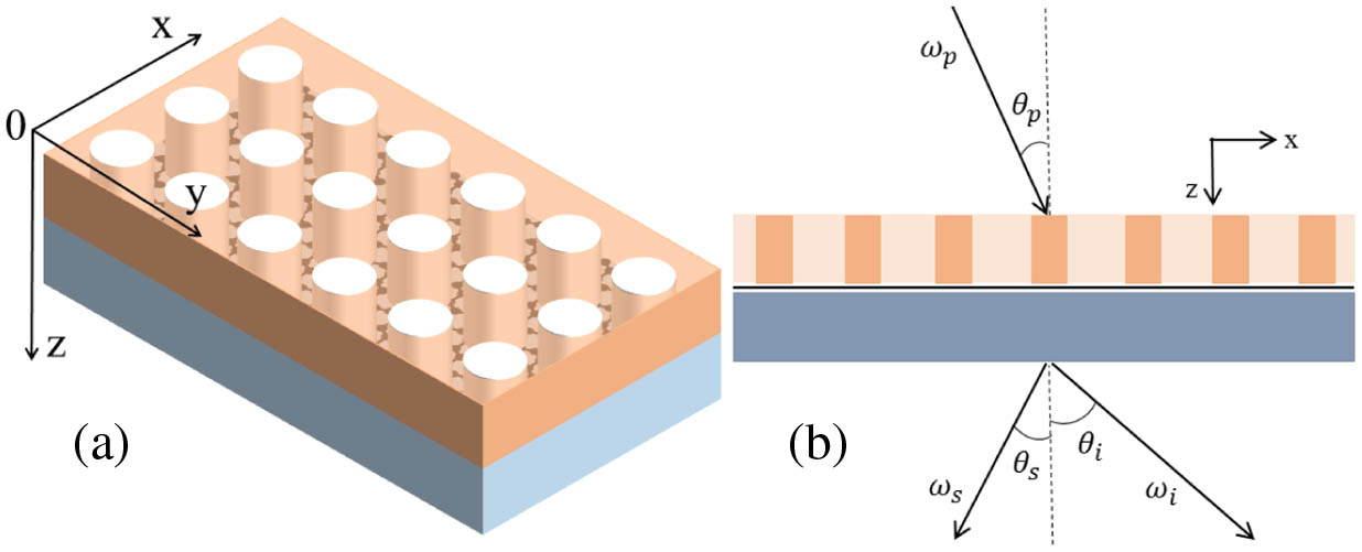
We consider a three-layer structure consisting of a photonic crystal slab, a monolayer , and a dielectric slab as shown in Figs. 1(a) and 1(b). The monolayer is put at the interface between the photonic crystal slab and the dielectric slab. The photonic crystal slab consists of a square lattice of air holes introduced into a high-index dielectric medium, and the corresponding lattice constant is denoted by . The thickness, relative permittivity, and relative permeability of this high-index medium are denoted by , , and , respectively. The thickness, relative permittivity, and relative permeability of the dielectric slab are represented by , , and , respectively. The thickness, relative permittivity, relative permeability, and second-order susceptibility of the monolayer are described by , , , and . All these materials are taken to be nonmagnetic. The photonic crystal slab and dielectric slab are taken to be linear in order to investigate the nonlinear effect of monolayer . As one component of TMDC monolayers, the relative permittivity of monolayers can be calculated by the permittivity of TMDC monolayer , which is equal to a superposition of Lorentzian functions [42,43], , where is the angular frequency of the EM wave; , , and represent the oscillator strength, resonance frequency, and spectral width of the th oscillator, respectively; and the values of these model parameters are provided in Ref. [44].
Figure 1.(a) Diagram of the photonic crystal slab-monolayer -slab. The air holes are arranged in a square lattice with lattice constant and the radius of the holes is . The thicknesses of the photonic crystal slab and dielectric slab are denoted by and , and the monolayer is put at the interface between the photonic crystal slab and the dielectric slab. (b) Schematic of the photon-pair generation process in the three-layer structure. The pump beam with frequency and angle is incident on the three-layer structure, and due to the second-order nonlinear effect of the monolayer , the signal field with frequency and angle and the idler field with frequency and angle are generated.
A. Theory for the Spontaneous Parametric Down-Conversion in the Photonic Crystal Slab-Monolayer WS2-Slab Structure
In contrast to the graphene, TMDC monolayers are noncentrosymmetric and therefore the second-order nonlinear effect is allowed. Based on the symmetry properties of their space group , it can be shown that the structure of their quadratical susceptibility tensor yields only one independent and nonvanishing component [4,5]: where represents the zigzag direction of the monolayer and is the orthogonal armchair direction. According to Ref. [23], the effective thickness of the monolayer is taken as . Figure 1(b) shows the process of photon-pair generation in the three-layer structure. When a pump field with the angular frequency is incident on the structure, the signal and idler fields with angular frequencies and , respectively, are generated simultaneously due to the second-order nonlinear effect of the monolayer , the incident angle of the pump wave is denoted by , and the irradiated angles of the signal and idler fields are taken as and . The nonlinear interaction in the three-layer structure is described by a Hamiltonian : where is the permittivity of air and represent the components of susceptibility tensor of the monolayer . Here , , and denote the direction ( or ), is the positive frequency electric field for the classical strong pump wave at the monolayer , and and denote the corresponding electric field operators for the generated photons with frequencies and . , , and denote the corresponding negative frequency electric fields, which are the conjugated terms of the positive frequency fields. H.c. stands for a Hermitian conjugated term.
The plane-wave expansion method is utilized to study the photon-pair generation [45]. Because of the periodicity of the three-layer structure, the pump field can be expanded in plane waves as where is the Bragg wave vector of the pump field in the plane, is the reduced wave vector that lies in the surface Brillouin zone, and represent the reciprocal lattice vector, the corresponding wave vector along the direction is denoted by , and the magnitude of the wave vector is marked by . stands for the refractive index of the monolayer for the pump field with frequency , and denotes the velocity of light in the air. and represent the amplitude for the downward and upward propagating parts of the pump field. The electric field operators with the frequency and polarization for the signal () and idler () fields in the monolayer can be also expanded in plane waves [46,11]: Here is the reduced Planck constant, denotes the area of the transverse profile of the beam, and and are the imaginary parts of and , respectively. and are the annihilation operators for the generated field in the monolayer , and the superscript 2 represents that the monolayer is located at the second layer; these operators can be written in the matrix forms and . In a similar way, the annihilation operators for the generated field up (down) the three-layer structure are denoted by and ( and ); these operators can also be written in the matrix forms and (, 4). These operators can be expressed as where the submatrices of scattering matrix [45,47] and submatrices of transfer matrix [48] can be obtained by the boundary conditions, and the superscripts 1, 2 in the transfer matrixes stand for the slices consisting of the photonic crystal slab and monolayer . Based on Eq. (8), the operator matrixes and in the monolayer can be expressed in terms of the operator matrixes and outside the structure as It can be easily verified that the following equation holds: Combining Eqs. (9) and (10), we find that parts of the matrices , , , and , which connect the creation operators in the to the creation operators outside the structure, are constructed by parts of the inverse scattering matrix .
In classical scattering problems, the transmission (), reflection (), and absorption () can be calculated by the scattering matrix in the following method. Assuming that the wave is incident on the system, the transmitted wave and reflected wave can be calculated by the scattering matrix as Based on the calculated SH fields in Eq. (11), the electric field intensities of the transmitted and reflected SH fields radiated from the three-layer structure can be calculated by Thus, the conversion efficiencies for the SHG fields can be obtained as And the transmission (reflection ) is defined as the ratio of the flux of the transmitted (reflected) wave to the flux of the incident wave and can be expressed as According to the energy conservation, the absorption is The transmission , reflection , and absorption can also be defined as the expressions of , , and in Eq. (14) except that the transmitted wave amplitude and reflected wave amplitude calculated by the scattering matrixes and are replaced by the corresponding wave amplitudes calculated by the inverse scattering matrixes and .
After getting the transmission (), reflection (), absorption (), and the scattering (inverse) matrixes, we can get the corresponding electric field () distribution in the three-layer structure. Here we omit the effect of the photon-pair generation on the electric field distribution, because the second-order nonlinear effect is so weak compared with the fundamental frequency field. In the next part of this work, we denote the electric field () at the and () at and . Inserting Eqs. (3) and (5) into Eq. (2), we can get the following expression by using the transverse Fourier transformation: From Eq. (15), the transverse wave vectors of the pump, signal, and idler fields satisfy the following relations:
B. Theory for the Generation of Correlated Photon Pairs Based on Bound States in the Continuum
The output state of signal and idler fields can be obtained by the Schrödinger equation with the assumption of the incident vacuum state ; furthermore, we expand it to the first order in nonlinear perturbation as Inserting Eqs. (3), (5), and (15) into Eq. (17), can be expressed as Here and in the following, we assume that and . From Eq. (18), the following relation is satisfied in this process of parametric down-conversion: We are interested only in the second term of and the first term, vacuum state , can be neglected. Substituting Eq. (9) into Eq. (18), we can express operators and in terms of operators and . Then the second term of can be divided into the following four parts: where with where represents the probability amplitude that a photon pair occurs signal-forward and idler-forward, corresponds to signal-forward and idler-backward, to signal-backward and idler-forward, and to signal-backward and idler-backward. Here, forward and backward mean that the waves propagate down and up, respectively; the superscripts , , , and represent the marks for four kinds of modes, respectively. We only consider the contribution of the special terms and of the operator matrixes and () to the probability amplitudes, because these terms correspond to the photons radiated from the three-layer structure without decay. Then (, ) can be expressed as with and where the period of nonlinear interaction goes from to . The expressions for the above physical quantities must be normalized by , which indicates that will be replaced by in the calculation.
After the output states are obtained, the generation rate of correlated photon pairs can be analyzed. Thus, we define a quantity that describes the number of photon pairs that have a signal photon at the frequency and its twin idler photon at the frequency in the mode as follows: where the density operators of photons and are defined as with Combining Eqs. (21) and (23), the quantity can be written as Then we introduce to describe the number of signal photons at the frequency in the mode ; it can be expressed in the following form: Sometimes, the energy spectrum of the signal field is easy to be measured from the experimental view and is determined by the following expression: Inserting Eq. (23) into Eqs. (30) and (31), and can be expressed as Based on Eqs. (32) and (33), the mean number of photon pairs and the energy spectrum of the signal field can be obtained easily by the numerical calculations.
3. RESULTS AND DISCUSSION
In this section, we present numerical results for the efficiency of the photon-pair generation from the three-layer structure. In the following calculations, we take silicon nitride as a component of the photonic crystal slab and ZnSe as the material of the dielectric slab; their relative permittivities are taken as and [49]. The second-order nonlinear susceptibility of the monolayer is chosen to be , which is compatible with the results in Ref. [50], and the second nonlinear effects of and ZnSe can be neglected. We choose as the two-dimensional material because of its large second nonlinear susceptibility [42].
Figures 2(a)–2(c) show the transmission (), reflection (), and absorption () for the three-layer structure as a function of the wavelength; Figures 2(d)–2(f) correspond to the transmission (), reflection (), and absorption () for the same structure, respectively. The parameters are assumed to be the following: , , , and , and the angle of the incident electromagnetic wave is taken as 0°.
Figure 2.(a), (b), and (c) show the transmission (), reflection (), and absorption (a) spectra for the three-layer structure as shown in Fig. 1, respectively. (d), (e) and (f) display the corresponding transmission (), reflection (), and absorption () spectra, respectively.
It is clearly seen that many sharp resonant peaks appear, which correspond to BICs. The spectra on the left do not coincide with those on the right. The phenomenon originates from the non-Hermitian characteristics of the structure due to the losses of absorption and radiation [4]. The energy conservation law is satisfied for the , , and , which are determined by the scattering matrix . The corresponding energy conservation law is also satisfied for , , and , which are obtained by the inverse scattering matrix . The , , and a vary between 0 and 1, but and may be greater than 1 and may be less than . This is because the inverse scattering matrix describes the electromagnetic field being radiated from the three-layer structure, whereas the scattering matrix represents the electromagnetic field being absorbed by the structure.
In the following, we study the effect of the BIC on the second-harmonic generation (SHG) and photon-pair generation from the designed three-layer structure. As shown in Figs. 2(c) and 2(f) by the arrows, we take one BIC determined by the scattering matrix, which is located at 1555.0222 nm, and another BIC determined by the inverse scattering matrix, which is located at 1499.254 nm.
Figures 3(a) and 3(b) display the corresponding SHG conversions as a function of the wavelength of the pump field in different frequency regions. For comparison, the corresponding SHG conversion from the freestanding monolayer is represented by dashed lines. The incident angle and intensity of the pump field are taken as 0° and . It is seen from Fig. 3(a) that resonant peaks of the downward and upward second-harmonic waves appear and are located at the wavelength , which corresponds to the wavelength of the BIC determined by the scattering matrix. The efficiency of SHG in the monolayer is enhanced by about 4 orders of magnitude. In contrast, in Fig. 3(b) we cannot observe the resonant peaks near the BIC determined by the inverse scattering matrix.
Figure 3.(a) and (b) describe the downward (black line) and upward (red line) SHG conversion from the three-layer structure as a function of the wavelength of the pump field in different regions, and the corresponding SHG conversions from the freestanding monolayer are shown by the corresponding dashed lines. (c) and (d) exhibit energy (black line), (red line), (green line), and (blue line) of the three-layer structure as a function of the wavelength of the signal field in different regions, the corresponding energy spectra of the freestanding monolayer are represented by the dashed lines, and the wavelength of the pump field is . The parameters are assumed as follows: , , , and .
In Figs. 3(c) and 3(d), we plot energy spectra for , , , and of the three-layer structure as a function of the wavelength of the signal field. The pump field with the intensity is incident perpendicularly to the structure (), and the angle of the signal field is taken as . In order to make sure the signal and idler fields are located at the resonant states simultaneously, the wavelength of the pump field is fixed at . For comparison, the corresponding energy spectra of the freestanding monolayer are also shown by the dashed lines. Because of the ultrathin thickness, the downward and upward SHG conversions from the freestanding monolayer are nearly equal, the energy spectra in four modes of the freestanding monolayer are also nearly equal, and thus the dashed lines almost coincide with each other.
From Fig. 3(c), we can see that there is no resonant peak when the signal field is located at the BIC determined by the scattering matrix. The resonant peaks of energy spectra appear at in Fig. 3(d), where the signal field is located at the BIC determined by the inverse scattering matrix. The corresponding wavelength of the idler field is , which is obtained from the energy conservation condition , and the radiated angle of the idler field is , which is determined by the phase-matching condition as shown in Eq. (11), so the idler field is also located at the BIC determined by the inverse scattering matrix. Comparing these results with those from the freestanding monolayer , the energies of the signal field from the three-layer structure are enhanced by about 4 orders of magnitude.
These phenomena are different from some previous studies on the enhancement of photon-pair generation in one-dimensional photonic crystal [12,13,18], which is determined by the scattering matrix . As can be seen from Eq. (9), the annihilation operators of the generated fields are closely related to , and thus the corresponding creation operators are connected by . In Fig. 2, it is shown that the photon-pair generation is enhanced in the parametric down-conversion if the signal and idler fields are located at the BIC determined by the inverse scattering matrix . This can be understood by the distributions of the electric field amplitude in the structure.
In Figs. 4(a) and 4(b), we plot the electric field enhancements (black line) and (red line) determined by the scattering matrix and inverse scattering matrix of the three-layer structure as a function of the wavelength. The strength of the incident electrical field is assumed as 1, and here we neglect the nonlinear effect on the field distribution. It is clearly observed at that a resonant peak appears for , while there is no resonant peak for , so at this location the SHG [Fig. 3(a)] is enhanced. It is also clearly seen at that the resonant peak appears for , while there is no resonant peak for , so at this location the efficiency of photon-pair generation [Fig. 3(d)] is improved. Because the scattering matrix is different from the inverse scattering matrix , the enhancements and play different roles in the two processes. The corresponding absorption spectra a () in the structure are also shown in Figs. 4(c) and 4(d) [Figs. 4(e) and 4(f)]. It is seen clearly in Figs. 4(c) and 4(f) that there is a resonant peak of absorption a (), which originates from the obvious resonant peak of the field (). These phenomena should be attributed to non-Hermitian behavior of the structure due to the losses of absorption and radiation.
Figure 4.(a) and (b) exhibit the electric field enhancements (black line) and (red line) determined by the scattering matrix and inverse scattering matrix of the three-layer structure as a function of the wavelength. (c) and (d) describe the absorption a of the three-layer structure as a function of the wavelength in different regions; the corresponding absorption a of the freestanding monolayer is shown by the corresponding red lines. (e) and (f) show the absorption of the three-layer structure as a function of the wavelength in different regions; the corresponding absorption of the freestanding monolayer is represented by the red lines.
In addition to high generation rate, the signals generated in such a way have narrowed relative line width due to the appearance of the BICs [29]. The relative line width can be described by in the signal spectrum; here is the center wavelength of the peak and represents the full width at half-maximum of the peak. For example, is 0.0181% in Fig. 3(a) and 0.0268% in Fig. 3(d), which is much smaller than the relative line width presented in Ref. [51].
So far, the discussions are only for the case with the incident angle 0° of the pump field. In fact, the above phenomena also depend on the angle of the pump field. Figure 5(b) displays the energy spectra of the three-layer structure as a function of at various radiated angle ; the intensity of the pump field and are taken, and the radiated angle is equal to according to the phase matching condition. The wavelength of the pump field is chosen to make sure the signal and idler fields are located at the BICs determined by the inverse scattering matrix simultaneously. For comparison, the corresponding energy spectra of the freestanding monolayer are provided by the dashed lines. It is clearly seen that the resonant peaks appear at various radiated angles and are redshifted with the increase of . The relative line widths of the resonant peaks at the three different angles are 0.02324%, 0.04288%, and 0.06858%, respectively.
Figure 5.(a) The absorption of the three-layer structure as a function of the wavelength at various incident angles; the black, red, and green lines are the spectra at the incident angles , 10°, and 15°, respectively. (b) The energy spectra of the three-layer structure as a function of the wavelength at various radiated angles of the signal field , 10°, and 15°; the corresponding energy spectra of the freestanding monolayer are denoted by the dashed lines. The wavelengths of the pump fields which are incident normally are taken as , 797.856 nm, and 820.341 nm for various , respectively; the other parameters are assumed as follows: , , , and .
This means that narrowed relative line width of the generated signal is observed again. In order to disclose the physical origin of the phenomena, in Fig. 5(a) we plot the corresponding absorption of the three-layer structure as a function of the wavelength . The resonant peaks in absorption spectra correspond to the resonant peaks of the energy . These show again that the photon-pair generation can be enhanced dramatically if the signal and idler fields are located at the BIC simultaneously. The narrowed relative line width of the generated signal can be understood from the narrowed relative line width of absorption .
The above phenomena not only depend on the incident angle of the pump field; they are also sensitive to the radiated angle of the signal field. Figure 6(b) describes the energy , , , and of the three-layer structure as a function of the radiated angle , the pump field is incident normally, and the wavelengths of the pump and signal fields are chosen at and corresponding to the maximum in Fig. 3(d). We find that the energy decreases dramatically with the increase of the radiated angle and also nearly arrives at the minimum at 1°; this means that the present structure can be used to generate photon pairs with outstanding directivity. Such a phenomenon also corresponds to the absorption of the three-layer structure as a function of the incident angle as shown in Fig. 6(a). This is because the BIC is very sensitive to the incident angle.
Figure 6.(a) The absorption of the three-layer structure as a function of the incident angle . (b) The energy spectra (black line), (red line with circle), (green line with triangle), and (blue line) of the three-layer structure as a function of the radiated angle of the signal field. The wavelength of the pump field, which is incident normally, is taken as , and the wavelengths of the signal and idler fields are fixed at , the other parameters are assumed as follows: , , , and .
In the following, we provide the calculated results of the energy as a function of the wavelength for different tunable variables of the system. Figure 7 displays these results. Figures 7(a)–7(c) correspond to the cases with various radii of the air hole and the thicknesses of the photonic crystal slab and dielectric slab, respectively. The wavelengths of the pump fields are also taken to make sure the signal and idler fields are located at the BICs determined by the inverse scattering matrix simultaneously. For comparison, the corresponding energy spectra of the freestanding monolayer are also represented by the dashed lines. The location of the energy peak is blueshifted with the increase of the radius as shown in Fig. 7(a) and redshifted with the increase of the thickness of the dielectric slab as shown in Fig. 7(c). The location of the energy peak is nearly unchanged after tuning the thickness of the photonic crystal slab as shown in Fig. 7(b). The peak value can be tuned by changing the parameters , , and , and the enhancement arrives at about 7 orders when the radius of the air hole is taken as .
Figure 7.(a), (b), and (c) The energy as a function of the wavelength of the signal field under normal incident pump field, the signal and idler fields are also radiated normally, and the corresponding spectra of the freestanding monolayer are described by the dashed lines. (a) Various radii of the air hole; the wavelengths of the pump fields are fixed at , 751.173 nm, 749.627 nm, and 748.271 nm when the radii are , , , and . The other parameters are taken as follows: and . (b) Various thicknesses of the photonic crystal slab; the wavelengths of the pump fields are fixed at , 749.627 nm, 749.694 nm, and 749.749 nm when the thicknesses are , , , and . The other parameters are taken as follows: and . (c) Various thicknesses of the dielectric slab; the wavelengths of the pump fields are fixed at , 749.627 nm, 754.555 nm, and 759.204 nm when the thicknesses are , , , and . The other parameters are taken as follows: and . (d) The energy for different polarizations of generated photons as a function of the azimuthal angle of the normal incident pump field; the signal and idler fields are also radiated normally and are polarized in the , , , directions. The parameters are assumed as follows: , , , and .
In addition, we would like to point out that the generation rate of correlated photon pairs also depends on the azimuthal angle. Here the azimuthal angle is defined as the angle between the electric field and the axis when the corresponding electromagnetic wave is incident or radiated normally. In the above calculations, the pump field is polarized along the direction; that is to say, the azimuthal angle is fixed at , and the polarizations of the signal and idler fields are chosen along the direction.
Figure 7(d) shows the energy for different polarizations of generated photons as a function of the azimuthal angle of the normal pump field, and the signal and idler fields are also radiated normally. A period modulation in the spectra with period 180° is observed clearly. As is increased from 0° to 360°, the polarization of the pump electric field is rotated anticlockwise from the direction back to the original direction, and when the azimuthal angle is taken at , the pump electric field is polarized along the direction. In such a case, the energies resulting from the second-order nonlinear polarization and are the minima, and those resulting from the second-order nonlinear polarization and are the maxima. Thus, the generation efficiencies of signal and idler fields with polarizations and reach the minima, and those with polarizations and reach the maxima. The corresponding phenomena can also be found for the case with the azimuthal angle . This means that we can also utilize this property to tune the generation rate of the correlated photon pairs in a large range by changing the azimuthal angle.
4. SUMMARY
In summary, we have designed the photonic crystal slab--slab structures to improve the generation rate of correlated photon pairs. In order to calculate the generation rate of correlated photon pairs in such structures, the rigorous quantum theory of spontaneous parametric down-conversion with the plane wave expansion method has been developed. The mean number of output photon pairs and the signal field energy spectra have been calculated. The BIC of radiation modes in the monolayer has been demonstrated. We have found that the generation efficiency of correlated photon pairs is greatly improved if the signal and idler fields are located at the BIC determined by the inverse scattering matrix of the structure. This is in contrast to the previous investigations on the enhancement of photon-pair generation in some nanostructures such as photonic crystals, which is determined by the scattering matrix. The effect of the structure parameters on the generation rate of correlated photon pairs has also been discussed. It is found that the generation rate of the correlated photon pair can be improved by 7 orders of magnitude in some designed structures. The generated quantum signals are sensitive to the wavelength and exhibit narrowed relative line width and directivity, which is very beneficial for the quantum information processing.
References
[1] D. Bouwmeester, A. Ekert, A. Zeilinger. The Physics of Quantum Information(2000).
[2] M. A. Nielsen, I. L. Chuang. Quantum Computation and Quantum Information(2000).
Tiecheng Wang, Zhixin Li, Xiangdong Zhang. Improved generation of correlated photon pairs from monolayer WS2 based on bound states in the continuum[J]. Photonics Research, 2019, 7(3): 341