• Photonics Research
  • Vol. 10, Issue 7, 1723 (2022)
Moshe Katzman1、2, Maayan Priel1、2, Inbar Shafir1、2、3, Saawan Kumar Bag1、2, Dvir Munk1、2, Naor Inbar4, Moshe Feldberg2, Tali Sharabani2, Leroy Dokhanian1、2, Matan Slook1、2, and Avi Zadok1、2、*
Author Affiliations
  • 1Faculty of Engineering, Bar-Ilan University, Ramat-Gan 5290002, Israel
  • 2Institute for Nano-Technology and Advanced Materials, Bar-Ilan University, Ramat-Gan 5290002, Israel
  • 3Soreq NRC, Yavne 81800, Israel
  • 4Tower Semiconductors, Migal Ha’Emek 2310502, Israel
  • show less
    DOI: 10.1364/PRJ.457340 Cite this Article Set citation alerts
    Moshe Katzman, Maayan Priel, Inbar Shafir, Saawan Kumar Bag, Dvir Munk, Naor Inbar, Moshe Feldberg, Tali Sharabani, Leroy Dokhanian, Matan Slook, Avi Zadok. Surface acoustic wave photonic filters with a single narrow radio-frequency passband in standard silicon on insulator[J]. Photonics Research, 2022, 10(7): 1723 Copy Citation Text show less
    (a) Schematic illustration of a SAW-photonic, discrete-time microwave filter device in SOI. An optical beam (red) from input fiber 1, modulated by microwave-frequency information, illuminates a grating of metallic stripes (yellow). Thermoelastic expansion and contraction of the grating elements lead to the launch of SAWs, which pass across a resonator waveguide layout. Generation of SAWs is the most effective when the grating period and modulation frequency match those of a surface acoustic mode. Continuous-wave light from input fiber 2 is coupled into the resonator waveguide. The propagating SAWs imprint a replica of the input information onto the guided optical wave in each of N parallel waveguide sections within the resonator layout, via photoelasticity. (The racetrack layout shown in the figure includes N=2 such sections.) Due to the slow acoustic velocities, long delays between replicas are accommodated on-chip. The input microwave frequency information is, thereby, converted from input 1 to the output port, via SAWs. The response of the device is that of a discrete-time, delay-and-sum MWP filter with N taps. (b) Top-view optical microscope image of a fabricated two-tap device (see Section 3). The grating period Λ, the spacing Δy between parallel sections of the resonator waveguide, and the transverse extent l of the grating elements and of the stimulated surface acoustic wavefront are noted on the image.
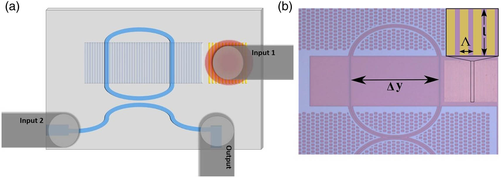
    Fig. 1. (a) Schematic illustration of a SAW-photonic, discrete-time microwave filter device in SOI. An optical beam (red) from input fiber 1, modulated by microwave-frequency information, illuminates a grating of metallic stripes (yellow). Thermoelastic expansion and contraction of the grating elements lead to the launch of SAWs, which pass across a resonator waveguide layout. Generation of SAWs is the most effective when the grating period and modulation frequency match those of a surface acoustic mode. Continuous-wave light from input fiber 2 is coupled into the resonator waveguide. The propagating SAWs imprint a replica of the input information onto the guided optical wave in each of N parallel waveguide sections within the resonator layout, via photoelasticity. (The racetrack layout shown in the figure includes N=2 such sections.) Due to the slow acoustic velocities, long delays between replicas are accommodated on-chip. The input microwave frequency information is, thereby, converted from input 1 to the output port, via SAWs. The response of the device is that of a discrete-time, delay-and-sum MWP filter with N taps. (b) Top-view optical microscope image of a fabricated two-tap device (see Section 3). The grating period Λ, the spacing Δy between parallel sections of the resonator waveguide, and the transverse extent l of the grating elements and of the stimulated surface acoustic wavefront are noted on the image.
    (a)–(c) Top-view optical microscope images of a 16-tap SAW-photonic MWP filter device. Scale bars correspond to 200 μm, 100 μm, and 50 μm in the three panels, respectively. A square grating of gold stripes is deposited to the right of a long resonator waveguide. The resonator layout consists of 16 straight sections that run parallel to the grating stripes. (d), (e) Top-view optical microscope images of a 32-tap SAW-photonic MWP filter device. Scale bars correspond to 400 μm and 100 μm, respectively. A grating coupler for optical input can be seen at the end of a bus waveguide in the lower left corner of panel (d). A two-tap device to the right of the metallic grating is seen in panel (e).
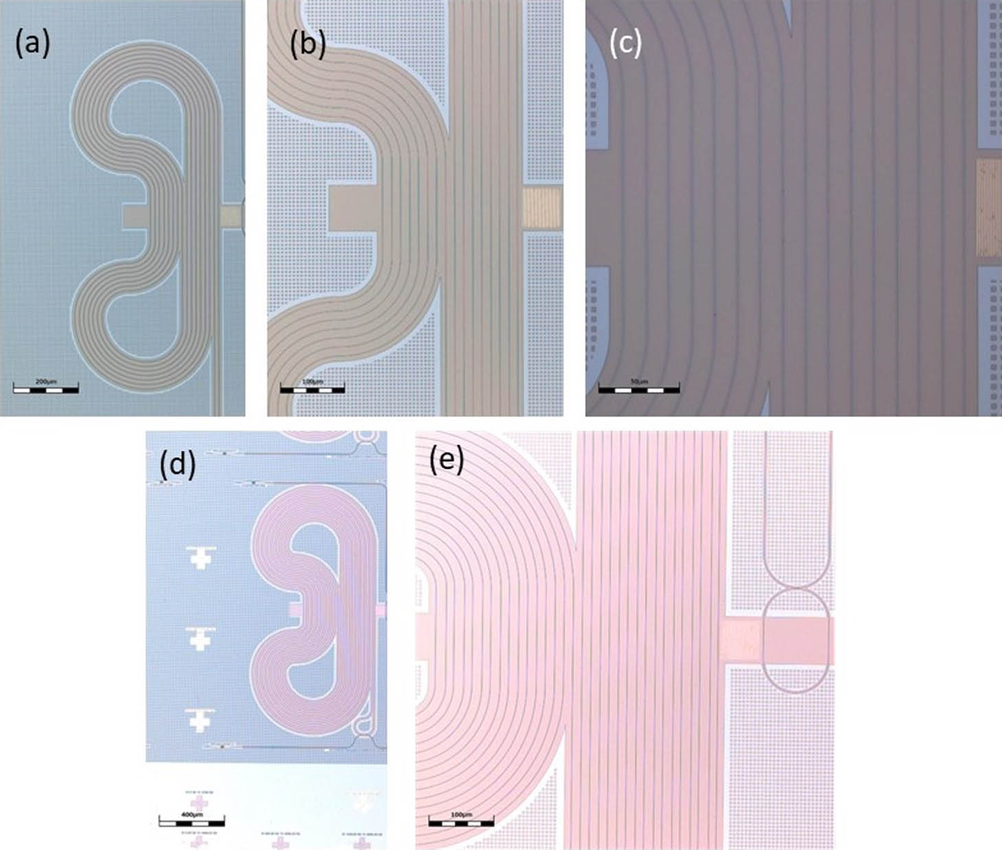
    Fig. 2. (a)–(c) Top-view optical microscope images of a 16-tap SAW-photonic MWP filter device. Scale bars correspond to 200 μm, 100 μm, and 50 μm in the three panels, respectively. A square grating of gold stripes is deposited to the right of a long resonator waveguide. The resonator layout consists of 16 straight sections that run parallel to the grating stripes. (d), (e) Top-view optical microscope images of a 32-tap SAW-photonic MWP filter device. Scale bars correspond to 400 μm and 100 μm, respectively. A grating coupler for optical input can be seen at the end of a bus waveguide in the lower left corner of panel (d). A two-tap device to the right of the metallic grating is seen in panel (e).
    (a) Measured normalized transfer function of optical power through the resonator waveguide of a 32-tap, SAW-photonic microwave filter device. The free spectral range of the transfer function is 55 pm, and its extinction ratio is 15 dB. (b) Experimental setup used in the measurement of MWP filter device transfer functions. EDFA, erbium-doped fiber amplifier; PC, polarization controller; EOM, electro-optic amplitude modulator; CW, continuous-wave. (c) Solid red, measured normalized transfer function |HTotal(Ω)|2 of radio-frequency electrical power through a two-tap SAW-photonic filter device. The metallic gratings consisted of M=43 periods, with Λ=1.4 μm. Periodic transmission with a free spectral range of 23 MHz is observed. The dotted black trace presents the normalized calculated transfer function |HR(Ω)|2 of a two-tap discrete-time filter with the same unit delay of the fabricated device. The periodic response is multiplied with a spectral envelope function |HG(Ω)|2 of thermoelastic SAWs stimulation (dashed red). The FWHM ΔΩG of the envelope bandwidth is 140 MHz. (d) Measured FWHM of thermoelastic SAWs actuation ΔΩG as a function of the number of periods M in the metallic grating. The width decreases with increasing grating size as anticipated.
    Fig. 3. (a) Measured normalized transfer function of optical power through the resonator waveguide of a 32-tap, SAW-photonic microwave filter device. The free spectral range of the transfer function is 55 pm, and its extinction ratio is 15 dB. (b) Experimental setup used in the measurement of MWP filter device transfer functions. EDFA, erbium-doped fiber amplifier; PC, polarization controller; EOM, electro-optic amplitude modulator; CW, continuous-wave. (c) Solid red, measured normalized transfer function |HTotal(Ω)|2 of radio-frequency electrical power through a two-tap SAW-photonic filter device. The metallic gratings consisted of M=43 periods, with Λ=1.4  μm. Periodic transmission with a free spectral range of 23 MHz is observed. The dotted black trace presents the normalized calculated transfer function |HR(Ω)|2 of a two-tap discrete-time filter with the same unit delay of the fabricated device. The periodic response is multiplied with a spectral envelope function |HG(Ω)|2 of thermoelastic SAWs stimulation (dashed red). The FWHM ΔΩG of the envelope bandwidth is 140 MHz. (d) Measured FWHM of thermoelastic SAWs actuation ΔΩG as a function of the number of periods M in the metallic grating. The width decreases with increasing grating size as anticipated.
    (a) Solid red, measured normalized transfer function |HTotal(Ω)|2 of radio-frequency electrical power through a 16-tap SAW-photonic filter device. The period Λ of the metallic grating elements was 1.32 μm. A single passband at 2.56 GHz frequency with an FWHM of 14 MHz is observed. The transmission of out-of-band components is suppressed by at least 15 dB. The dashed black trace presents the normalized calculated transfer function |HR(Ω)|2 of a 16-tap discrete-time filter with the same unit delay of the fabricated device. Additional passbands of the periodic transfer function fall outside the bandwidth of the normalized thermoelastic actuation response |HG(Ω)|2 of the chosen grating period [dashed red, measured using an adjacent two-tap device, similar to Fig. 3(c)]. Solid blue, measured |HTotal(Ω)|2 of a second 16-tap SAW-photonic filter device, with Λ=1.49 μm. The frequency response of thermoelastic actuation |HG(Ω)|2 for that choice of Λ is offset to lower frequency (dashed blue, measured using an adjacent two-tap device). The single passband is now obtained at 2.3 GHz. The transmission frequency matches a different peak of |HR(Ω)|2 (dashed black). (b) Solid red, measured |HTotal(Ω)|2 of a 32-tap SAW-photonic filter device, Λ=1.32 μm. The central transmission frequency is 2.56 GHz. The FWHM of the passband is 7 MHz, and out-of-band components are suppressed by at least 12 dB. Dashed black, calculated |HR(Ω)|2 of a 32-tap discrete-time filter with the same unit delay.
    Fig. 4. (a) Solid red, measured normalized transfer function |HTotal(Ω)|2 of radio-frequency electrical power through a 16-tap SAW-photonic filter device. The period Λ of the metallic grating elements was 1.32 μm. A single passband at 2.56 GHz frequency with an FWHM of 14 MHz is observed. The transmission of out-of-band components is suppressed by at least 15 dB. The dashed black trace presents the normalized calculated transfer function |HR(Ω)|2 of a 16-tap discrete-time filter with the same unit delay of the fabricated device. Additional passbands of the periodic transfer function fall outside the bandwidth of the normalized thermoelastic actuation response |HG(Ω)|2 of the chosen grating period [dashed red, measured using an adjacent two-tap device, similar to Fig. 3(c)]. Solid blue, measured |HTotal(Ω)|2 of a second 16-tap SAW-photonic filter device, with Λ=1.49  μm. The frequency response of thermoelastic actuation |HG(Ω)|2 for that choice of Λ is offset to lower frequency (dashed blue, measured using an adjacent two-tap device). The single passband is now obtained at 2.3 GHz. The transmission frequency matches a different peak of |HR(Ω)|2 (dashed black). (b) Solid red, measured |HTotal(Ω)|2 of a 32-tap SAW-photonic filter device, Λ=1.32  μm. The central transmission frequency is 2.56 GHz. The FWHM of the passband is 7 MHz, and out-of-band components are suppressed by at least 12 dB. Dashed black, calculated |HR(Ω)|2 of a 32-tap discrete-time filter with the same unit delay.
    Moshe Katzman, Maayan Priel, Inbar Shafir, Saawan Kumar Bag, Dvir Munk, Naor Inbar, Moshe Feldberg, Tali Sharabani, Leroy Dokhanian, Matan Slook, Avi Zadok. Surface acoustic wave photonic filters with a single narrow radio-frequency passband in standard silicon on insulator[J]. Photonics Research, 2022, 10(7): 1723
    Download Citation