• Photonics Research
  • Vol. 10, Issue 7, 1543 (2022)
Qun Hao1、2, Chuanxun Chen1, Jie Cao1、2, Zhikuo Li1, and Yang Cheng1、2、*
Author Affiliations
  • 1Key Laboratory of Biomimetic Robots and Systems, Ministry of Education, Beijing Institute of Technology, Beijing 100081, China
  • 2Yangtze Delta Region Academy of Beijing Institute of Technology, Jiaxing 314003, China
  • show less
    DOI: 10.1364/PRJ.455331 Cite this Article Set citation alerts
    Qun Hao, Chuanxun Chen, Jie Cao, Zhikuo Li, Yang Cheng. Ultra-wide varifocal imaging with selectable region of interest capacity using Alvarez lenses actuated by a dielectric elastomer[J]. Photonics Research, 2022, 10(7): 1543 Copy Citation Text show less
    (a) Architecture of the proposed lens elements. The proposed lens elements are mainly composed of a varifocal component and a scanning component. The two components are both driven by the DE actuators. The varifocal component is mainly composed of four acrylic frames, two lens elements of the Alvarez lenses, and two DE membranes. The lateral relative movements of the two lens elements can be realized by applying driving voltages to the right and left compliant electrodes on the DE membrane. Hence, the focal length of the varifocal component can be altered. The DE membrane of the scanning component is divided into four quadrants. The scanning component allows the varifocal component to move in different directions and makes the varifocal component images the region of interest in the center of the field of view by applying voltages on the DE-based four-quadrant actuators. (b) The photograph of the fabricated proposed lens elements with a selectable region of interest capacity using Alvarez lenses actuated by the DE membrane. The magnified picture is the fabricated Alvarez lenses viewed along the optical axis. (c) In the rest state (driving voltage is off), the two lens elements of the Alvarez lenses do not have lateral displacement, and the Alvarez lenses are equivalent to flat plates, i.e., parallel light enters and parallel light exits. (d) In the activation state (driving voltage is on), the focal length of the varifocal component is changed because the two lens elements move relative to each other when an actuation voltage is applied to the DE membrane. The exit light is focused by the varifocal component. (e) The three-dimensional view of the free-form surface of one lens element of the Alvarez lenses.
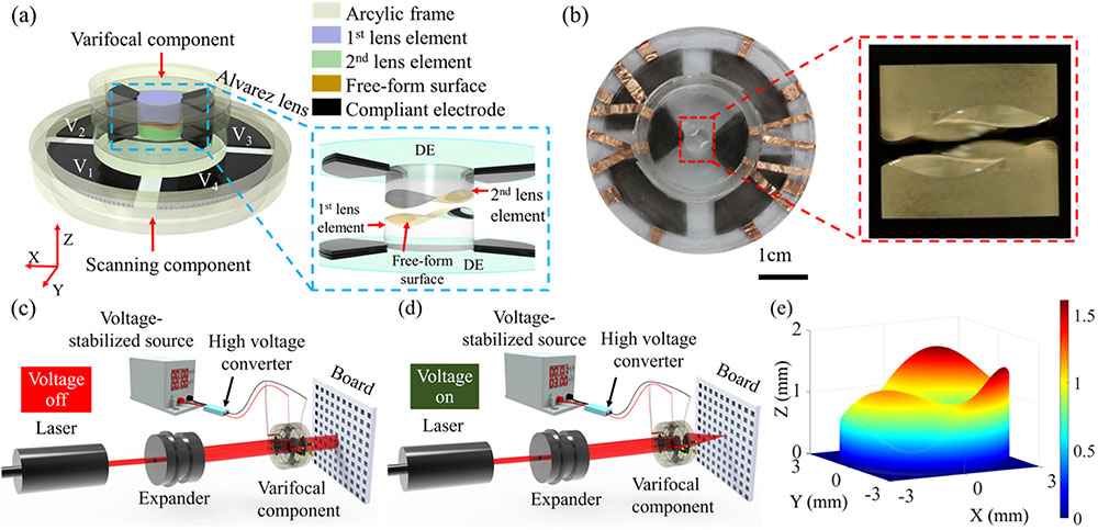
    Fig. 1. (a) Architecture of the proposed lens elements. The proposed lens elements are mainly composed of a varifocal component and a scanning component. The two components are both driven by the DE actuators. The varifocal component is mainly composed of four acrylic frames, two lens elements of the Alvarez lenses, and two DE membranes. The lateral relative movements of the two lens elements can be realized by applying driving voltages to the right and left compliant electrodes on the DE membrane. Hence, the focal length of the varifocal component can be altered. The DE membrane of the scanning component is divided into four quadrants. The scanning component allows the varifocal component to move in different directions and makes the varifocal component images the region of interest in the center of the field of view by applying voltages on the DE-based four-quadrant actuators. (b) The photograph of the fabricated proposed lens elements with a selectable region of interest capacity using Alvarez lenses actuated by the DE membrane. The magnified picture is the fabricated Alvarez lenses viewed along the optical axis. (c) In the rest state (driving voltage is off), the two lens elements of the Alvarez lenses do not have lateral displacement, and the Alvarez lenses are equivalent to flat plates, i.e., parallel light enters and parallel light exits. (d) In the activation state (driving voltage is on), the focal length of the varifocal component is changed because the two lens elements move relative to each other when an actuation voltage is applied to the DE membrane. The exit light is focused by the varifocal component. (e) The three-dimensional view of the free-form surface of one lens element of the Alvarez lenses.
    Schematic illustration of the fabrication procedure of the proposed lens elements. (a) The main components of the lower part of the varifocal component. The DE membrane (VHB4905, 3M Company) is pre-stretched with a ratio of 200%. The top and bottom sides of two local areas of the VHB4905 along the x-axis are coated with carbon powder (BP2000, Carbot) as compliant electrodes. (b) The assembled lower part of the varifocal component. (c) The upper part of the varifocal component is the same as the lower part, and it is rotated 180° to form the varifocal component together with the lower part. (d) The main components of the scanning component. The DE membrane (VHB4905, 3M Company) is also pre-stretched with a ratio of 200%. The stretched VHB4905 of the scanning component is divided into four quadrants. The four quadrants are coated with carbon powder (BP2000, Carbot) as compliant electrodes on both the top side and the bottom side. (e) The assembled scanning component. (f) The varifocal component is directly attached to the center of the DE membrane of the scanning component due to the inherent strong adhesion of the VHB4905. The whole dimension of the proposed lens elements is 24 mm×24 mm×9 mm (L×W×H).
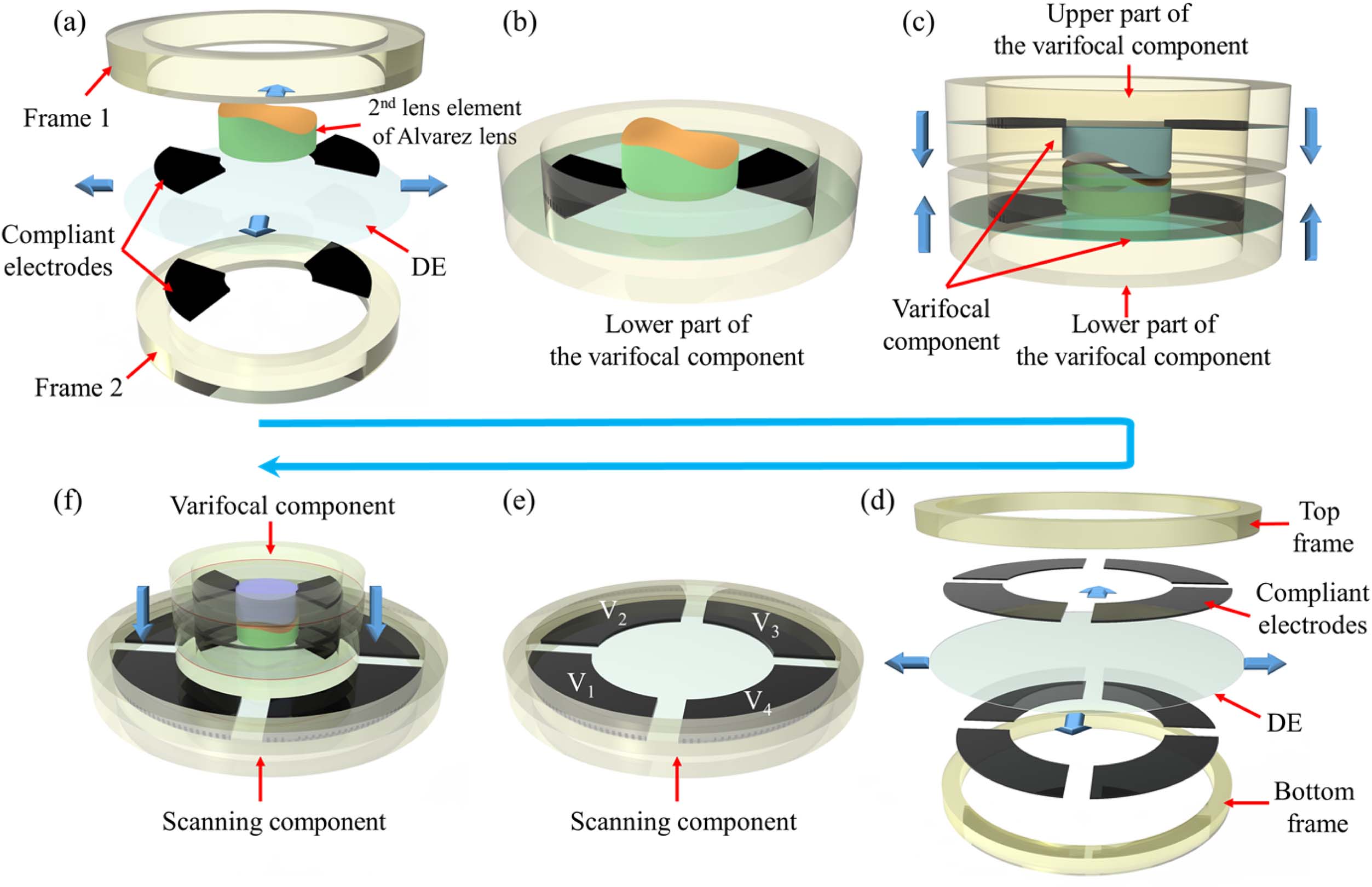
    Fig. 2. Schematic illustration of the fabrication procedure of the proposed lens elements. (a) The main components of the lower part of the varifocal component. The DE membrane (VHB4905, 3M Company) is pre-stretched with a ratio of 200%. The top and bottom sides of two local areas of the VHB4905 along the x-axis are coated with carbon powder (BP2000, Carbot) as compliant electrodes. (b) The assembled lower part of the varifocal component. (c) The upper part of the varifocal component is the same as the lower part, and it is rotated 180° to form the varifocal component together with the lower part. (d) The main components of the scanning component. The DE membrane (VHB4905, 3M Company) is also pre-stretched with a ratio of 200%. The stretched VHB4905 of the scanning component is divided into four quadrants. The four quadrants are coated with carbon powder (BP2000, Carbot) as compliant electrodes on both the top side and the bottom side. (e) The assembled scanning component. (f) The varifocal component is directly attached to the center of the DE membrane of the scanning component due to the inherent strong adhesion of the VHB4905. The whole dimension of the proposed lens elements is 24  mm×24  mm×9  mm (L×W×H).
    (a) Relationship between the lateral displacement of the lens element of the Alvarez lenses and the driving voltage applied to the active compliant electrode. (b) The experimental and theoretical focal lengths of the varifocal component. The experimental focal length is measured by the magnification method, and the theoretical focal length is evaluated by the lateral displacement according to Eq. (2).
    Fig. 3. (a) Relationship between the lateral displacement of the lens element of the Alvarez lenses and the driving voltage applied to the active compliant electrode. (b) The experimental and theoretical focal lengths of the varifocal component. The experimental focal length is measured by the magnification method, and the theoretical focal length is evaluated by the lateral displacement according to Eq. (2).
    (a) Demonstration of adaptive focusing by viewing three tissue sections placed at different distances from the proposed lens elements. Three tissue sections, including the daphnia (Tissue section 1), the fibrous connective (Tissue section 2), and the young embryo of Capsella bursa-pastos (Tissue section 3), are placed before the proposed lens elements with the distances of 3.0 mm, 4.5 mm, and 6.0 mm, respectively. (b) The experimental schematic to test the dynamic response time of the proposed varifocal component. (c) The recorded voltage of the photodetector when the input voltage is a square signal with the frequency of 1 Hz and an amplitude of 3.0 V. (d) The measured rise time and fall time of the proposed varifocal component. The rise and fall times are 160 ms and 295 ms, respectively.
    Fig. 4. (a) Demonstration of adaptive focusing by viewing three tissue sections placed at different distances from the proposed lens elements. Three tissue sections, including the daphnia (Tissue section 1), the fibrous connective (Tissue section 2), and the young embryo of Capsella bursa-pastos (Tissue section 3), are placed before the proposed lens elements with the distances of 3.0 mm, 4.5 mm, and 6.0 mm, respectively. (b) The experimental schematic to test the dynamic response time of the proposed varifocal component. (c) The recorded voltage of the photodetector when the input voltage is a square signal with the frequency of 1 Hz and an amplitude of 3.0 V. (d) The measured rise time and fall time of the proposed varifocal component. The rise and fall times are 160 ms and 295 ms, respectively.
    (a) Experimental schematic for evaluating the selectable region of interest capacity of the ultra-wide varifocal imaging system based on the proposed lens elements. By applying actuation voltage on the varifocal component using voltage-stabilized source 2 while applying actuation voltage on the scanning component using voltage-stabilized source 1, the varifocal component can magnify the object, and the scanning component allows the varifocal component to move in different directions, which endows the varifocal component with the capacity of making the selectable region of interest in the center of the field of view. (b) The experimental schematic for characterizing the image resolution of the ultra-wide varifocal imaging system. (c) The image at the rest state. There is no driving voltage applied to any quadrants of the scanning component and the varifocal component. (d)–(g) Images at different actuation states when different driving voltages are applied to the four-quadrant actuators of the scanning component. (h) The image of the resolution target at the rest state. There is no driving voltage applied to the varifocal component. (i)–(l) The images of the resolution target at different actuation states.
    Fig. 5. (a) Experimental schematic for evaluating the selectable region of interest capacity of the ultra-wide varifocal imaging system based on the proposed lens elements. By applying actuation voltage on the varifocal component using voltage-stabilized source 2 while applying actuation voltage on the scanning component using voltage-stabilized source 1, the varifocal component can magnify the object, and the scanning component allows the varifocal component to move in different directions, which endows the varifocal component with the capacity of making the selectable region of interest in the center of the field of view. (b) The experimental schematic for characterizing the image resolution of the ultra-wide varifocal imaging system. (c) The image at the rest state. There is no driving voltage applied to any quadrants of the scanning component and the varifocal component. (d)–(g) Images at different actuation states when different driving voltages are applied to the four-quadrant actuators of the scanning component. (h) The image of the resolution target at the rest state. There is no driving voltage applied to the varifocal component. (i)–(l) The images of the resolution target at different actuation states.
    Qun Hao, Chuanxun Chen, Jie Cao, Zhikuo Li, Yang Cheng. Ultra-wide varifocal imaging with selectable region of interest capacity using Alvarez lenses actuated by a dielectric elastomer[J]. Photonics Research, 2022, 10(7): 1543
    Download Citation