• Laser & Optoelectronics Progress
  • Vol. 57, Issue 10, 101103 (2020)
Jigang Wu*, Jun Shao, Gen Zhou, Deqiang Yang, and Yuan Cheng
Author Affiliations
  • Hunan Provincial Key Laboratory of Mechanical Equipment Health Maintenance, Hunan University of Science and Technology, Xiangtan, Hunan 411201, China
  • show less
    DOI: 10.3788/LOP57.101103 Cite this Article Set citation alerts
    Jigang Wu, Jun Shao, Gen Zhou, Deqiang Yang, Yuan Cheng. Vibration Measurement of Thin-walled Parts Based on Binocular Vision and Matching and Tracking of Features[J]. Laser & Optoelectronics Progress, 2020, 57(10): 101103 Copy Citation Text show less
    Binocular vision measurement model
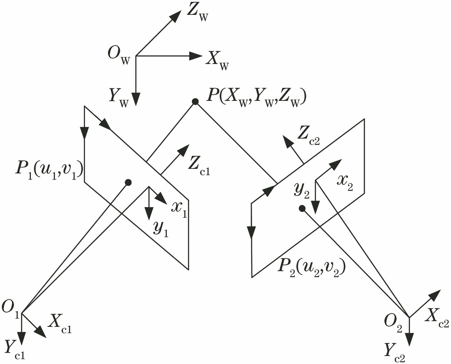
    Fig. 1. Binocular vision measurement model
    Schematic of feature point matching and tracking
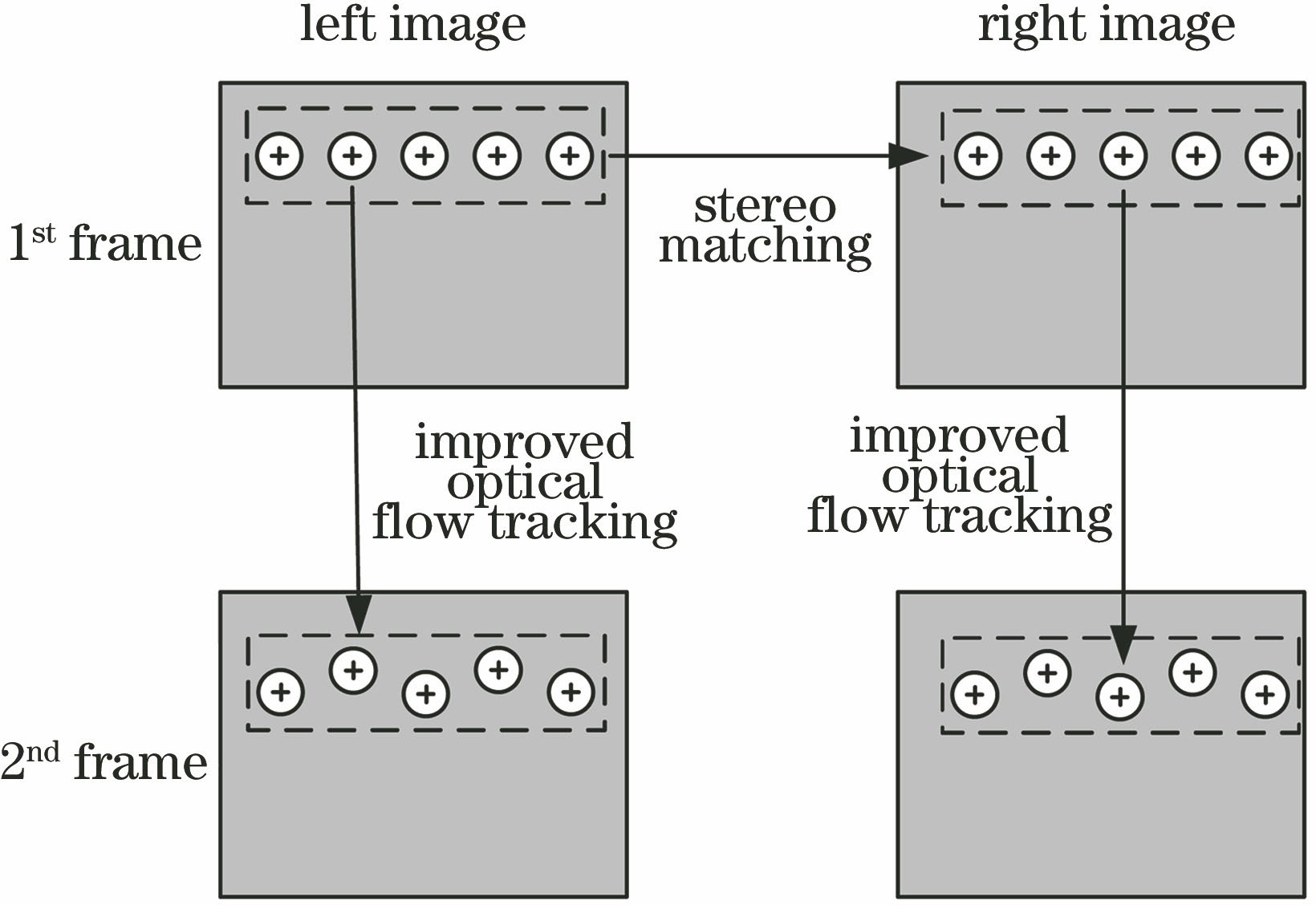
    Fig. 2. Schematic of feature point matching and tracking
    Flow chart of binocular vision vibration measurement
    Fig. 3. Flow chart of binocular vision vibration measurement
    Experiment system
    Fig. 4. Experiment system
    Image preprocessing. (a) Select region of interest; (b) preprocessed image
    Fig. 5. Image preprocessing. (a) Select region of interest; (b) preprocessed image
    Vibration displacement time history of 1# feature point in different directions. (a) X-axis displacement; (b) Y-axis displacement; (c) Z-axis displacement
    Fig. 6. Vibration displacement time history of 1# feature point in different directions. (a) X-axis displacement; (b) Y-axis displacement; (c) Z-axis displacement
    Y-axis displacement spectrum of 1# feature point
    Fig. 7. Y-axis displacement spectrum of 1# feature point
    Comparison of calculated displacement and theoretical vibration displacement of the proposed method. (a) X-axis displacement; (b) Y-axis displacement; (c) Z-axis displacement
    Fig. 8. Comparison of calculated displacement and theoretical vibration displacement of the proposed method. (a) X-axis displacement; (b) Y-axis displacement; (c) Z-axis displacement
    Each axial displacement error of 1# feature point
    Fig. 9. Each axial displacement error of 1# feature point
    Calibration parameterValue
    Left camera intrinsic matrix M11035.07901004.06101036.046560.578001
    Right camera intrinsic matrix M21028.8100995.88301029.363568.632001
    Left camera distortion matrix D1[-0.02679 0.06339 0.00112 0.00075 0]
    Right camera distortion matrix D2[-0.00092 0.02020 0.00207 -0.00089 0]
    Rotation structure matrix R1-0.00010.00120.00011-0.0042-0.00120.00421
    Translation structure matrix T[-17.7684 -0.3513 0.3255]T
    Table 1. Camera calibration results
    Jigang Wu, Jun Shao, Gen Zhou, Deqiang Yang, Yuan Cheng. Vibration Measurement of Thin-walled Parts Based on Binocular Vision and Matching and Tracking of Features[J]. Laser & Optoelectronics Progress, 2020, 57(10): 101103
    Download Citation