• Photonics Research
  • Vol. 10, Issue 2, 416 (2022)
Yibo Pan1、†, Feng Lan1、2、3、†,*, Yaxin Zhang1、2、4、*, Hongxin Zeng1, Luyang Wang1, Tianyang Song1, Guiju He1, and Ziqiang Yang1、2
Author Affiliations
  • 1School of Electronic Science and Engineering, University of Electronic Science and Technology of China, Chengdu 610054, China
  • 2Yangtze Delta Region Institute (Huzhou), University of Electronic Science and Technology of China, Huzhou 313001, China
  • 3e-mail: lanfeng@uestc.edu.cn
  • 4e-mail: zhangyaxin@uestc.edu.cn
  • show less
    DOI: 10.1364/PRJ.444773 Cite this Article Set citation alerts
    Yibo Pan, Feng Lan, Yaxin Zhang, Hongxin Zeng, Luyang Wang, Tianyang Song, Guiju He, Ziqiang Yang. Dual-band multifunctional coding metasurface with a mingled anisotropic aperture for polarized manipulation in full space[J]. Photonics Research, 2022, 10(2): 416 Copy Citation Text show less
    Schematics and working principles of the multifunctional integrated coding metasurface. (a) Trifunctional coding metasurfaces, F1, F2, and F3, denoting three independent functionalities; f1 and f2 represent the K- and Ka-bands, respectively. (b) Design and characterization of the proposed coding element.
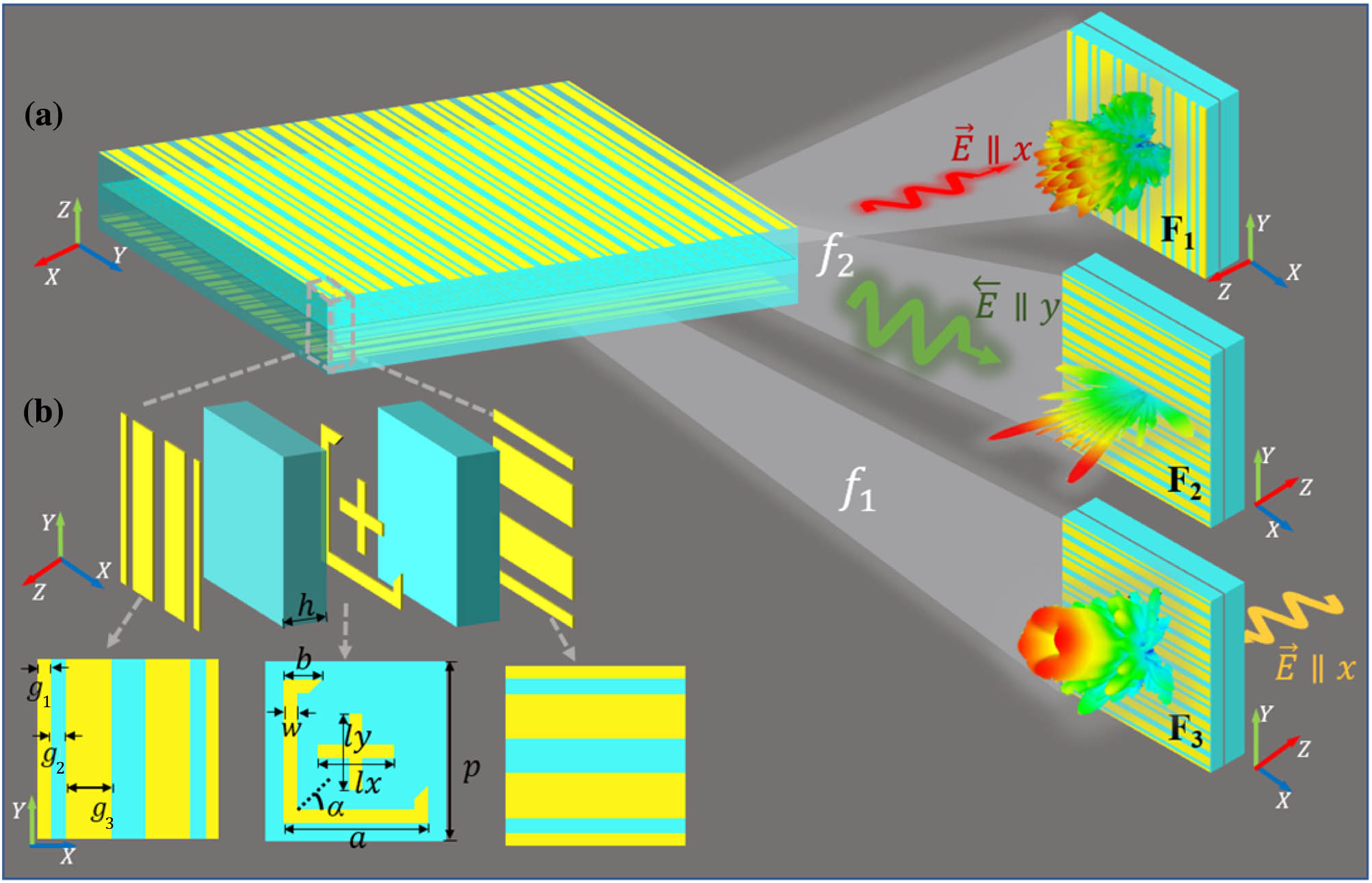
    Fig. 1. Schematics and working principles of the multifunctional integrated coding metasurface. (a) Trifunctional coding metasurfaces, F1, F2, and F3, denoting three independent functionalities; f1 and f2 represent the K- and Ka-bands, respectively. (b) Design and characterization of the proposed coding element.
    Schematic of Fabry–Perot resonance in transmission mode.
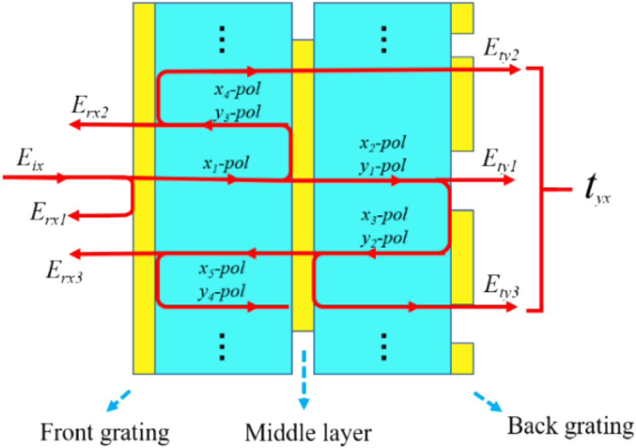
    Fig. 2. Schematic of Fabry–Perot resonance in transmission mode.
    Simulated surface current distributions of the middle layer. (a) Surface current intensity at 20 GHz under x-polarized incidence along the −z direction. (b) Surface current intensity at 39.9 GHz under x-polarized incidence along the −z direction. (c) Surface current intensity at 39.9 GHz under y-polarized incidence along the +z direction.
    Fig. 3. Simulated surface current distributions of the middle layer. (a) Surface current intensity at 20 GHz under x-polarized incidence along the z direction. (b) Surface current intensity at 39.9 GHz under x-polarized incidence along the z direction. (c) Surface current intensity at 39.9 GHz under y-polarized incidence along the +z direction.
    Reflection and transmission performance of the coding elements in Ka- and K-bands. (a), (b) Reflection phase and amplitude with different size parameters lx and ly in high frequency band. (c) Transmission phase and amplitude with varying parameters of size b and rotation angle α in low frequency band. (d) PCR of the coding metasurface under incidence of x- and y-polarization waves along z direction. (e) Specific dimensions and corresponding codes of the coding element.
    Fig. 4. Reflection and transmission performance of the coding elements in Ka- and K-bands. (a), (b) Reflection phase and amplitude with different size parameters lx and ly in high frequency band. (c) Transmission phase and amplitude with varying parameters of size b and rotation angle α in low frequency band. (d) PCR of the coding metasurface under incidence of x- and y-polarization waves along z direction. (e) Specific dimensions and corresponding codes of the coding element.
    Coding state cross-talk: (a) 3-bit-coding with reflection amplitude and phase variation under different values of lx and ly, when b is specified as 1.50 mm and α is fixed as 45°. (b) 1-bit coding with transmission amplitude and phase variation under different values of b and rotation angle α, when lx and ly are fixed as 1.7 mm.
    Fig. 5. Coding state cross-talk: (a) 3-bit-coding with reflection amplitude and phase variation under different values of lx and ly, when b is specified as 1.50 mm and α is fixed as 45°. (b) 1-bit coding with transmission amplitude and phase variation under different values of b and rotation angle α, when lx and ly are fixed as 1.7 mm.
    Phase distribution of designed coding sequences and corresponding integrated layout of the metasurface. Phase distribution of (a) RCS reduction, (b) beam splitting, and (c) vortex beam generation. (d), (e) Top view of top and middle layouts of the integrated trifunctional metasurface.
    Fig. 6. Phase distribution of designed coding sequences and corresponding integrated layout of the metasurface. Phase distribution of (a) RCS reduction, (b) beam splitting, and (c) vortex beam generation. (d), (e) Top view of top and middle layouts of the integrated trifunctional metasurface.
    Performance of proposed metasurface for x-polarized plane wave incidence at 39.9 GHz. (a), (b) Simulated 3D scattering pattern of the coding metasurface and the identical metallic reference plate. (c) Quantitative comparison of 2D RCS patterns of the metasurface and the metallic plate when φ is fixed as 0°. (d) Simulated coding metasurface and metallic plate RCS in the Ka-band and corresponding RCS reduction.
    Fig. 7. Performance of proposed metasurface for x-polarized plane wave incidence at 39.9 GHz. (a), (b) Simulated 3D scattering pattern of the coding metasurface and the identical metallic reference plate. (c) Quantitative comparison of 2D RCS patterns of the metasurface and the metallic plate when φ is fixed as 0°. (d) Simulated coding metasurface and metallic plate RCS in the Ka-band and corresponding RCS reduction.
    Simulated 3D and 2D results of beam splitting pattern at 39.9 GHz. (a) 3D far-field scattering pattern. (b) Normalized electric field scattering pattern.
    Fig. 8. Simulated 3D and 2D results of beam splitting pattern at 39.9 GHz. (a) 3D far-field scattering pattern. (b) Normalized electric field scattering pattern.
    Far-field and near-field results under x−LP plane wave incidence at 20 GHz. (a) 3D far-field radiation pattern. (b) Normalized intensity of the Ey component of the electric field on the x−y cutting plane. (c) Simulated near-field phase distribution with topological charge l=+2. (d) OAM spectra of the transmitted wave under x- and y-polarized wave incidences.
    Fig. 9. Far-field and near-field results under xLP plane wave incidence at 20 GHz. (a) 3D far-field radiation pattern. (b) Normalized intensity of the Ey component of the electric field on the xy cutting plane. (c) Simulated near-field phase distribution with topological charge l=+2. (d) OAM spectra of the transmitted wave under x- and y-polarized wave incidences.
    (a), (b) Experimental setups of far-field and near-field measurements in the anechoic chamber, respectively. (c) Comparison of measured and simulated results of bistatic RCS at 39.9 GHz. (d) Comparison of measured and simulated results of beam splitting at 39.9 GHz.
    Fig. 10. (a), (b) Experimental setups of far-field and near-field measurements in the anechoic chamber, respectively. (c) Comparison of measured and simulated results of bistatic RCS at 39.9 GHz. (d) Comparison of measured and simulated results of beam splitting at 39.9 GHz.
    Measured results of the near-field phase, intensity distribution, and mode spectra of OAM beams with mode l=+2 at (a) 16 GHz, (b) 19 GHz, and (c) 24 GHz. (d) Simulated and measured OAM mode purities with mode l=+2.
    Fig. 11. Measured results of the near-field phase, intensity distribution, and mode spectra of OAM beams with mode l=+2 at (a) 16 GHz, (b) 19 GHz, and (c) 24 GHz. (d) Simulated and measured OAM mode purities with mode l=+2.
    Yibo Pan, Feng Lan, Yaxin Zhang, Hongxin Zeng, Luyang Wang, Tianyang Song, Guiju He, Ziqiang Yang. Dual-band multifunctional coding metasurface with a mingled anisotropic aperture for polarized manipulation in full space[J]. Photonics Research, 2022, 10(2): 416
    Download Citation