
Yibo Pan, Feng Lan, Yaxin Zhang, Hongxin Zeng, Luyang Wang, Tianyang Song, Guiju He, Ziqiang Yang. Dual-band multifunctional coding metasurface with a mingled anisotropic aperture for polarized manipulation in full space[J]. Photonics Research, 2022, 10(2): 416
- Photonics Research
- Vol. 10, Issue 2, 416 (2022)
Abstract
1. INTRODUCTION
Metasurfaces, the two-dimensional (2D) version of artificial electromagnetic (EM) metamaterials [1,2], have attracted great interest due to their simple fabrication and powerful manipulation of EM waves. By introducing field discontinuities across an interface, metasurfaces enable precise EM wave control and local tailoring by altering their phases, amplitudes, and polarizations [3–6] on demand. After years of ongoing studies, various metasurfaces with gradient phase discontinuity have been proposed to manipulate wavefronts to implement multifarious applications, such as anomalous reflection [7,8] or refraction [9], focusing lenses [10,11], vortex beam generation [12–15], and polarization manipulation [16–18].
The concept of coding metasurfaces [19–23] was initially put forward by Cui
With the rapid development of modern integrated systems, 6G communication, imaging, and wireless sensor networks have increasingly higher demands for multitasking equipment [24]. Thus the single-function equipment [25–27] cannot meet system integration needs. Recently, anisotropic single-layer and multi-layer multifunctional metasurfaces have been reported to perform diverse functions through various flexible multiplexing techniques, including frequency, polarization, and direction multiplexing [7–9,28–31]. For frequency multiplexing metasurfaces, Cui
Sign up for Photonics Research TOC. Get the latest issue of Photonics Research delivered right to you!Sign up now
Herein, we present a tri-layer multifunctional coding metasurface that can efficiently implement 3-bit-coding vortex beam generation in K-band and 1-bit-coding beam splitting and radar cross-section (RCS) reduction in Ka-band. To enlarge bandwidth and information capacity, we stacked the split-ring and cross-shaped resonators horizontally into a functionally mingled aperture, begetting independently controlled polarization encoding in two widely separated frequency bands. In addition, the high polarization conversion rate and inter/intra-element coupling under transmission and reflection modes give birth to ultra-low interference of both cross-polarization states and frequency bands, which guarantee phase-shift linearity and precision. Further applying the coding sequences based on convolution theorem, Snell’s law, and vortex optics, the mingled aperture evolves into a dual-band, orthogonal-polarization, and full-space coding aperture for diversified multitasking implementations. Compared to other successful demonstrations, the proposed multifunctional meta-device opens a way to comprehensively manipulate a wavefront interface in extendable degrees of freedom. As a proof of concept, we experimentally demonstrate the trifunctional metasurface, including vortex beam generation, beam splitting, and RCS reduction. The experimental results indicate that the proposed metasurface can effectively realize diverse EM manipulations in full space, leading to many potential applications in different scenarios.
2. RESULTS AND DISCUSSION
A. Concept and Unit Cell Design
Figure 1(a) illustrates the conceptual diagram of the proposed coding metasurface. Depending on orthogonal polarization states and the directions of the incident wave, the meta-device works under both reflective and transmissive modes to independently perform different functions () in two-fold separated frequency bands. For the reflective operation mode, the downward and upward incoming plane waves with -polarized and -polarized components tune into diffuse scattering (function ) and anomalous deflection (function ) in the Ka-band (), respectively. For the symmetrically transmissive operation mode, the downward and upward incoming plane waves with -polarized and -polarized components can be transduced to a second-order vortex beam (function ) in the K-band (). The tri-layer meta-device comprises a shared coding aperture of split-ring and cross-shaped resonators inserted amid two layers of orthogonal wire gratings. A blown-up illustration of the coding component is given in Fig. 1(b). It is composed of three metallic layers with 0.035 mm thickness, separated by two identical F4B substrates (, ) with a thickness of . The orthogonal grating-wire layers are geometrically identical, allowing the orthogonal incident components to penetrate through or otherwise. A polarization-dependent coding matrix is applied on the shared aperture by implementing the variable-sized phase-shift scheme to integrate different functionalities of wavefront control. According to the aspect ratio between the outer split-ring and inner cross-shaped resonators, the combined scatterers with an enclosed manner achieve dual operation-frequency bands.
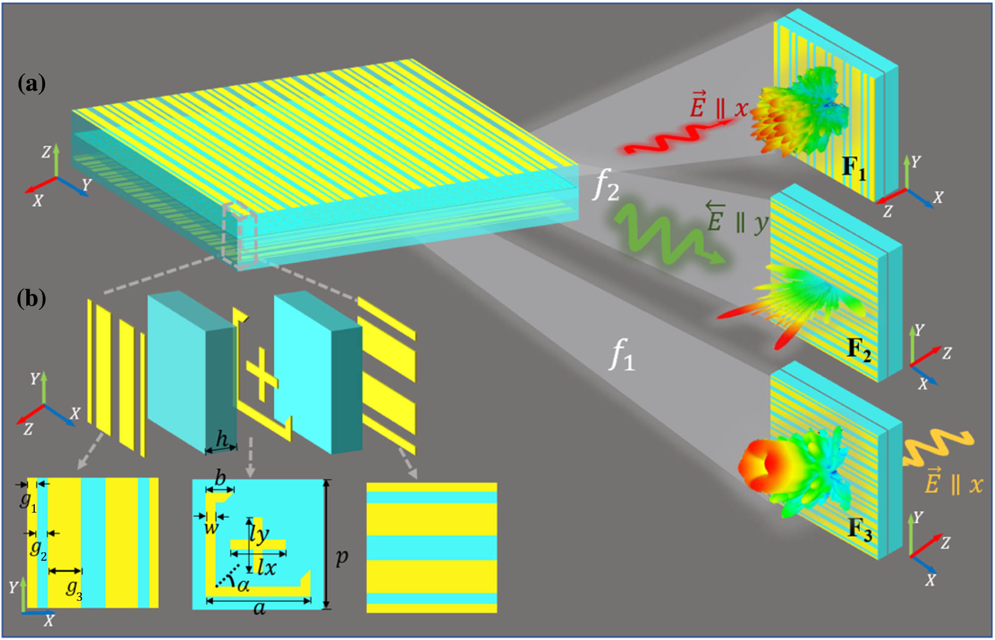
Figure 1.Schematics and working principles of the multifunctional integrated coding metasurface. (a) Trifunctional coding metasurfaces,
The detailed geometrical parameters are defined in Fig. 1(b). To simplify the design process, the basic element is designed with several fixed geometric parameters as follows: , , , , , , . With the open gap tilted 45° with respect to both and axes, the split-ring resonators symmetrically decompose the linearly polarized incidences into - and -polarized components. Moreover, in response to - or -polarized incident waves, the variable-sized phase-shift mechanism can be applied on both split-ring and cross-shaped structures by adjusting the corresponding dimensional parameters.
For the transmission mode, two layers of orthogonal wire gratings and the middle layer form a Fabry–Perot-like [37] cavity on the grounds of multiple interference theory. As shown in Fig. 2, the top and bottom grating layers serve as -polarized and -polarized selectors, and the middle layer acts as a polarization decomposer. Specifically, when an -polarized wave normally penetrates through the top orthogonal grating wires, the middle layer symmetrically decomposes the incident wave into cross-polarized and co-polarized components. Afterward, the transmitted waves, including both - and -polarized components, penetrate through the bottom grating layer, whereas the remaining - and -polarized components are reflected by the bottom layer and interact with the middle and top layers again. In the process, a small portion of the -polarized components reflected from the middle layer will pass through the top grating, whereas the reflected -polarized components will be blocked by the top gratings and then return to interact with the middle and bottom layers again. The above processes are repeated as multiple reflections and transmissions by matching the constructive and destructive interference requirements to cross-polarization and co-polarization, respectively. Eventually, the incident -polarized wave is near completely converted into the -polarized wave, resulting in high cross-polarization conversion efficiency over a broad operation frequency band. Based on Fabry–Perot resonant characteristics [38], expressed as , where the integer is the longitudinal mode coefficient, is the spacers’ dielectric refractive index, and is the cavity thickness, it resonates at about 23 GHz for this structure, which lies in the transmissive polarization conversion band.
![]()
Figure 2.Schematic of Fabry–Perot resonance in transmission mode.
Negligible cross talk among different polarization states and frequencies is an essential criterion for polarization and frequency multiplexing [7]. To specifically reveal the cross-talk performance, we use the CST Microwave Studio to investigate the surface current distributions. A unit-cell model with two Floquet ports set to the and directions and periodical boundaries set to and directions mimics the infinite array in the simulation. Figures 3(a) and 3(b) plot the simulated surface current distributions on a single meta-atom, both illuminated by the -polarized plane waves, at resonant frequencies of 20 GHz and 39.9 GHz, respectively. Noticeably, the strong current flowing occurs mainly on the two short arms of the split-ring resonator at 20 GHz but negligibly couples with the incidence at 39.9 GHz. On the contrary, the cross-shaped design resonates only at 39.9 GHz but hardly resonates at 20 GHz, indicating low-frequency cross talk between the split-ring structure and the cross-shaped structure, resulting in independent controls at both frequency bands. From Figs. 3(b) and 3(c), the two arms along and directions resonate only with the incident wave parallel to them and barely interact with each other. Also, due to the symmetrically polarized decomposition, the surface currents alongside the arms of the split-ring gap enable high-efficiency polarization conversion for the transmission modes. More evidence will come in the forthcoming section. In summary, the proposed structure has excellent isolation of orthogonal polarization and frequency, which is critical for the integration performance of the multifunctional metasurface.
![]()
Figure 3.Simulated surface current distributions of the middle layer. (a) Surface current intensity at 20 GHz under
Based on the above analysis, the polarization-dependent resonances at two operation bands are closely associated with their geometric parameters, denoted as , , and . By combining the split-ring and cross-shaped structures, the hybrid meta-atom can be used to control the transmitted wavefronts and the reflected wavefronts on both sides of the interface. To investigate the transmission and reflection characteristics of the proposed coding metasurface, we use the finite integration technique (FIT) in CST Microwave Studio to simulate and optimize the element, wherein the unit-cell boundaries are applied to and directions, and two Floquet ports are applied to and directions. First, we consider the reflection case for anomalous reflection and diffuse scattering. Four sets of parameters are selected by discretely adjusting and optimizing the geometric structure to achieve independent 1-bit phase manipulation for and linear polarization (LP) incidences along and directions in the high-frequency band. The length is optimized as 1.7 mm and 2.1 mm, which is the same as . The co-polarized reflective amplitude and phase of the coding element under and LP incidences in the high-frequency band are plotted in Figs. 4(a) and 4(b). The lengths for the four coding elements “0/0,” “0/1,” “1/0,” and “1/1” are optimized as 1.7 mm/1.7 mm, 1.7 mm/2.1 mm, 2.1 mm/1.7 mm, and 2.1 mm/2.1 mm, respectively. The two-digit number before and after the slash represents the coding phase sequence of the coding element under - and -LP incidences, respectively. It can be seen from the figure that the co-polarization reflection amplitude is higher than 0.9, and the phase difference between 0-unit and 1-unit is about 180° () from 37.5 GHz to 40 GHz when other parameters are fixed. Noting that the amplitude and phase response under -LP incidence is determined only by , where a change in the parameter barely affects it, and vice versa. The results above indicate very low coupling between orthogonal polarizations.
![]()
Figure 4.Reflection and transmission performance of the coding elements in Ka- and K-bands. (a), (b) Reflection phase and amplitude with different size parameters
Considering the case of transmission for vortex beam generation, a 3-bit coding implementation is carried out by variable-sized and 90° rotational phase-shift mechanisms to ensure polarization conversion efficiency and phase-shift linearity. By varying the size to achieve phase gradient and continuous phase wavefront, four lengths are optimized as 0.85 mm, 1.50 mm, 2.20 mm, and 2.85 mm. Due to the symmetric polarization decomposition, the progressive phase gradient can be expanded to a range by rotating the split-ring resonator to 90° around the axis [39]. Thereby an additional phase shift could be added to the progressive phase gradient through the variable-sized method while maintaining the consistency of the amplitude and phase shift in the corresponding frequency band. The relationship between an extra phase shift and the rotation angle can be expressed as . Therefore, the transmission phase progression of the eight coding elements nearly covers , corresponding to “000,” “001,” “010,” “011,” “100,” “101,” “110,” and “111” from 16 GHz to 24 GHz [see Fig. 4(c)], and the transmission amplitudes of the eight coding elements are above 0.9, with the phase-shift range reaching with a smooth phase gradient from 16 GHz to 24 GHz, when other parameters are fixed. According to the phased array theory, smooth phase shifts with near-unity amplitude favor high-efficiency beam control. The polarization conversion ratio (PCR) of the proposed metasurface for normal incidence is defined as [28] , where is the cross-polarization transmission coefficient, and is the co-polarization transmission coefficient. As shown in Fig. 4(d), almost all -polarized waves convert into -polarized waves, but the -polarized incident wave can hardly pass through the metasurface, indicating that the proposed metasurface can independently select an orthogonal polarization wave and realize high polarization conversion efficiency. Figure 4(e) presents the binary coding states with geometric parameters’ variations at two operating bands. One of the salient traits of the resonant structure is low interference between dual operation bands and orthogonal polarizations, leading to independent variable-sized coding states, as shown in the dark part of the inset figures.
The specific coupling level between the two operation bands is also shown in Figs. 5(a) and 5(b). By showing 1-bit-coding amplitudes and phase shifts under reflection mode and 3-bit-coding amplitudes and phase shifts under transmission mode, as depicted in Fig. 5(a), the transmission response under the -LP wave in the K-band is solely determined by and the rotation angle of the split-ring resonator, while changing and of the cross-shaped resonator has barely an effect on it. Figure 5(b) shows that changing the geometric parameters and the rotation angle of the split-ring resonator has almost no effect on the reflection response in the Ka-band. On the other hand, the consistency of the complex amplitude indicates a low cross-polarization level. Furthermore, by sandwiching the coding layer between the orthogonal wire-grating layers, the polarization-filtering effect allows penetration of normal -LP incidence along the direction to the transmission coding sequence while limiting -LP incidence from the direction to the reflection coding sequence and vice versa. In summary, the proposed building block has negligible frequency and orthogonal polarization cross talks, making it possible for full-space and dual-band wavefront control.
![]()
Figure 5.Coding state cross-talk: (a) 3-bit-coding with reflection amplitude and phase variation under different values of
B. Multifunctional Integrated Design
In real-world scenarios, one could implement multifunctional metasurfaces with anomalous reflection/transmission, diffuse scattering, focusing, and vortex beam generation through the 1-bit reflection or 3-bit transmission coding. It is worth noting that diverse beam shaping stems from functional coding sequences, avoiding interferences by degrees of freedom in terms of polarization, direction, frequency, etc. As a proof of concept, we employ the coding elements to synthesize a full-space tri-functional () metasurface with reflective RCS reduction, dual-beam deflection, and transmissive vortex beam generation under incident waves of different polarizations and directions. The metasurface contains elements with a total size of . For reflection cases F1 and F2, a convolutional RCS reduction coding arrangement and an anomalous reflection coding arrangement are under the illumination of -LP and -LP incident waves in the Ka-band toward and directions, respectively. As shown in Fig. 6(a), the coding sequence ends up with a convolution of the traditional orthogonal coding and cross coding through the addition theorem [40]. Figure 6(b) shows the gradient coding pattern , encoding a sequence “00011100011…” along the direction that can beget two main lobes with equal angles in space. Each dashed cell in Figs. 6(a) and 6(b) represents a super-cell, providing a stable EM response and reducing the reflection phase deterioration caused by the adjacent coupling. For the transmission case F3, the phase gradient is designed to generate a vortex beam with a topological charge of under the illumination of the -LP incident wave toward the direction. Within a circulation around the metasurface array, the adjacent regions keep phase intervals, as shown in Fig. 6(c). Figure 6(d) shows the top layer of the orthogonal wire gratings, where the bottom layer is geometrically identical but twists at an angle of 90°. By combining the coding-phase profiles shown in Figs. 6(a)–6(c), the corresponding array arrangement of the hybrid resonators turns out to be an anisotropic shared aperture, as shown in Fig. 6(e). Remarkably, the shared coding aperture delivers various wavefront manipulations by engineering its array factor within the frequency domain and spatial domain.
![]()
Figure 6.Phase distribution of designed coding sequences and corresponding integrated layout of the metasurface. Phase distribution of (a) RCS reduction, (b) beam splitting, and (c) vortex beam generation. (d), (e) Top view of top and middle layouts of the integrated trifunctional metasurface.
The integrated array models with open (add space) boundary conditions in all directions use the finite-difference time-domain (FDTD) technique in CST Microwave Studio to analyze near-field and far-field characteristics. Figure 7(a) shows the simulated 3D scattering pattern for the -LP plane wave incidence, impinging on the front side of the meta-device toward the direction. We can observe that the incident wave is randomly redirected to multiple directions in the upper half-space. To better compare the RCS reduction effect of the coding sequence, we simulated the comparison experiment of the same -LP incident wave incident on the same-sized metallic plate, as shown in Fig. 7(b). To compare numerically, we draw the 2D bistatic RCS pattern of the coding metasurface and the metallic plate on the plane at 39.9 GHz, where is the azimuthal angle of the plane. The quantitative comparison shows that about RCS reduction can be achieved in simulation, as shown in Fig. 7(c). Figure 7(d) compares the monostatic RCS reduction between the coding metasurface and the metallic plate under normal incidence from 37.5 GHz to 40 GHz. The result shows that the coding metasurface can effectively reduce the RCS in the Ka-band.
![]()
Figure 7.Performance of proposed metasurface for
The simulated 3D far-field beam splitting pattern is shown in Fig. 8(a). In the lower half-space, the normally incident wave is redirected into two symmetrical directions with a specific angle to the axis. In the case of normal incidence, the generalized Snell’s law can be expressed as [41]
![]()
Figure 8.Simulated 3D and 2D results of beam splitting pattern at 39.9 GHz. (a) 3D far-field scattering pattern. (b) Normalized electric field scattering pattern.
Vortex beams carrying orbital angular momentum (OAM) have captured great interest in the past few decades due to the inspiring application potential in optical and microwave fields. It has a spiral phase structure described by and can significantly expand communication capacity by coding optical communication information without increasing the bandwidth. The discrete phase distribution on the metasurface is mathematically written as [12]
![]()
Figure 9.Far-field and near-field results under
3. FABRICATION AND MEASUREMENT
To experimentally verify the performance of the proposed dual-band coding metasurface, we fabricated a metasurface sample with () elements by using the standard print circuit board (PCB). Precisely, the sample consists of two identical F4B substrate layers, and each layer is 1 mm thick with a relative permittivity of 2.65. The metal patterns are etched on both sides of the top and bottom substrate layers. The top view of the top and middle metallic layers is shown in the inset of Fig. 10(a). The measurement procedure is divided into two parts and is all carried out in a microwave anechoic chamber. Two LP Ka-band horn antennas are utilized as transmitter and receiver. The transmitter connects to a signal source (Keysight E8257D), and the receiver connects to a spectrum analyzer (Rohde & Schwarz). When rotated by 90°, the horn antennas can be switched between - and -LP waves. The sample and the transmitting horn antenna placed in front of it are fixed on the antenna turntable to keep the incident angle unchanged. Staying in the quasi-far-field zone of 1 m away from the transmitter, the sample is always under quasi-plane wave incidence when moving the antenna turntable. Due to the cable length limitation, the receiver horn antenna can receive the reflected wave only between and with 1° steps. Figure 10(c) compares the simulated and measured bistatic RCS results of coding pattern on the plane at 39.9 GHz. We observe about RCS reduction in the experiment compared with the same-sized metallic plate, which is close to the numerical simulation value. The measured 2D far-field pattern of coding pattern is depicted in Fig. 10(d). It can be seen that the incident quasi-plane wave beam is redirected to 18° and . The slight disagreement in the shapes of the main lobe and sidelobes is mainly due to the imperfect matching of the measurement environment and the fabrication errors. Overall, the measured results show good agreement with the numerical simulation, which proves our design’s feasibility.
![]()
Figure 10.(a), (b) Experimental setups of far-field and near-field measurements in the anechoic chamber, respectively. (c) Comparison of measured and simulated results of bistatic RCS at 39.9 GHz. (d) Comparison of measured and simulated results of beam splitting at 39.9 GHz.
Next, the near-field probing system presented in Fig. 10(b) is performed to measure the performance of vortex beam generation. Two ports of the vector network analyzer (Agilent N5230C) connect to the LP horn and probe. The LP horn antenna is 840 mm away from the fabricated sample to ensure quasi-plane wave incidence, and the measurement probe is placed 100 mm away from the sample to detect the amplitude and phase of the cross-polarization transmission wave. In the process of measurement, the probe is parallel to the axis to test the component of EM waves and moves along the and axes with a step length of 0.8 mm. Moreover, the scanning plane is parallel to the metasurface with an area of . The measured near-field energy intensity and phase distribution of the vortex beams at different frequencies are shown in Fig. 11. The helical phase distribution of variation and ring-shaped electric field intensity demonstrate that the coding metasurface could generate orbital vortex beams with the mode of , giving birth to a wide fractional bandwidth of 40% from 16 GHz to 24 GHz, which agrees well with the theoretical prediction. According to Eq. (3), we calculate the mode purity of the OAM beam with a particular order from the mode spectra of the simulation and measurement results. Defined as a ratio of the dominant mode power over the overall power distributed in all the modes, the mode purity [43] is expressed in Eq. (4):
![]()
Figure 11.Measured results of the near-field phase, intensity distribution, and mode spectra of OAM beams with mode
4. CONCLUSION
In summary, we have proposed and experimentally demonstrated a dual-band multifunctional coding metasurface that can control the transmitted and reflected wavefronts in full space by changing the frequency and direction of incident waves. By elaborately arranging specific coding sequences at corresponding frequencies, we have integrated three distinct functions on a shared aperture, including RCS reduction, beam splitting, and OAM generation. A satisfactory agreement between the results of simulation and measurement validates the excellent performance of the multifunctional metasurface. Attributed to its simplicity and efficiency, the proposed metasurface can be easily extended to other spectra, e.g., terahertz and optical bands, and implemented for multifunctional components, such as multiplexers, beam splitters, radomes, and focus lenses. Furthermore, the wavefront coding strategy of combining polarization, frequency, and direction with different functionalities dramatically expands the EM manipulation dimensions in a highly integrated and flexible manner, paving a path to reconfigurable intelligent surfaces for 6G communication systems.
References
[1] R. A. Shelby. Experimental verification of a negative index of refraction. Science, 292, 77-79(2001).
[2] J. B. Pendry. Controlling electromagnetic fields. Science, 312, 1780-1782(2006).
[3] N. Yu, F. Capasso. Flat optics with designer metasurfaces. Nat. Mater., 13, 139-150(2014).
[4] P. Xu, H. W. Tian, W. X. Jiang, Z. Z. Chen, T. Cao, C. Qiu, T. J. Cui. Phase and polarization modulations using radiation-type metasurfaces. Adv. Opt. Mater., 9, 2100159(2021).
[5] A. Arbabi, Y. Horie, M. Bagheri, A. Faraon. Dielectric metasurfaces for complete control of phase and polarization with subwavelength spatial resolution and high transmission. Nat. Nanotechnol., 10, 937-943(2015).
[6] Q. Wang, X. Zhang, Y. Xu, J. Gu, Y. Li, Z. Tian, R. Singh, S. Zhang, J. Han, W. Zhang. Broadband metasurface holograms: toward complete phase and amplitude engineering. Sci. Rep., 6, 32867(2016).
[7] X.-Y. Luo, W.-L. Guo, K. Qu, Q. Hu, K. Chen, H. Tang, J. Zhao, T. Jiang, Y. Feng. Quad-channel independent wavefront encoding with dual-band multitasking metasurface. Opt. Express, 29, 15678-15688(2021).
[8] G. D. Bai, Q. Ma, S. Iqbal, L. Bao, H. B. Jing, L. Zhang, H. T. Wu, R. Y. Wu, H. C. Zhang, C. Yang, T. J. Cui. Multitasking shared aperture enabled with multiband digital coding metasurface. Adv. Opt. Mater., 6, 1800657(2018).
[9] Y. Zhuang, G. Wang, T. Cai, Q. Zhang. Design of bifunctional metasurface based on independent control of transmission and reflection. Opt. Express, 26, 3594-3603(2018).
[10] X. Wan, X. Shen, Y. Luo, T. J. Cui. Planar bifunctional Luneburg-Fisheye lens made of an anisotropic metasurface: bi-functional Lunebur-Fisheye lens. Laser Photon. Rev., 8, 757-765(2014).
[11] F. Aieta, M. A. Kats, P. Genevet, F. Capasso. Multiwavelength achromatic metasurfaces by dispersive phase compensation. Science, 347, 1342-1345(2015).
[12] X. Gao, L. Tang, X. Wu, S. Li. Broadband and high-efficiency ultrathin Pancharatnam-Berry metasurfaces for generating X-band orbital angular momentum beam. J. Phys. D, 54, 075104(2021).
[13] F. Yue, D. Wen, C. Zhang, B. D. Gerardot, W. Wang, S. Zhang, X. Chen. Multichannel polarization-controllable superpositions of orbital angular momentum states. Adv. Mater., 29, 1603838(2017).
[14] L. Yang, S. Sun, W. E. I. Sha. Manipulation of orbital angular momentum spectrum using shape-tailored metasurfaces. Adv. Opt. Mater., 9, 2001711(2021).
[15] L.-J. Yang, S. Sun, W. E. I. Sha, Z. Huang, J. Hu. Arbitrary vortex beam synthesis with donut-shaped metasurface. IEEE Trans. Antennas Propagat..
[16] X. Gao, L. Singh, W. Yang, J. Zheng, H. Li, W. Zhang. Bandwidth broadening of a linear polarization converter by near-field metasurface coupling. Sci. Rep., 7, 6817(2017).
[17] R. T. Ako, W. S. L. Lee, S. Atakaramians, M. Bhaskaran, S. Sriram, W. Withayachumnankul. Ultra-wideband tri-layer transmissive linear polarization converter for terahertz waves. APL Photon., 5, 046101(2020).
[18] B. Han, S. Li, Z. Li, G. Huang, J. Tian, X. Cao. Asymmetric transmission for dual-circularly and linearly polarized waves based on a chiral metasurface. Opt. Express, 29, 19643-19654(2021).
[19] T. J. Cui, M. Q. Qi, X. Wan, J. Zhao, Q. Cheng. Coding metamaterials, digital metamaterials and programmable metamaterials. Light Sci. Appl., 3, e218(2014).
[20] K. Chen, L. Cui, Y. Feng, J. Zhao, T. Jiang, B. Zhu. Coding metasurface for broadband microwave scattering reduction with optical transparency. Opt. Express, 25, 5571-5579(2017).
[21] L. Li, T. J. Cui, W. Ji, S. Liu, J. Ding, X. Wan, Y. Bo Li, M. Jiang, C.-W. Qiu, S. Zhang. Electromagnetic reprogrammable coding-metasurface holograms. Nat. Commun., 8, 197(2017).
[22] Y. B. Li, L. L. Li, B. B. Xu, W. Wu, R. Y. Wu, X. Wan, Q. Cheng, T. J. Cui. Transmission-type 2-bit programmable metasurface for single-sensor and single-frequency microwave imaging. Sci. Rep., 6, 23731(2016).
[23] X. Wan, M. Q. Qi, T. Y. Chen, T. J. Cui. Field-programmable beam reconfiguring based on digitally-controlled coding metasurface. Sci. Rep., 6, 20663(2016).
[24] S. Gupta, Z. Briqech, A. R. Sebak, T. A. Denidni. Mutual-coupling reduction using metasurface corrugations for 28 GHz MIMO applications. IEEE Antennas Wireless Propag. Lett., 16, 2763-2766(2017).
[25] L. Wang, F. Lan, Y. Zhang, S. Liang, W. Liu, Z. Yang, L. Meng, Z. Shi, J. Yin, T. Song, H. Zeng, P. Mazumder. A fractional phase-coding strategy for terahertz beam patterning on digital metasurfaces. Opt. Express, 28, 6395-6407(2020).
[26] H. Zeng, Y. Zhang, F. Lan, S. Liang, L. Wang, T. Song, T. Zhang, Z. Shi, Z. Yang, X. Kang, X. Zhang, P. Mazumder, D. M. Mittleman. Terahertz dual-polarization beam splitter via an anisotropic matrix metasurface. IEEE Trans. Terahertz Sci. Technol., 9, 491-497(2019).
[27] H. Zeng, F. Lan, Y. Zhang, S. Liang, L. Wang, J. Yin, T. Song, L. Wang, T. Zhang, Z. Shi, Z. Yang, P. Mazumder. Broadband terahertz reconfigurable metasurface based on 1-bit asymmetric coding metamaterial. Opt. Commun., 458, 124770(2020).
[28] J. Fan, Y. Cheng. Broadband high-efficiency cross-polarization conversion and multifunctional wavefront manipulation based on chiral structure metasurface for terahertz wave. J. Phys. D, 53, 025109(2020).
[29] J. Yang, X. Wu, J. Song, C. Huang, Y. Huang, X. Luo. Cascaded metasurface for simultaneous control of transmission and reflection. Opt. Express, 27, 9061-9070(2019).
[30] L. Zhang, R. Y. Wu, G. D. Bai, H. T. Wu, Q. Ma, X. Q. Chen, T. J. Cui. Transmission-reflection-integrated multifunctional coding metasurface for full-space controls of electromagnetic waves. Adv. Funct. Mater., 28, 1802205(2018).
[31] W. Pan, T. Cai, S. Tang, L. Zhou, J. Dong. Trifunctional metasurfaces: concept and characterizations. Opt. Express, 26, 17447-17457(2018).
[32] Q. Wang, E. T. F. Rogers, B. Gholipour, C.-M. Wang, G. Yuan, J. Teng, N. I. Zheludev. Optically reconfigurable metasurfaces and photonic devices based on phase change materials. Nat. Photonics, 10, 60-65(2016).
[33] A. M. Shaltout, V. M. Shalaev, M. L. Brongersma. Spatiotemporal light control with active metasurfaces. Science, 364, eaat3100(2019).
[34] C. Huang, C. Zhang, J. Yang, B. Sun, B. Zhao, X. Luo. Reconfigurable metasurface for multifunctional control of electromagnetic waves. Adv. Opt. Mater., 5, 1700485(2017).
[35] K. Chen, Y. Feng, F. Monticone, J. Zhao, B. Zhu, T. Jiang, L. Zhang, Y. Kim, X. Ding, S. Zhang, A. Alù, C. Qiu. A reconfigurable active Huygens’ metalens. Adv. Mater., 29, 1606422(2017).
[36] S. J. Li, Y. B. Li, L. Zhang, Z. J. Luo, B. W. Han, R. Q. Li, X. Y. Cao, Q. Cheng, T. J. Cui. Programmable controls to scattering properties of a radiation array. Laser Photon. Rev., 15, 2000449(2021).
[37] H.-B. Wang, X. Zhou, D.-F. Tang, J.-F. Dong. Diode-like broadband asymmetric transmission of linearly polarized waves based on Fabry–Perot-like resonators. J. Mod. Opt., 64, 750-759(2017).
[38] H. Chen, H. Ma, J. Wang, S. Qu, Y. Pang, M. Yan, Y. Li. Ultra-wideband transparent 90° polarization conversion metasurfaces. Appl. Phys. A, 122, 463(2016).
[39] X. Zhang, Z. Tian, W. Yue, J. Gu, S. Zhang, J. Han, W. Zhang. Broadband terahertz wave deflection based on c-shape complex metamaterials with phase discontinuities. Adv. Mater., 25, 4567-4572(2013).
[40] R. Y. Wu, C. B. Shi, S. Liu, W. Wu, T. J. Cui. Addition theorem for digital coding metamaterials. Adv. Opt. Mater., 6, 1701236(2018).
[41] N. Yu, P. Genevet, M. A. Kats, F. Aieta, J.-P. Tetienne, F. Capasso, Z. Gaburro. Light propagation with phase discontinuities: generalized laws of reflection and refraction. Science, 334, 333-337(2011).
[42] S. Jiang, C. Chen, H. Zhang, W. Chen. Achromatic electromagnetic metasurface for generating a vortex wave with orbital angular momentum (OAM). Opt. Express, 26, 6466-6477(2018).
[43] F. Bi, Z. Ba, X. Wang. Metasurface-based broadband orbital angular momentum generator in millimeter wave region. Opt. Express, 26, 25693-25705(2018).

Set citation alerts for the article
Please enter your email address
© Copyright 2018-2021 | Chinese Laser Press. All Rights Reserved 沪ICP备15018463号-20