• Acta Optica Sinica
  • Vol. 39, Issue 6, 0623002 (2019)
Ling Wu1、*, Niannian Chen1, Yong Fan1, and Yidong Ye2
Author Affiliations
  • 1 School of Computer Science and Technology, Southwest University of Science and Technology, Mianyang, Sichuan 621010, China
  • 2 Institute of Applied Electronics, Chinese Academy of Engineering Physics, Mianyang, Sichuan 621900, China
  • show less
    DOI: 10.3788/AOS201939.0623002 Cite this Article Set citation alerts
    Ling Wu, Niannian Chen, Yong Fan, Yidong Ye. Surface Reconstruction of Large Aperture Plane Optical Components Based on Method of Relative Angle Difference[J]. Acta Optica Sinica, 2019, 39(6): 0623002 Copy Citation Text show less
    Principle of topography measurement system with relative angle difference. (a) Top view of measurement system; (b) diagram of catwalk measurement
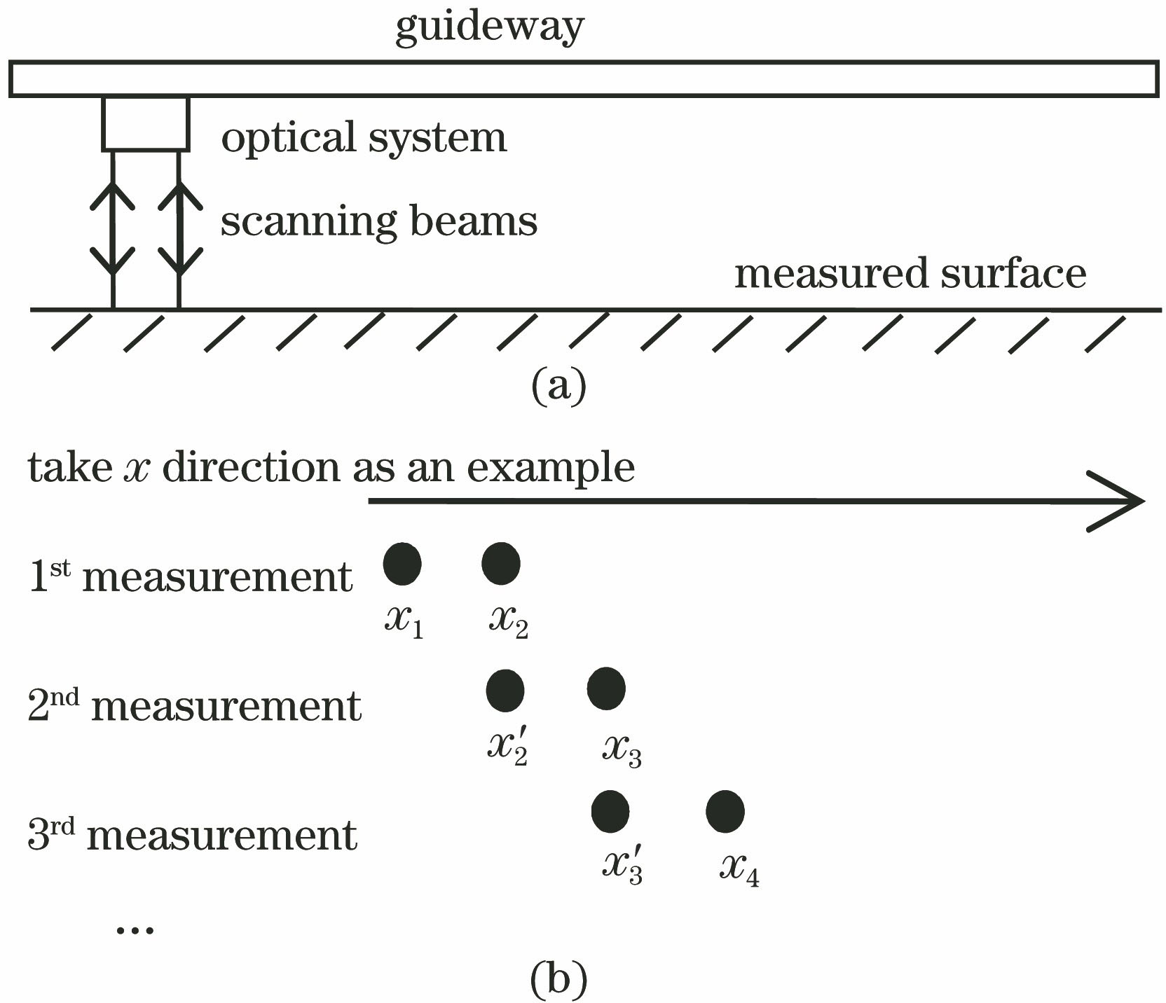
    Fig. 1. Principle of topography measurement system with relative angle difference. (a) Top view of measurement system; (b) diagram of catwalk measurement
    Laser spot array obtained by CCD
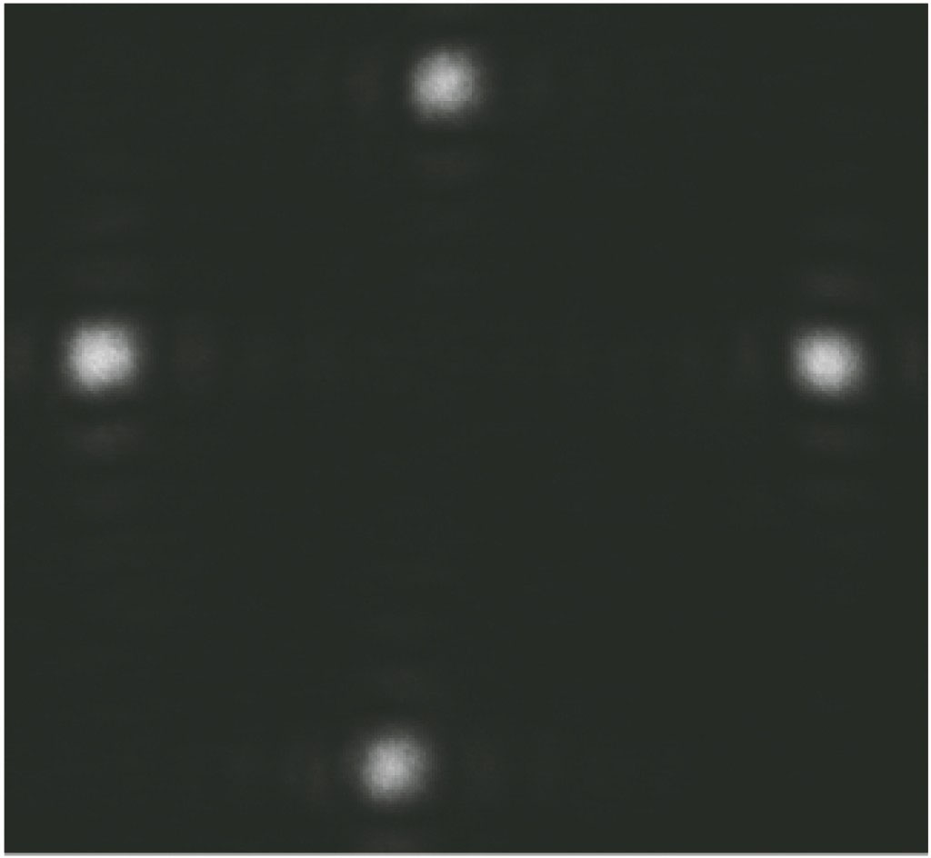
    Fig. 2. Laser spot array obtained by CCD
    Schematic for scanning process on measured surface
    Fig. 3. Schematic for scanning process on measured surface
    Reconstruction results with Gaussian noise (σ=0.2″). (a) Simulated surface to be tested; (b) reconstruction with CuRe method; (c) reconstruction with Zernike wavefront
    Fig. 4. Reconstruction results with Gaussian noise (σ=0.2″). (a) Simulated surface to be tested; (b) reconstruction with CuRe method; (c) reconstruction with Zernike wavefront
    Two different curved surfaces for simulation. (a) Z1; (b) Z2
    Fig. 5. Two different curved surfaces for simulation. (a) Z1; (b) Z2
    Comparison of reconstructed surface Z1 and residual errors with Gaussian noise (σ=0.2″). (a) Reconstruction result with proposed method; (b) reconstruction result with Zernike wavefront method; (c) reconstruction result with SLI method; (d) reconstructed residual error of proposed method; (e) reconstructed residual error of Zernike wavefront method; (f) reconstructed residual error of SLI method
    Fig. 6. Comparison of reconstructed surface Z1 and residual errors with Gaussian noise (σ=0.2″). (a) Reconstruction result with proposed method; (b) reconstruction result with Zernike wavefront method; (c) reconstruction result with SLI method; (d) reconstructed residual error of proposed method; (e) reconstructed residual error of Zernike wavefront method; (f) reconstructed residual error of SLI method
    Comparison of reconstructed surface Z2 and residual errors with Gaussian noise (σ=0.2″). (a) Reconstruction result with proposed method; (b) reconstruction result with Zernike wavefront method; (c) reconstruction result with SLI method; (d) residual error of proposed method; (e) residual error of Zernike wavefront method; (f) residual error of SLI method
    Fig. 7. Comparison of reconstructed surface Z2 and residual errors with Gaussian noise (σ=0.2″). (a) Reconstruction result with proposed method; (b) reconstruction result with Zernike wavefront method; (c) reconstruction result with SLI method; (d) residual error of proposed method; (e) residual error of Zernike wavefront method; (f) residual error of SLI method
    Reconstruction error statistics at different noise levels (σ=0-1 μrad). (a) 200 mm×200 mm, 17×17 sampling points; (b) 200 mm×200 mm, 34×34 sampling points; (c) 400 mm×400 mm, 34×34 sampling points
    Fig. 8. Reconstruction error statistics at different noise levels (σ=0-1 μrad). (a) 200 mm×200 mm, 17×17 sampling points; (b) 200 mm×200 mm, 34×34 sampling points; (c) 400 mm×400 mm, 34×34 sampling points
    Four repeated test results for small aperture optical component. (a) Topography measured by interferometer; (b)-(e) reconstruction results of proposed method; (f)-(i) reconstruction results with Zernike wavefront method
    Fig. 9. Four repeated test results for small aperture optical component. (a) Topography measured by interferometer; (b)-(e) reconstruction results of proposed method; (f)-(i) reconstruction results with Zernike wavefront method
    Two repeated test results for large aperture optical component. (a)(d) Topographies measured by interferometer; (b)(e) reconstruction results of proposed method; (c)(f) reconstruction results with Zernike wavefront method
    Fig. 10. Two repeated test results for large aperture optical component. (a)(d) Topographies measured by interferometer; (b)(e) reconstruction results of proposed method; (c)(f) reconstruction results with Zernike wavefront method
    Comparison of corresponding rows between reconstruction results of proposed method and topographies measured by interferometer. (a) y=75 mm; (b) y=175 mm
    Fig. 11. Comparison of corresponding rows between reconstruction results of proposed method and topographies measured by interferometer. (a) y=75 mm; (b) y=175 mm
    AlgorithmSmall aperture mirror (RMSE) /μmLarge aperture mirror (RMSE) /μm
    Test 1Test 2Test 3Test 4Test 1Test 2
    Zernike wavefront0.57330.49150.50720.73050.94360.0793
    Proposed0.06380.07110.06740.06440.03510.0246
    Table 1. RMSE statistics of repeated test for two different mirrors
    Ling Wu, Niannian Chen, Yong Fan, Yidong Ye. Surface Reconstruction of Large Aperture Plane Optical Components Based on Method of Relative Angle Difference[J]. Acta Optica Sinica, 2019, 39(6): 0623002
    Download Citation