• Journal of Semiconductors
  • Vol. 40, Issue 7, 071906 (2019)
Xu Wang1、2, Lei Xu1, Yun Jiang1, Zhouyang Yin1, Christopher C. S. Chan3, Chaoyong Deng1, and Robert A. Taylor4
Author Affiliations
  • 1Key Laboratory of Electronic Functional Composite Materials of Guizhou Province, Guizhou University, Guiyang 550025, China
  • 2Guizhou Institute of Quantum Information and Big Data Applied Technology, Guiyang 550002, China
  • 3Department of Physics, The Hong Kong University of Science and Technology, Hong Kong 999077, China
  • 4Department of Physics, University of Oxford, Clarendon Laboratory, Oxford, OX1 3PU, UK
  • show less
    DOI: 10.1088/1674-4926/40/7/071906 Cite this Article
    Xu Wang, Lei Xu, Yun Jiang, Zhouyang Yin, Christopher C. S. Chan, Chaoyong Deng, Robert A. Taylor. III–V compounds as single photon emitters[J]. Journal of Semiconductors, 2019, 40(7): 071906 Copy Citation Text show less
    (Color online) (a) Schematic diagram of the system used to perform general QDs micro-photoluminescence spectroscopy. (b) HBT experiment set-up. (c) HOM experiment set-up. (d) Examples of HBT experiment, reproduced from Ref. [39].
    Fig. 1. (Color online) (a) Schematic diagram of the system used to perform general QDs micro-photoluminescence spectroscopy. (b) HBT experiment set-up. (c) HOM experiment set-up. (d) Examples of HBT experiment, reproduced from Ref. [39].
    (Color online) Simplified schemes of optical transitions from different single photon sources. (a) Electron and hole confined states in a QD. The left indices show the band and envelope orbital symmetries, respectively. The right indices indicate the spin states. (b) Electron and hole confined states in a bigger QD compared with (a). Excitons and biexcitons are indicated. It should be noted that only absorption is illustrated in (a) and (b).
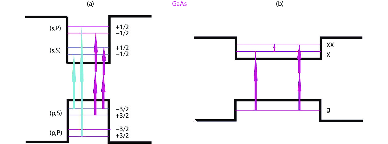
    Fig. 2. (Color online) Simplified schemes of optical transitions from different single photon sources. (a) Electron and hole confined states in a QD. The left indices show the band and envelope orbital symmetries, respectively. The right indices indicate the spin states. (b) Electron and hole confined states in a bigger QD compared with (a). Excitons and biexcitons are indicated. It should be noted that only absorption is illustrated in (a) and (b).
    (Color online) (a) Image of the bright spots showing individual QDs taken with an InGaAs camera and spectrum of the QD circled in a with exciton (X), biexciton (XX), positively charged exciton (X+) and negatively charged exciton (X-) labelled[75]. (b) The measured unnormalized correlation function [70], reprinted with permission from Ref. [70]. Copyright ©2000, The American Association for the Advancement of Science. (c) The comparison of photon extraction efficiency with pump power and photon purity from Ref. [25], Copyright ©2016, American Physical Society. (d) Two-photon interference demonstrated from the small area of peak 3[76]. Copyright ©2002, with permission from Springer Nature. (e) Resonance fluorescence of GaAs Quantum dots with near-unity photon indistinguishability. Reproduced from Ref. [32] with permission, Copyright ©2019, American Chemical Society.
    Fig. 3. (Color online) (a) Image of the bright spots showing individual QDs taken with an InGaAs camera and spectrum of the QD circled in a with exciton (X), biexciton (XX), positively charged exciton (X+) and negatively charged exciton (X-) labelled[75]. (b) The measured unnormalized correlation function [70], reprinted with permission from Ref. [70]. Copyright ©2000, The American Association for the Advancement of Science. (c) The comparison of photon extraction efficiency with pump power and photon purity from Ref. [25], Copyright ©2016, American Physical Society. (d) Two-photon interference demonstrated from the small area of peak 3[76]. Copyright ©2002, with permission from Springer Nature. (e) Resonance fluorescence of GaAs Quantum dots with near-unity photon indistinguishability. Reproduced from Ref. [32] with permission, Copyright ©2019, American Chemical Society.
    (Color online) (a) Simulation of the electromagnetic field of a crystal photonic waveguide. (b) Microstructure of a bull’s eye cavity and simulation of the single-photon extraction efficiency and Purcell factor as a function of photon emission wavelength of the cavity. Reprinted with permission from Ref. [85]. Copyright ©2019, American Physical Society. (c) Microplillar cavity used in Ref. [25], copyright ©2016, American Physical Society. (d) Schematic diagram of the waveguide-coupled quantum dot–photonic crystal cavity system. Reprinted with permission from Ref. [47]. Copyright ©2018 Springer Nature. (e) and (f) illustrated a mode-gap cavity depicted in Ref. [86].
    Fig. 4. (Color online) (a) Simulation of the electromagnetic field of a crystal photonic waveguide. (b) Microstructure of a bull’s eye cavity and simulation of the single-photon extraction efficiency and Purcell factor as a function of photon emission wavelength of the cavity. Reprinted with permission from Ref. [85]. Copyright ©2019, American Physical Society. (c) Microplillar cavity used in Ref. [25], copyright ©2016, American Physical Society. (d) Schematic diagram of the waveguide-coupled quantum dot–photonic crystal cavity system. Reprinted with permission from Ref. [47]. Copyright ©2018 Springer Nature. (e) and (f) illustrated a mode-gap cavity depicted in Ref. [86].
    (Color online) Purity and indistinguishability as a function of brightness summarized from Table1 with a trend indicated by red-dotted lines. Red triangles are non-resonant excitation while black squares are SPEs with resonant excitation. The blue circle is from hBN and the light blue squares are photon-pair SPEs.
    Fig. 5. (Color online) Purity and indistinguishability as a function of brightness summarized from Table1 with a trend indicated by red-dotted lines. Red triangles are non-resonant excitation while black squares are SPEs with resonant excitation. The blue circle is from hBN and the light blue squares are photon-pair SPEs.
    (Color online) (a) Schematics of a LPCVD setup to produce hBN film where ammonia borane is used as a CVD precursor. (b) A confocal PL map showing hBN luminescence. (c) hBN single photon measurement with g2(0) within 0.5, reprinted with permission from Ref. [123]. Copyright ©2019, American Chemical Society.
    Fig. 6. (Color online) (a) Schematics of a LPCVD setup to produce hBN film where ammonia borane is used as a CVD precursor. (b) A confocal PL map showing hBN luminescence. (c) hBN single photon measurement with g2(0) within 0.5, reprinted with permission from Ref. [123]. Copyright ©2019, American Chemical Society.
    ReferenceSourcePhotonic structureWavelength (nm)Lifetime (ns)Operation temperature ExcitationBlensg(2)(0) MEntanglement fidelity
    * denotes the brightniess of hBN after transfer comparing to its origianl brightness. Resonant and non-resonant excitation is highlighted by black and red with entangled SPE in light blue, respectively.
    [52] (2013) InGaAsMicropillar9310.265–0.27010Non-resonant0.79±0.08 0.53±0.05 0.050.55±0.05 0.92±0.10
    [72] (2015) InGaAsAdiabatic pillar9450.14±0.0420Non-resonant0.74±0.050.10±0.030.75±0.05
    [50] (2015) InGaAsMicrolens932~16Non-resonant0.23±0.03<0.010.80±0.07
    [51] (2015) InGaAsBulls-eye cavities9070.526Non-resonant0.48±0.050.009±0.005
    [73] (2016) InGaAsMicropillar892.60.1624.3Non-resonant0.3340.0270.921
    [26] (2016) InGaAsConnected pillar890 w/electrical tuned0.08–0.124Resonant0.154±0.0150.0028±0.00120.989±0.004 0.9956±0.0045
    [25] (2016) InGaAsMicropillar897.440.08410Resonant0.330.009±0.0020.959±003 0.978±0.004
    [114] (2017) GaNGallium nitride crystal1085–13400.736±0.004RoomNon-resonant0.05±0.02
    [123] (2017) InGaNN/A420.50.156130Non-resonant0.18
    [47] (2018) InGaAsPhotonic crystal cavities9150.0227± 0.0009 4Resonant0.410.026±0.0070.939±0.033
    [126] (2018) hBNPlasmonic nanocavity arrays566.040.375RoomNon-resonant0.5347*0.033±0.047
    [63] (2018) GaAsLow-Q planar cavity7930.1254Resonant0.50.000075± 0.000016
    [134] (2018) InAsPTapered InP nanowire12551.34Non-resonant0.280.03
    [131] (2016) hBNN/A660RoomNon-resonant0.3
    [74] (2019) InGaAsMicropillar8741.5Resonant~0.70.05±0.020.976±0.001
    [32] (2019) GaAsDBR7890.196±0.0025Resonant0.2±0.0320.0025±0.00020.95
    [88] (2018) GaAsBroadband optical antenna780.3, 781.6<0.24Resonant0.3720.002±0.0020.9
    [90] (2019) GaAsBragg grating bull’seye cavity770, 7720.063.2Resonant0.65±0.040.001±0.0010.901±0.0030.88±0.02
    [89] (2019) InGaAsBragg grating bull’seye cavity879.4, 8810.06644Resonant0.59±0.010.014±0.0010.9±0.010.9±0.01
    Table 1. Characteristics of III–V compound-based single photon emitters.
    Xu Wang, Lei Xu, Yun Jiang, Zhouyang Yin, Christopher C. S. Chan, Chaoyong Deng, Robert A. Taylor. III–V compounds as single photon emitters[J]. Journal of Semiconductors, 2019, 40(7): 071906
    Download Citation