
Jing Liu, Mian Zheng, Zhengjun Xiong, Zhiyuan Li. 3D dynamic motion of a dielectric micro-sphere within optical tweezers[J]. Opto-Electronic Advances, 2021, 4(1): 200015
- Opto-Electronic Advances
- Vol. 4, Issue 1, 200015 (2021)
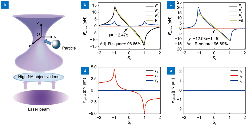
Fig. 1. (a ) Schematic of basic optical tweezers. A single laser beam is focused by a high numerical aperture objective lens to form a stable optical trap for microscale particle. (b ) and (c ) illustrate the calculated optical force acting on a micro-sphere when it moves along the x-axis and z-axis, respectively, in the optical tweezers at the laser power P = 10 mW. Here, the two most important features of optical tweezers are shown: the maximum reverse axial force that characterizes the strength of the trap, and spring constants (the slope of the fit line). (d ) and (e ) display the calculated optical torque acting on a micro-sphere when it moves along the x-axis and z-axis, respectively.
![The dynamic process of the micro-sphere in an optical tweezers. Plots of the (a) position, (b) velocity, (c) angular velocity, and (d) optical force versus time under the initial condition of r0=[0,0,1] μm, v0=[0,0,0] μm/s, ϕ0=[0,0,0] rad, and ω0=[0,0,0] rad/s.](/richHtml/OEA/2021/4/1/200015/2_oea-2020-0015-Lizhiyuan-2.jpg)
Fig. 2. The dynamic process of the micro-sphere in an optical tweezers. Plots of the (a ) position, (b ) velocity, (c ) angular velocity, and (d ) optical force versus time under the initial condition of r 0=[0,0,1] μm, v 0=[0,0,0] μm/s, ϕ 0=[0,0,0] rad, and ω 0=[0,0,0] rad/s.
Fig. 3. Mechanical motion dynamics of the micro-sphere at different initial positions in the horizontal trapping plane. (a ) The x-directional trajectories of the micro-sphere at different initial positions in the x-axis in the optical tweezers with r0x=0.5, 1.0, 1.5, 1.8, 1.9, and 2.0 μm. (b )−(d ) display the temporal evolution of the x- and y- and z- directional trajectory, optical force, drag force, and resultant force, respectively, when the micro-sphere is set at the initial position r0x=1.9 μm. (e ) and (f ) display the temporal evolution of the optical force and the drag force, and the resultant force, respectively, when r0x=2.0 μm.
Fig. 4. The 3D trajectories of the micro-sphere in the optical tweezers at different initial positions in the x-axis with r0x= 0.5, 1.0, 1.5, 1.8, 1.9, and 2 μm .
Fig. 5. Mechanical motion dynamics of the micro-sphere at different initial positions along the optical axis . (a ) The z-directional trajectories of the micro-sphere at different initial positions in the z-axis in the optical tweezers with r0x=−2.0, −1.5, −1.0, −0.5, 1.0, 1.4, 1.6, 1.7, 1.75 and 1.9 μm. (b ) and (c ) The sketches of the optical force and the drag force, and the resultant force over time, respectively, when the micro-sphere is set at the initial position r0x=1.7 μm.
Fig. 6. The 3D trajectories of the micro-sphere at different initial velocities in the x-axis in the optical tweezers with v0x=100, 1×10⁴, 1×10⁶, 5×10⁶, 7.5×10⁶, 7.75×10⁶, and 8×106 μm/s .
Fig. 7. (a ) The 3D trajectories of a micro-sphere at different initial velocities in the z-axis with v0x=1×10⁶, 5×10⁶, 6×10⁶, and 6.5×106 μm/s, when the initial position is r 0x=[1,0,0] μm. The plots of (b ) the optical force and drag force, and (c ) the resultant force over time of the micro-sphere when v0=[6.5 × 106,0,0] μm/s, and r 0x=[1,0,0] μm.

Set citation alerts for the article
Please enter your email address
© Copyright 2018-2021 | Chinese Laser Press. All Rights Reserved 沪ICP备15018463号-20