• Opto-Electronic Advances
  • Vol. 4, Issue 5, 200006-1 (2021)
Minkyung Kim1, Dasol Lee1, Younghwan Yang1, and Junsuk Rho1、2、*
Author Affiliations
  • 1Department of Mechanical Engineering, Pohang University of Science and Technology (POSTECH), Pohang 37673, Republic of Korea
  • 2Department of Chemical Engineering, Pohang University of Science and Technology (POSTECH), Pohang 37673, Republic of Korea
  • show less
    DOI: 10.29026/oea.2021.200006 Cite this Article
    Minkyung Kim, Dasol Lee, Younghwan Yang, Junsuk Rho. Switchable diurnal radiative cooling by doped VO2[J]. Opto-Electronic Advances, 2021, 4(5): 200006-1 Copy Citation Text show less
    Temperature-dependent material responses of VO2. (a) Schematic of temperature-dependent phase. (b) Permittivity at 2 μm when Tc = 298 K. Shaded area represents transition regime. (c) Real and (d) imaginary part of permittivity in transition regime.
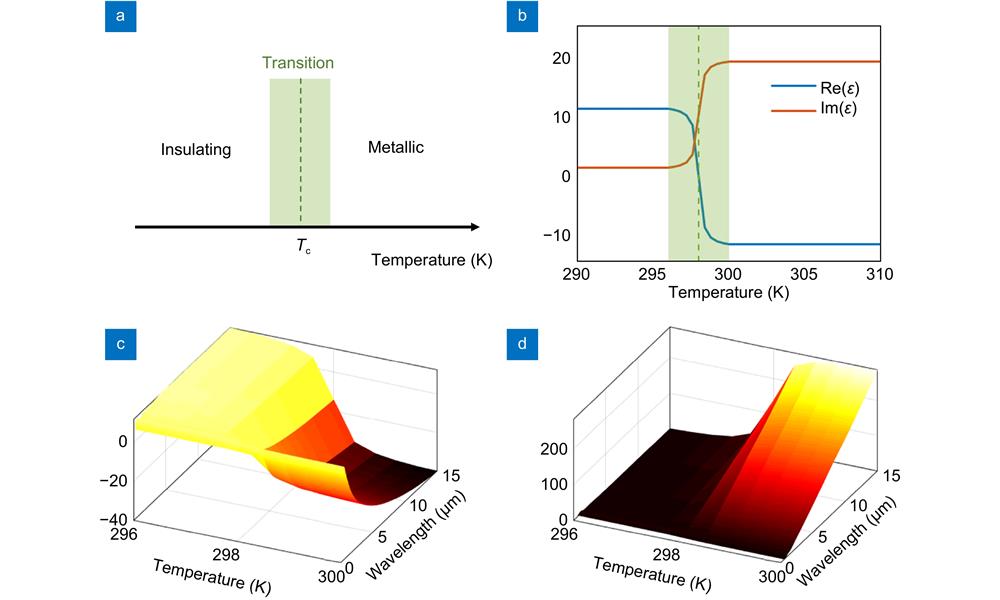
    Fig. 1. Temperature-dependent material responses of VO2. (a) Schematic of temperature-dependent phase. (b) Permittivity at 2 μm when Tc = 298 K. Shaded area represents transition regime. (c) Real and (d) imaginary part of permittivity in transition regime.
    Design of the switchable radiative cooler. Emitter part consists of stacked layers of silver, silicon and VO2. Solar reflector part consists of three photonic crystals that have 4 pairs of PMMA and silicon. PCi is designed to suppress absorption at λi where λ1 = 0.52 μm, λ2 = 0.76 μm and λ3 = 1.18 μm. Thickness of each layer is λi/4n.
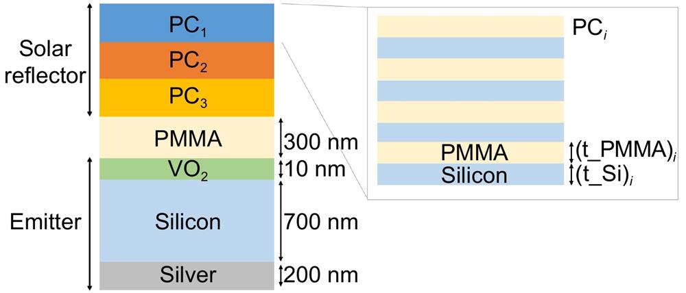
    Fig. 2. Design of the switchable radiative cooler. Emitter part consists of stacked layers of silver, silicon and VO2. Solar reflector part consists of three photonic crystals that have 4 pairs of PMMA and silicon. PCi is designed to suppress absorption at λi where λ1 = 0.52 μm, λ2 = 0.76 μm and λ3 = 1.18 μm. Thickness of each layer is λi/4n.
    Absorptivity and reflectivity of the switchable radiative cooler. (a, b) Absorptivity and reflectivity of the emitter part when VO2 is in (a) metallic and (b) insulating state. (c) Absorptivity and reflectivity of the solar reflector part. Three arrows represent the target wavelengths of three photonic crystals. (d, e) Absorptivity and reflectivity of the switchable radiative cooler when VO2 is in (d) metallic and (e) insulating state. Incident angle is zero. (f) Absorptivity of the switchable radiative cooler when VO2 is metallic.
    Fig. 3. Absorptivity and reflectivity of the switchable radiative cooler. (a, b) Absorptivity and reflectivity of the emitter part when VO2 is in (a) metallic and (b) insulating state. (c) Absorptivity and reflectivity of the solar reflector part. Three arrows represent the target wavelengths of three photonic crystals. (d, e) Absorptivity and reflectivity of the switchable radiative cooler when VO2 is in (d) metallic and (e) insulating state. Incident angle is zero. (f) Absorptivity of the switchable radiative cooler when VO2 is metallic.
    Cooling flux of the radiative cooler under normal incidence of solar energy when Tamb = 303 K. (a, b) Cooling flux when permittivity of VO2 is assumed to be (a) static and (b) dynamic. Shaded area represents the transition regime.
    Fig. 4. Cooling flux of the radiative cooler under normal incidence of solar energy when Tamb = 303 K. (a, b) Cooling flux when permittivity of VO2 is assumed to be (a) static and (b) dynamic. Shaded area represents the transition regime.
    Temperature variation in time. (a) Temperature and (b) cooling flux in time for initial temperature of 280 K to 320 K with 5 K step. Temperature indicate the initial temperature of the cooler. Tamb = 303 K. (c, d) A cycle of temperature of a day. (c) Tamb and solar irradiance of July 15, 2018 in Pohang, Korea. (d) Temperature of switchable radiative cooler (blue) and the static radiative cooler when radiative cooling is assumed to be turned on (orange) and off (yellow). Tamb is shown as a reference (black). Initial temperature of the cooler is set equal to the initial Tamb.
    Fig. 5. Temperature variation in time. (a) Temperature and (b) cooling flux in time for initial temperature of 280 K to 320 K with 5 K step. Temperature indicate the initial temperature of the cooler. Tamb = 303 K. (c, d) A cycle of temperature of a day. (c) Tamb and solar irradiance of July 15, 2018 in Pohang, Korea. (d) Temperature of switchable radiative cooler (blue) and the static radiative cooler when radiative cooling is assumed to be turned on (orange) and off (yellow). Tamb is shown as a reference (black). Initial temperature of the cooler is set equal to the initial Tamb.
    PMMASiliconSilverSiO2VO2
    c (J/gK) 1.470.710.231.000.24
    ρ (g/cm-3) 1.182.3310.502.654.57
    Table 1. Specific heat and density of materials.
    Minkyung Kim, Dasol Lee, Younghwan Yang, Junsuk Rho. Switchable diurnal radiative cooling by doped VO2[J]. Opto-Electronic Advances, 2021, 4(5): 200006-1
    Download Citation