• Photonics Research
  • Vol. 12, Issue 3, 399 (2024)
Qi Wu1、2, Yixiao Zhu2、4、*, Xueyang Li1、5、*, Hexun Jiang2, Chen Cheng1, Mengfan Fu2, Yikun Zhang2, Qunbi Zhuge2, Zhaohui Li3, and Weisheng Hu1、2
Author Affiliations
  • 1Peng Cheng Laboratory, Shenzhen 518055, China
  • 2State Key Laboratory of Advanced Communication Systems and Networks, Department of Electronic Engineering, Shanghai Jiao Tong University, Shanghai 200240, China
  • 3School of Electronics and Information Technology and Guangdong Provincial Key Laboratory of Optoelectronic Information Processing Chips and Systems, Sun Yat-sen University, Guangzhou 510006, China
  • 4e-mail: yixiaozhu@sjtu.edu.cn
  • 5e-mail: xueyang.li@pcl.ac.cn
  • show less
    DOI: 10.1364/PRJ.498624 Cite this Article Set citation alerts
    Qi Wu, Yixiao Zhu, Xueyang Li, Hexun Jiang, Chen Cheng, Mengfan Fu, Yikun Zhang, Qunbi Zhuge, Zhaohui Li, Weisheng Hu. Four-dimensional direct detection receiver enabling Jones-space field recovery with phase and polarization diversity[J]. Photonics Research, 2024, 12(3): 399 Copy Citation Text show less
    Polarization-diverse full-field receiver structure. PBS, polarization beam splitter; OC, optical coupler; PD, photodiode; Ex, Ey, orthogonal polarizations.
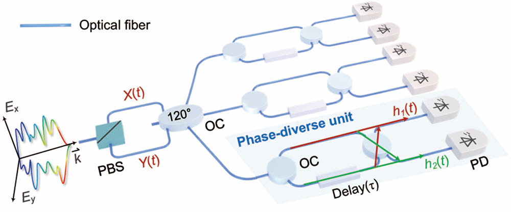
    Fig. 1. Polarization-diverse full-field receiver structure. PBS, polarization beam splitter; OC, optical coupler; PD, photodiode; Ex, Ey, orthogonal polarizations.
    (a) Experimental setup. ECL, external cavity laser; AWG, arbitrary waveform generator; DP IQM., dual-polarization IQ modulator; VOA, variable optical attenuator; EDFA, erbium-doped fiber amplifier; SMF, single-mode fiber; PC, polarization controller; PBS, polarization beam splitter; OC, 3×3 optical coupler; MZI, Mach–Zehnder interferometer; PD, photodiode; RTO, real-time oscilloscope. (b) DSP stacks. CCDM, constant composition distribution matcher; RRC, root-raised cosine; NGMI, normalized generalized mutual information; MIMO Equ. (w/ w/o Volterra), MIMO equalization (with/without Volterra). (c) Optical spectra of transmitted and received PDM optical signals. (d) Optical spectra of X- and Y-polarization signals with and without polarization fading phenomenon. PF, polarization fading.
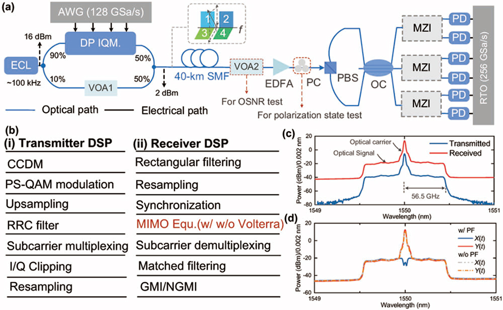
    Fig. 2. (a) Experimental setup. ECL, external cavity laser; AWG, arbitrary waveform generator; DP IQM., dual-polarization IQ modulator; VOA, variable optical attenuator; EDFA, erbium-doped fiber amplifier; SMF, single-mode fiber; PC, polarization controller; PBS, polarization beam splitter; OC, 3×3 optical coupler; MZI, Mach–Zehnder interferometer; PD, photodiode; RTO, real-time oscilloscope. (b) DSP stacks. CCDM, constant composition distribution matcher; RRC, root-raised cosine; NGMI, normalized generalized mutual information; MIMO Equ. (w/ w/o Volterra), MIMO equalization (with/without Volterra). (c) Optical spectra of transmitted and received PDM optical signals. (d) Optical spectra of X- and Y-polarization signals with and without polarization fading phenomenon. PF, polarization fading.
    Electrical spectra of the six received photocurrents (a) with polarization fading and (b) without polarization fading. ik(t) (k=1−6) are the six received photocurrents. (c) Electrical spectra of the recovered X- and Y-polarization signals. (d) Frequency response for two of 6×2 MIMO linear equalizers. (e) Measured NGMI and GMI versus CSPR in the 40-km transmission case. (f) Net data rate and GMI versus entropy of signal source.
    Fig. 3. Electrical spectra of the six received photocurrents (a) with polarization fading and (b) without polarization fading. ik(t) (k=16) are the six received photocurrents. (c) Electrical spectra of the recovered X- and Y-polarization signals. (d) Frequency response for two of 6×2 MIMO linear equalizers. (e) Measured NGMI and GMI versus CSPR in the 40-km transmission case. (f) Net data rate and GMI versus entropy of signal source.
    (a) Measured NGMI versus OSNR with MIMO linear and nonlinear equalization in the BTB case. (b) Measured NGMI versus OSNR with MIMO linear and nonlinear equalization after 40-km SMF transmission. (c) NGMIs of the four signal bands over 50 measurements with randomly varying polarization state. (d) Constellations of the four signal bands.
    Fig. 4. (a) Measured NGMI versus OSNR with MIMO linear and nonlinear equalization in the BTB case. (b) Measured NGMI versus OSNR with MIMO linear and nonlinear equalization after 40-km SMF transmission. (c) NGMIs of the four signal bands over 50 measurements with randomly varying polarization state. (d) Constellations of the four signal bands.
    (a) Experimental setup. ECL, external cavity laser; AWG, arbitrary waveform generator; DP IQM., dual-polarization IQ modulator; VOA, variable optical attenuator; EDFA, erbium-doped fiber amplifier; SMF, single-mode fiber; PBS, polarization beam splitter; OC, 3×3 optical coupler; PD, photodiode; EA, electrical amplifier; RTO, real-time oscilloscope. D1, D2, D3, three dispersive elements with a dispersion value of −300 ps/nm. (b) DSP stacks. RC, raised cosine; MIMO Equ. (w/ w/o Volterra), MIMO equalization (with/without Volterra). (c) Optical spectra of PDM signals in the BTB and 80-km SMF case. (d) Optical spectra of X- and Y-polarization signals with and without polarization fading phenomenon.
    Fig. 5. (a) Experimental setup. ECL, external cavity laser; AWG, arbitrary waveform generator; DP IQM., dual-polarization IQ modulator; VOA, variable optical attenuator; EDFA, erbium-doped fiber amplifier; SMF, single-mode fiber; PBS, polarization beam splitter; OC, 3×3 optical coupler; PD, photodiode; EA, electrical amplifier; RTO, real-time oscilloscope. D1, D2, D3, three dispersive elements with a dispersion value of 300  ps/nm. (b) DSP stacks. RC, raised cosine; MIMO Equ. (w/ w/o Volterra), MIMO equalization (with/without Volterra). (c) Optical spectra of PDM signals in the BTB and 80-km SMF case. (d) Optical spectra of X- and Y-polarization signals with and without polarization fading phenomenon.
    (a) Electrical spectra of the six received photocurrents. (b) Measured NGMI versus CSPR in the 80-km transmission case. (c) Measured NGMI versus OSNR with MIMO linear and nonlinear equalization in the BTB case. (d) Measured NGMI versus OSNR with MIMO linear and nonlinear equalization after 80-km SMF transmission. (e) Constellations of the four signal bands.
    Fig. 6. (a) Electrical spectra of the six received photocurrents. (b) Measured NGMI versus CSPR in the 80-km transmission case. (c) Measured NGMI versus OSNR with MIMO linear and nonlinear equalization in the BTB case. (d) Measured NGMI versus OSNR with MIMO linear and nonlinear equalization after 80-km SMF transmission. (e) Constellations of the four signal bands.
    Net ESE and net data rate comparison in various direct detection systems beyond 100 Gbit/s. Direct detection systems with modulation dimensions from 1-D to 4-D are compared.
    Fig. 7. Net ESE and net data rate comparison in various direct detection systems beyond 100 Gbit/s. Direct detection systems with modulation dimensions from 1-D to 4-D are compared.
    Polarization-diverse full-field receiver structure based on dispersion elements. PBS, polarization beam splitter; OC, 3×3 optical coupler; DE, dispersive element; PD, photodiode.
    Fig. 8. Polarization-diverse full-field receiver structure based on dispersion elements. PBS, polarization beam splitter; OC, 3×3 optical coupler; DE, dispersive element; PD, photodiode.
    Qi Wu, Yixiao Zhu, Xueyang Li, Hexun Jiang, Chen Cheng, Mengfan Fu, Yikun Zhang, Qunbi Zhuge, Zhaohui Li, Weisheng Hu. Four-dimensional direct detection receiver enabling Jones-space field recovery with phase and polarization diversity[J]. Photonics Research, 2024, 12(3): 399
    Download Citation