
Qi Wu, Yixiao Zhu, Xueyang Li, Hexun Jiang, Chen Cheng, Mengfan Fu, Yikun Zhang, Qunbi Zhuge, Zhaohui Li, Weisheng Hu. Four-dimensional direct detection receiver enabling Jones-space field recovery with phase and polarization diversity[J]. Photonics Research, 2024, 12(3): 399
- Photonics Research
- Vol. 12, Issue 3, 399 (2024)
Abstract
1. INTRODUCTION
Lightwaves play a critical role in data centers, facilitating high-capacity information transmission and extended reach [1–3]. Optical communication systems can be generally categorized into direct detection and coherent detection, depending on the presence of the local oscillator (LO) [4]. Since the advent of laser sources, the intensity modulation and direct detection (IM-DD) system has been widely implemented as a low-cost solution [5,6]. However, the square-law detection of the photodiode (PD) limits not only the encoded degree of freedom to one dimension but also the transmission distance due to the power fading effect induced by fiber chromatic dispersion [7]. By contrast, coherent detection methods exploit both phase and polarization diversities with the aid of LO beating, resulting in quadrupled electrical spectral efficiency and capacity [8–10]. With the introduction of advanced digital signal processing (DSP) algorithms, linear optical-to-electrical mapping enables fiber impairment compensation in the coherent system, thereby endowing it with transoceanic and terrestrial transmission capabilities [11–13]. This makes coherent detection particularly well-suited for long-haul transmission scenarios where polarization mode dispersion accumulates, in comparison to direct detection. Nevertheless, narrow-linewidth laser sources are desired to suppress the phase noise [14], which hinders its massive deployment in cost-sensitive use cases such as data-center optical interconnects.
To fully leverage the high spectral efficiency advantage of coherent detection while maintaining the LO-free property of direct detection, phase- and polarization-diverse receivers that enable digital compensation of transmission impairments based on the reconstructed signal field are highly desirable. Pioneer efforts have been reported, known as the differential self-coherent receiver, which relies on the beating between a signal and its delay [15]. Recently, several carrier-assisted direct detection schemes have garnered increasing attention, including the Kramers–Kronig receiver [16], carrier-assisted differential detection [17], and asymmetric self-coherent detection [18]. These techniques can reconstruct the optical field from the linear signal–carrier beating component, allowing for phase diversity without the need for an LO.
In addition to phase retrieval, the polarization fading (PF) phenomenon poses a fundamental obstacle to accessing polarization division multiplexing [19]. Unlike the coherent detection scheme where an LO with controllable polarization is employed at the receiver, direct detection schemes deliver a co-propagating optical carrier together with the signal at the transmitter. The random polarization rotation during fiber transmission can lead to the absence of an optical carrier on one polarization such that the receiver fails to detect the polarization-division-multiplexed (PDM) signals. Note that the capacity degradation caused by PF cannot be compensated for in the DSP even with the multi-input–multi-output (MIMO) equalization algorithm. Over the last decade, the Stokes vector receiver has been extensively studied as a promising solution to polarization fading [20–28]. However, the common phase of the two orthogonal polarizations is lost in the real-valued three-dimensional Stokes space. Some attempts have been made to exploit the fourth dimension by adding an extra optical hybrid to the original Stokes vector receiver [23,28]. This approach extracts the inter-polarization differential phase for carrier-less signals but cannot perform full field recovery, limiting the transmission reach. Alternatively, the modified Gerchberg–Saxton algorithm has been introduced in optical communications [29,30]. It reconstructs the dual-polarization optical field through digital propagation between dispersive projections but exhibits slower convergence, requiring hundreds of iterations [31].
Sign up for Photonics Research TOC. Get the latest issue of Photonics Research delivered right to you!Sign up now
Here we propose and demonstrate a four-dimensional Jones-space optical field recovery (4-D JSFR) scheme with phase and polarization diversity. The 4-D JSFR receiver consists of a optical coupler in order to ensure the satisfied carrier-to-signal power ratio (CSPR) threshold of both polarizations and three Mach–Zehnder interferometers (MZIs) that are responsible for recovering both in-phase and quadrature information. As a proof-of-concept experiment, we demonstrate the transmission of 873.7-Gbit/s net data rate with PDM probabilistically shaped 64-ary quadrature amplitude modulation (PS-64QAM) over 40-km single-mode fiber (SMF) using only a linear feed forward equalizer. It has achieved the highest net electrical spectral efficiency of 15.45 (bit/s)/Hz among the existing direct detection systems, to the best of our knowledge. The proposed 4-D JSFR quadruples the spectral efficiency of IM-DD and extends the reach beyond the power fading limit—on par with the advanced intradyne coherent detection without requiring a narrow-linewidth LO. The concept of JSFR introduces innovation to the theory of field recovery, with the potential to influence the performance of direct detection schemes, bringing them closer to the theoretical coherent limit. Additionally, it may provide practical insights for the design of high-speed and spectrally efficient optical modules.
2. CONCEPT OF JONES-SPACE OPTICAL FULL-FIELD RECOVERY
Figure 1 depicts the structure of the proposed polarization-diverse full-field receiver for detecting the PDM complex-valued double sideband signals. The phase-diverse unit in this receiver enables the recovery of the in-phase and quadrature information using the time-domain impulse response of and . The detected photocurrents [ and ] from two branches can be written as
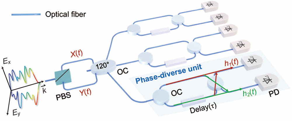
Figure 1.Polarization-diverse full-field receiver structure. PBS, polarization beam splitter; OC, optical coupler; PD, photodiode;
In direct detection systems with a co-propagating carrier, CSPR is considered a critical parameter for SSBI cancellation. The SSBI impairment can be regarded as a nonlinear perturbation assuming the CSPR value exceeds the threshold , which is related to the modulated signal and channel characteristics. Based on this, various digital linearization algorithms including iterative reconstruction [32–34], Volterra nonlinear equalization [35], and a deep neural network [36], can be applied to eliminate the SSBI. In our work, we employ a diagonal terms-only MIMO Volterra equalizer as an integrated tool capable of both linear and nonlinear processing, owing to its low-complexity and non-iterative nature.
For the reception of PDM signals, we assume, without loss of generality, that the optical carrier is linearly polarized, situated at a angle between X- and Y-polarizations. In principle, this scheme remains applicable for carriers in arbitrary states of polarization (SOPs) due to the unitary properties of the Jones matrix. As such, the Jones vector of the transmitted carrier-assisted dual-polarization optical field is denoted as [, ], where and are independent complex-valued signals with equal power on the X- and Y-polarizations, respectively. is the continuous wave. In such a dual-polarization case, the CSPR is defined as the power ratio between the two carriers () and the PDM signals of two polarizations (, ), shown in Eq. (4):
Generally, the polarization effect in short-reach optical communications can be modeled in Jones space as the Caley–Klein form [2]. After SMF transmission, the received Jones vector can be written as
In order to overcome the polarization fading problem, we use a optical coupler to mix and . The three optical field outputs can be expressed as
3. TRANSMISSION EXPERIMENT
A. Experimental Setup for Four-Dimensional Direct Detection
Figure 2(a) shows the experimental setup for the proposed 4-D JSFR scheme using MZIs. The procedures of the offline DSP for signal modulation, optical field recovery, and signal demodulation are shown in Fig. 2(b). At the transmitter, an arbitrary waveform generator (Keysight M8199A, 65-GHz 3-dB bandwidth) operating at 128 GSa/s is used to generate 53-GBd PDM PS-64QAM symbols shaped by a root-raised cosine filter with a roll-off factor of 0.01. We adopt digital subcarrier multiplexing to avoid the singularity of the receiver transfer function [38]. The four independent signal bands are up-converted to the intermediate frequency of to reserve a 3-GHz guard band. The electrical signals are loaded into an integrated dual-polarization IQ modulator (IDPhotonics) with a 3-dB bandwidth of 60 GHz to modulate the light from the external cavity laser (ECL, IDPhotonics) with a linewidth of , centered at 1550.06 nm. Another 10% branch from ECL is employed as the optical carrier with uncontrolled SOP. Herein, the variable optical attenuator (VOA1) is used to adjust the CSPR to satisfy the condition of optical field recovery. The modulated optical field is combined with the optical carrier and then launched into the 40-km single-mode fiber link. The launch power is 2 dBm. The four signal bands are indexed as in the inset of Fig. 2(a).
![]()
Figure 2.(a) Experimental setup. ECL, external cavity laser; AWG, arbitrary waveform generator; DP IQM., dual-polarization IQ modulator; VOA, variable optical attenuator; EDFA, erbium-doped fiber amplifier; SMF, single-mode fiber; PC, polarization controller; PBS, polarization beam splitter; OC,
The optical signal is first boosted to 22 dBm after 40-km SMF transmission. Here, the optical signal-to-noise ratio (OSNR) and SOPs of the optical signal are adjusted for testing the system performance by VOA2 and polarization controller, respectively, which are not necessary for this scheme. Subsequently, the proposed polarization-diverse full-field receiver with an additional insertion loss of 6 dB is used to detect the dual-polarization optical field. The transfer function of MZI is realized using the Fourier processor function of a programmable optical processer (II-IV 4000A) in the frequency domain [i.e., ]. The optical delay () should be chosen to ensure that the transfer function does not have zeros in the signal band. Additionally, optimization is needed for achieving the maximum signal-to-noise ratio within the signal bandwidth. In this experiment, it is optimized to 8 ps. After the photoelectric conversion using single-ended PDs (XPD3210R), the six electrical waveforms are captured by six channels of two synchronized 256-GSa/s real-time oscilloscopes (RTOs, Keysight UXR0594AP, 10-bit resolution) operating in multi-scope mode. At the receiver-side DSP, the electrical waveforms are digitally filtered to emulate a receiver with a rectangular bandwidth of 56.53 GHz and then resampled to 159 GSa/s. After frame synchronization, the six digital waveforms are processed by an MIMO equalizer, performing optical field recovery, polarization demultiplexing, and channel-matched equalization simultaneously. Linear and nonlinear equalization methods are tested, including a 91-tap feed-forward equalizer and a 113-tap () third-order sparse Volterra equalizer with diagonal kernels. The filter taps are updated using the recursive least squares algorithm with a forgetting factor of 0.999 based on 2000 training symbols. The reconstructed dual-polarization optical signal fields are then demodulated to the baseband for matched filtering. The generalized mutual information (GMI) and normalized generalized mutual information (NGMI) of signal bands 1–4 are calculated using the bit-wise log-likelihood ratio [39].
The transmitted and received optical spectra in the back-to-back (BTB) configuration and after 40-km SMF transmission are shown in Fig. 2(c) at a resolution of 0.002 nm. Approximately half of the optical signal bandwidth is , equivalent to bandwidth around 1550-nm wavelength, including a 53.5-GHz signal bandwidth and a 3-GHz guard band. Figure 2(d) compares the optical spectra of both polarizations with and without polarization fading. It shows that without polarization fading, the optical carrier power difference between X- and Y-polarizations is negligible. However, when polarization fading occurs, one of the two polarizations may become carrier-less. This issue will be resolved after mixing in the optical coupler; otherwise, the carrier-less polarization cannot be recovered using the principle described in Eqs. (2) and (3) since the linear signal–carrier beating term is lost.
B. CSPR and Source Entropy Optimization
The electrical spectra of the received photocurrents provide insight into the frequency components of the signal and noise. Figure 3(a) shows the spectra with polarization fading. We observe from this figure that the signal–carrier beating term dominates the spectrum. In Fig. 3(b), which shows the spectra without polarization fading, we can see that the signal–carrier beating term is also dominant. This means that the JSFR receiver only needs to have a bandwidth that is sufficient to capture the linear signal replica, and not necessarily the entire frequency range of the received signal. Even though the SSBI outside of the receiver’s bandwidth is not directly captured, it does not distort the signal–carrier beating term and, therefore, does not impact the overall system performance. Therefore, the JSFR receiver can achieve high performance with a relatively narrow electrical bandwidth and at a reduced cost. Figure 3(c) displays the electrical spectra of the recovered X- and Y-polarization signals, demonstrating the effectiveness of adaptive equalization in signal recovery. In Fig. 3(d), we provide an intuitive representation of the frequency response for two of the MIMO linear equalizers ( and ), along with simulation results for comparison. The orange region corresponds to the modulated signal band. The results illustrate the adaptive equalization’s capability to estimate the MZI transfer function and the attenuation of bandwidth in the high-frequency range.
![]()
Figure 3.Electrical spectra of the six received photocurrents (a) with polarization fading and (b) without polarization fading.
As a direct detection scheme with a co-propagated carrier, the CSPR is a critical factor that needs to be optimized in the presence of SSBI impairment. Note that we attenuate the carrier power in order to achieve a CSPR lower than 16 dB, whereas, for a CSPR higher than 16 dB, we choose to attenuate the signal power due to the insertion loss of the DP-IQM and 90:10 coupler. A higher CSPR can degrade the effective OSNR, while a lower CSPR may not satisfy the perturbation assumption needed for accurate nonlinear SSBI compensation. In order to identify the optimal value for 40-km transmission, the CSPR is swept from 12 to 17 dB, and the optimal CSPR for dual-polarization optical field recovery is around 16 dB, as shown in Fig. 3(e). Unlike long-haul transmission, the OSNR is limited by optical noise introduced by multi-stage optical amplifiers. Short-distance scenarios such as data center optical interconnects have sufficiently high OSNR, allowing for a CSPR of 16 dB.
Probabilistic shaping [40] is a technique used to approach the linear Shannon limit by optimizing the probabilities of the constellation points. In this work, the probabilities of the outer constellation points are reduced to enlarge the Euclidean distance under the average power constraint. Four independent PS-64QAM symbol sequences with a length of 212,000 are generated based on the constant composition distribution matcher [41]. As shown in Fig. 3(f), the source entropy is optimized as 5.07 bit/symbol to maximize the achievable information rate in terms of GMI for this system. Additionally, the improvement in GMI brought about by nonlinear taps indicates that the impairment of SSBI has been effectively mitigated.
C. Evaluation of Tolerance to Polarization Rotation
In this subsection, the performance of the proposed 4-D JSFR receiver is evaluated under different SOPs. Two extreme cases, with and without polarization fading, are considered to test the robustness of the system against polarization rotation. To measure the system’s performance, we employ the NGMI, which provides a reliable predictor of post-forward error correction (FEC) performance, regardless of the source entropy of the PS-QAM signal [39]. Figure 4(a) investigates the NGMI as a function of OSNR in the BTB case. Using the optimal CSPR of 16 dB, the maximum attainable OSNR is about 48.5 dB. A comparison of the OSNR sensitivity curves reveals that NGMI performance is slightly better in the presence of PF compared to the case without PF. This improvement can be attributed to the polarization-state-varying CSPRs of the received optical fields, as derived in Eq. (10). In the PF case, the power of the signal–carrier beating terms is maximized, leading to a higher electrical signal-to-noise ratio. In this experiment, we consider a practical FEC with a code rate of 0.8402 (i.e., 19.02% overhead) and a corresponding NGMI threshold of 0.8798 [42]. The OSNR penalty is merely 0.2 dB at this NGMI threshold, implying that the proposed 4-D JSFR has a strong tolerance for polarization rotation. Thus, Fig. 4(a) also shows that linear equalization itself can reconstruct the optical field, and the nonlinear diagonal kernels suffice to eliminate the SSBI effectively. In the low-OSNR range, the performance impact of nonlinear kernels is limited, as optical noise, rather than SSBI, remains the primary impairment. However, in the high-OSNR range, nonlinear kernels play a crucial role in SSBI elimination, contributing to an improved NGMI. Figure 4(b) depicts the OSNR sensitivity of the JSFR receiver after 40-km SMF, covering the transmission distance of data center interconnects. With an OSNR beyond 44 dB, the NGMI threshold is reached under different SOPs, indicating a post-FEC error-free transmission. The receiver shows excellent performance in a realistic transmission scenario with 40-km SMF, and the penalty is less than 0.5 dB compared to the BTB case. These findings underscore the potential of the 4-D JSFR receiver for high-speed and high-capacity optical communication systems in various applications. The practical system is expected to perform reliably under changing polarization states. Here we measure the system performance under a randomly varying polarization state. The results at 46.5-dB OSNR are displayed in Fig. 4(c). An inset on the right displays the NGMI distribution across 50 measurements, revealing consistent and stable transmission performance. These findings demonstrate the robustness of the proposed system against polarization fading and its ability to perform reliably under varying polarization states. Figure 4(d) displays the recovered constellations of the four signal bands after 40-km SMF transmission. The constellations exhibit excellent quality and minimal distortion, confirming the efficacy of the proposed 4-D JSFR receiver in mitigating impairments caused by polarization fading and SSBI.
![]()
Figure 4.(a) Measured NGMI versus OSNR with MIMO linear and nonlinear equalization in the BTB case. (b) Measured NGMI versus OSNR with MIMO linear and nonlinear equalization after 40-km SMF transmission. (c) NGMIs of the four signal bands over 50 measurements with randomly varying polarization state. (d) Constellations of the four signal bands.
D. Supplementary Experimental Demonstration of 4-D JSFR Using Dispersive Elements
In this subsection, we offer an additional experimental validation of the 4-D JSFR utilizing a phase-diverse unit based on dispersive elements (DEs). The receiver structure and detailed principle are provided in Appendix B. Figure 5(a) illustrates the experimental setup using DEs. The procedures of the offline DSP are shown in Fig. 5(b). At the transmitter, an arbitrary waveform generator (Keysight M8194A, 45-GHz 3-dB bandwidth) operating at 120 GSa/s is used to generate 15-GBd PS-64QAM symbols shaped by a raised cosine filter with a roll-off factor of 0.01. The entropy of PS-64QAM is optimized as 4.4 bit/symbol. The four independent signal bands are up-converted to the intermediate frequency of to reserve a 3-GHz guard band. The electrical signals are loaded into an integrated dual-polarization IQ modulator (Neophotonics, 35-GHz 3-dB bandwidth) to modulate the light from the ECL with a linewidth of , centered at 1551.06 nm. Another branch from ECL is employed as the optical carrier with uncontrolled SOP. The modulated optical field is amplified by an EDFA with a noise figure of and then launched into the fiber link. The launch power is optimized as 8 dBm.
![]()
Figure 5.(a) Experimental setup. ECL, external cavity laser; AWG, arbitrary waveform generator; DP IQM., dual-polarization IQ modulator; VOA, variable optical attenuator; EDFA, erbium-doped fiber amplifier; SMF, single-mode fiber; PBS, polarization beam splitter; OC,
The optical signal is first boosted to 18 dBm after 80-km SMF transmission and then fed into the polarization-diverse full-field receiver for 4-D JSFR. The applied dispersion values of three dispersive elements (TDCMX-SM TERAXION) are set at about . After the photoelectric conversion, a 100-GSa/s RTO (Tektronix DPO75902SX, 8-bit resolution) with six synchronized channels is used to capture the electrical waveforms for offline DSP. The electrical amplifiers are employed in this setup to improve tolerance to the electrical noise. At the receiver-side DSP, the electrical waveforms are resampled to 60 GSa/s and then digitally filtered to emulate a receiver with a rectangular bandwidth of 18.15 GHz. After the frame synchronization, the six digital waveforms are fed into the MIMO linear or Volterra nonlinear equalizer to perform optical field recovery, polarization demultiplexing, and channel-matched equalization simultaneously. We also utilize Volterra nonlinear equalization to mitigate the SSBI impairment for the purpose of lowering computational complexity, compared with iterative algorithms. The reconstructed dual-polarization optical signal fields are demodulated to the baseband and then down-sampled. The NGMIs of signal bands 1–4 are calculated using the bit-wise log-likelihood ratio.
Figure 5(c) shows the received optical spectra in the BTB configuration and after an 80-km SMF transmission. About half of the optical signal bandwidth is around 0.145 nm, roughly equivalent to 18 GHz near 1550-nm wavelength, which includes a 15.15-GHz signal bandwidth and a 3-GHz guard band. In Fig. 5(d), we compare the optical spectra for both polarizations with and without polarization fading. It is clear that when polarization fading occurs, one of the polarizations loses its carrier, similar to the results shown in Fig. 2(d). The electrical spectra of the six received photocurrents are shown in Fig. 6(a). The signal–carrier beating term contributes to the main part of the received signal spectra, and the nonlinear SSBI spans a much wider spectrum than the signal bandwidth. Fortunately, the required bandwidth of the JSFR receiver only needs to be larger than the occupied bandwidth of linear signal replica, as the settings in the receiver-side DSP. We thus sweep the CSPR from 6 to 16 dB to identify the optimal value for 80-km transmission, shown in Fig. 6(b). It shows that the optimal CSPR is about 14 dB for Jones-space optical field recovery. Figure 6(c) displays the OSNR sensitivity of the proposed scheme with different polarization states in the BTB case. The experimental results of the dispersive-element-based 4-D JSFR are consistent with those based on MZIs. The OSNR penalty caused by polarization rotation is only 0.2 dB at the NGMI threshold of 0.8, implying that the proposed 4-D JSFR has a good tolerance for polarization rotation. Figure 6(d) displays the OSNR sensitivity of the proposed scheme with different polarization states in the 80-km SMF case. Compared with the BTB case, the field recovery ability of 4-D JSFR successfully brings the 80-km transmission penalty down to less than 0.3 dB. The recovered constellations of four signal bands after 80-km SMF transmission are displayed in Fig. 6(e). The excellent quality of constellations affirms the effectiveness of the proposed 4-D JSFR receiver in mitigating impairments. These results confirm that the phase-diverse unit of the proposed receiver can be adapted with other potential optical elements, and demonstrate the future possibilities of 4-D JSFR.
![]()
Figure 6.(a) Electrical spectra of the six received photocurrents. (b) Measured NGMI versus CSPR in the 80-km transmission case. (c) Measured NGMI versus OSNR with MIMO linear and nonlinear equalization in the BTB case. (d) Measured NGMI versus OSNR with MIMO linear and nonlinear equalization after 80-km SMF transmission. (e) Constellations of the four signal bands.
4. DISCUSSION
We highlight the achieved electrical spectral efficiency (ESE) in the experiment through the implementation of 4-D JSFR based on MZIs. Considering a practical FEC threshold of 0.8798 [42], linear and nonlinear equalization can both achieve a net data rate of 873.7 Gbit/s. The rectangular electrical bandwidth of the 4-D JSFR receiver is 56.53 GHz. Thus, the achieved ESE is . Figure 7 summarizes the net ESEs and data rate of state-of-the-art DD systems beyond 100 Gbit/s with 1-D to 4-D modulation. To the best of our knowledge, the 4-D JSFR achieves the highest electrical spectral efficiency among the existing direct detection systems. The achieved data rate supports single-wavelength 800-Gbit/s transmission and meets the requirements of next-generation Ethernet interface evolution.
![]()
Figure 7.Net ESE and net data rate comparison in various direct detection systems beyond 100 Gbit/s. Direct detection systems with modulation dimensions from 1-D to 4-D are compared.
Compared with the schemes in Refs. [23,28], a 40-km transmission distance can be supported with 4-D JSFR to fulfill the requirement of interconnection between large-scale data centers, which reveals its capability of optical field recovery for fiber chromatic dispersion compensation. In addition, unlike the modified Gerchberg–Saxton algorithm that reconstructs the optical field from the quadratic signal–signal beating term of carrier-less signal [31], 4-D JSFR successfully extracts the optical field from the linear signal–carrier beating term. Therefore, the required bandwidth of the receiver is almost halved with respect to signal bandwidth, resulting in an improved electrical spectral efficiency that is comparable to intradyne coherent detection.
In our experiment, MZIs and DEs are employed as the phase-diverse units used for retaining the I/Q components. In addition, other optical devices such as micro-ring resonators, optical all-pass filters, or silicon Bragg gratings [47] can also be used for this purpose. The choice of the device depends on the specific requirements of the system, such as the modulation bandwidth and the required level of integration. The key is to ensure that the device provides sufficient modulation bandwidth for high-capacity transmission. On-chip implementation of these devices can offer advantages in terms of size, power consumption, and cost.
It is worth noting that the LO-less advantage makes the polarization-diverse full-field receiver structure particularly attractive for the complementary metal oxide semiconductor (CMOS)-compatible silicon photonics platform [38,48]. Monolithic integration is within reach, especially for group-IV-element-based indirect band gap semiconductor material with low quantum efficiency.
The 4-D JSFR has resolved the polarization fading issue, which can be attributed to polarization mode coupling in single-mode fiber. For spatial division multiplexing, this methodology can also be employed to eliminate the fading phenomenon induced by spatial mode/core coupling in direct detection systems. Therefore, the JSFR scheme holds the potential to leverage higher physical dimensions in few-mode [49], orbital-angular-momentum ring-core [50], or multi-core fiber [51].
To summarize, this paper has described the concept of a four-dimensional direct detection receiver and experimental results of 15.45-(bit/s)/Hz electrical spectral efficiency over 40-km single-mode fiber transmission with dual-polarization complex-valued double sideband signal. We have achieved a net data rate of 873.7 Gbit/s using a single-wavelength optical source. The 4-D JSFR fully exploits the physical dimensions of light in single-mode fiber, almost quadrupling the conventional IM-DD system’s electrical spectral efficiency. Benefiting from optical field recovery, it also enables receiver-side digital compensation for chromatic dispersion and random polarization rotation, similar to coherent systems. It provides a powerful and practical solution without an LO, which is suitable for high-speed data center optical networks. The theoretical derivation and analysis to tackle polarization mode coupling issues are scalable to numerous spatial division multiplexing channels including few-mode, multi-core fibers, and their mixers. Beyond optical communications, Jones-space optical field recovery may have applications in optical metrology, imaging, and sensing systems. Its potential applications in high-speed data transmission suggest it could be a field of interest for future research.
APPENDIX A: THEORETICAL DERIVATION OF OPTICAL FIELD RECOVERY
We instantiate the time-domain impulse response of and using a Mach–Zehnder interferometer. The received photocurrents and can be denoted as
We add and , and exclude the direct current, acquiring the in-phase component , denoted as
Next, we subtract from , and exclude the direct component (DC) carrier–carrier beating term, acquiring the quadrature component , denoted as
Note that in Eqs. (
Finally, can be acquired from and with an adaptive nonlinear equalization such as widely used Volterra series.
APPENDIX B: SUPPLEMENTARY RECEIVER STRUCTURE BASED ON DISPERSIVE ELEMENTS
In addition to the MZI, we also instantiate the time-domain impulse response of and using a single DE. The modified polarization-diverse full-field receiver structure is depicted in Fig.
![]()
Figure 8.Polarization-diverse full-field receiver structure based on dispersion elements. PBS, polarization beam splitter; OC,
The dispersion element acts like an all-pass filter having a time-domain impulse response of and . After excluding the DC components, the detected photocurrents [ and ] from two branches can be written as
The time-domain impulse response of DE is decomposed into an in-phase part and a quadrature part correspondingly. Both Eqs. (
References
[3] M. Chagnon. Optical communications for short reach. J. Lightwave Technol., 37, 1779-1797(2019).
[8] C. Laperle, B. Villeneuve, Z. Zhang. Wavelength division multiplexing (WDM) and polarization mode dispersion (PMD) performance of a coherent 40 Gbit/s dual-polarization quadrature phase shift keying (DP-QPSK) transceiver. Optical Fiber Communication Conference, PDP16(2007).
[9] G. Charlet, J. Renaudier, M. Salsi. Efficient mitigation of fiber impairments in an ultra-long haul transmission of 40 Gbit/s polarization-multiplexed data, by digital processing in a coherent receiver. Optical Fiber Communication Conference, PDP17(2007).
[28] H. Ji, T. Ji, C. Sun. Four-dimensional direct detection receiver based on Stokes vector and differential polarization inner product. Asia Communications and Photonics Conference (ACP), T1B.1(2020).
[29] R. W. Gerchberg. A practical algorithm for the determination of phase from image and diffraction plane pictures. Optik, 35, 237-246(1972).
[30] J. R. Fienup. Phase retrieval algorithms: A comparison. Appl. Opt., 21, 2758-2769(1982).
[38] Y. Hu, X. Li, D. Mao. Transmission of net 200 Gbps/
[39] J. Cho, L. Schmalen, P. J. Winzer. Normalized generalized mutual information as a forward error correction threshold for probabilistically shaped QAM. European Conference on Optical Communication (ECOC), M2D.2(2017).
[42] J. Cho, L. Schmalen. Construction of protographs for large-girth structured LDPC convolutional codes. IEEE International Conference on Communications, 4412-4417(2015).
[43] X. Chen, J. Cho, G. Raybon. Single-wavelength and single-photodiode 700 Gb/s entropy-loaded PS-256-QAM and 200-GBaud PS-PAM-16 transmission over 10-km SMF. European Conference on Optical Communication (ECOC), Th3A-2(2020).
[44] S. T. Le, K. Schuh. 465 Gbps single side band direct detection transmission over 40 km of SSMF using a single-ended photodiode. Optical Fiber Communication Conference and Exhibition (OFC), F2D.5(2021).
[46] D. Che, S. Chandrasekhar, X. Chen. Single-channel direct detection reception beyond 1 Tb/s. Optical Fiber Communication Conference and Exhibition (OFC), Th4B.7(2019).

Set citation alerts for the article
Please enter your email address
© Copyright 2018-2021 | Chinese Laser Press. All Rights Reserved 沪ICP备15018463号-20