• Opto-Electronic Advances
  • Vol. 6, Issue 12, 230120 (2023)
Dingyu Xu1, Wenhao Xu2, Qiang Yang1, Wenshuai Zhang1, Shuangchun Wen1, and Hailu Luo1、*
Author Affiliations
  • 1Laboratory for Spin Photonics, School of Physics and Electronics, Hunan University, Changsha 410082, China
  • 2School of Physics and Chemistry, Hunan First Normal University, Changsha 410205, China
  • show less
    DOI: 10.29026/oea.2023.230120 Cite this Article
    Dingyu Xu, Wenhao Xu, Qiang Yang, Wenshuai Zhang, Shuangchun Wen, Hailu Luo. All-optical object identification and three-dimensional reconstruction based on optical computing metasurface[J]. Opto-Electronic Advances, 2023, 6(12): 230120 Copy Citation Text show less
    Scheme illustration of object identification and all-optical 3D reconstruction system. (a) A contour surface image of the object can be obtained in a single processing of the system. (b) High-contrast objects and low-contrast objects can be reconstructed by this all-optical computing metasurface system.
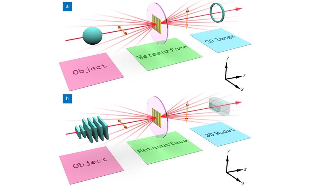
    Fig. 1. Scheme illustration of object identification and all-optical 3D reconstruction system. (a) A contour surface image of the object can be obtained in a single processing of the system. (b) High-contrast objects and low-contrast objects can be reconstructed by this all-optical computing metasurface system.
    Experimental demonstration of object identification ability. (a) Schematic diagram of the experimental optical path for object identification. L: lens; GLP: Glan laser polarizer; MS: the optical computing metasurface; CCD: charge-coupled device. Two lenses with focal lengths of 175 mm form a 4f system. He-Ne laser beam with wavelength λ = 632.8 nm is chosen as the experimental laser source. (b) The theory intensity distribution in planes 1 and 2, respectively. (c–d) Theoretical object identification results of high- and low-contrast objects. respectively. The first, second, and third rows represent the theoretical original, x-direction contours, and y-direction contours of those two types of objects, respectively. (e–f) Part of experimental identification results of high- and low-contrast objects, respectively. The first, second, and third rows represent the experimental the ordinary images, as well as the contour surfaces along the x axis and y axis of two types of objects, respectively.
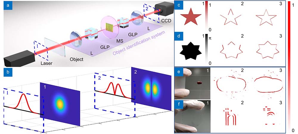
    Fig. 2. Experimental demonstration of object identification ability. (a) Schematic diagram of the experimental optical path for object identification. L: lens; GLP: Glan laser polarizer; MS: the optical computing metasurface; CCD: charge-coupled device. Two lenses with focal lengths of 175 mm form a 4f system. He-Ne laser beam with wavelength λ = 632.8 nm is chosen as the experimental laser source. (b) The theory intensity distribution in planes 1 and 2, respectively. (cd) Theoretical object identification results of high- and low-contrast objects. respectively. The first, second, and third rows represent the theoretical original, x-direction contours, and y-direction contours of those two types of objects, respectively. (ef) Part of experimental identification results of high- and low-contrast objects, respectively. The first, second, and third rows represent the experimental the ordinary images, as well as the contour surfaces along the x axis and y axis of two types of objects, respectively.
    Experimental demonstrations of an all-optical 3D high-contrast object reconstruction system. (a) Schematic diagram of the all-optical high-contrast object 3D reconstruction. Different color planes represent different projection planes. (b) Contour information results of an observed object on different projection planes in (a). (c) The 3D model reconstructed by recombining the different projection results captured in (b). (d1–d3) The origin image, the 3D experimental reconstruction models of rotation interval angle are 16° and 4° of coriander seed, respectively. (e1–f3) 3D experimental reconstruction models of the mushroom model and lollipop model with the same type as (d1–d3).
    Fig. 3. Experimental demonstrations of an all-optical 3D high-contrast object reconstruction system. (a) Schematic diagram of the all-optical high-contrast object 3D reconstruction. Different color planes represent different projection planes. (b) Contour information results of an observed object on different projection planes in (a). (c) The 3D model reconstructed by recombining the different projection results captured in (b). (d1d3) The origin image, the 3D experimental reconstruction models of rotation interval angle are 16° and 4° of coriander seed, respectively. (e1f3) 3D experimental reconstruction models of the mushroom model and lollipop model with the same type as (d1–d3).
    Experimental scheme of 3D reconstruction about the high-contrast object with complex surface. (a) The 3D reconstruction scheme relies on discretizing the target object into 2D slices with small gaps between them. (b) Contour information contained in every slice of an observed object would be captured. (c) The 3D model is reconstructed by recombining the different projection results captured in (b). (d–f) Original and 3D experimental reconstruction models of grooves, lands, and bosses, respectively. Scale bar, 200 μm.
    Fig. 4. Experimental scheme of 3D reconstruction about the high-contrast object with complex surface. (a) The 3D reconstruction scheme relies on discretizing the target object into 2D slices with small gaps between them. (b) Contour information contained in every slice of an observed object would be captured. (c) The 3D model is reconstructed by recombining the different projection results captured in (b). (df) Original and 3D experimental reconstruction models of grooves, lands, and bosses, respectively. Scale bar, 200 μm.
    Experimental results of all-optical 3D low-contrast object reconstruction system. (a1−a3) The images of the nonuniform contour images obtained by rotating the angle β, 0°, and −β of the second GLP, along the y direction, respectively. (a4) The phase gradient result is supplied by subtracting (a1) and (a3) along the y direction. (b1−b4) The intensity distributions of images (a1–a4) at black dashed line. The horizontal and vertical coordinates represent pixels and intensity, respectively. (c1−d4) The same results of (a1−b4) along the x direction. (e) The 3D experimental reconstruction model of the low-contrast object. (f) The SEM image of the partial sample surface. Scale bar, 50 μm. (g) The SEM image of the etching depth about the low-contrast object.
    Fig. 5. Experimental results of all-optical 3D low-contrast object reconstruction system. (a1a3) The images of the nonuniform contour images obtained by rotating the angle β, 0°, and −β of the second GLP, along the y direction, respectively. (a4) The phase gradient result is supplied by subtracting (a1) and (a3) along the y direction. (b1b4) The intensity distributions of images (a1–a4) at black dashed line. The horizontal and vertical coordinates represent pixels and intensity, respectively. (c1d4) The same results of (a1−b4) along the x direction. (e) The 3D experimental reconstruction model of the low-contrast object. (f) The SEM image of the partial sample surface. Scale bar, 50 μm. (g) The SEM image of the etching depth about the low-contrast object.
    Dingyu Xu, Wenhao Xu, Qiang Yang, Wenshuai Zhang, Shuangchun Wen, Hailu Luo. All-optical object identification and three-dimensional reconstruction based on optical computing metasurface[J]. Opto-Electronic Advances, 2023, 6(12): 230120
    Download Citation