• Opto-Electronic Advances
  • Vol. 6, Issue 12, 230120 (2023)
Dingyu Xu1, Wenhao Xu2, Qiang Yang1, Wenshuai Zhang1, Shuangchun Wen1, and Hailu Luo1、*
Author Affiliations
  • 1Laboratory for Spin Photonics, School of Physics and Electronics, Hunan University, Changsha 410082, China
  • 2School of Physics and Chemistry, Hunan First Normal University, Changsha 410205, China
  • show less
    DOI: 10.29026/oea.2023.230120 Cite this Article
    Dingyu Xu, Wenhao Xu, Qiang Yang, Wenshuai Zhang, Shuangchun Wen, Hailu Luo. All-optical object identification and three-dimensional reconstruction based on optical computing metasurface[J]. Opto-Electronic Advances, 2023, 6(12): 230120 Copy Citation Text show less

    Abstract

    Object identification and three-dimensional reconstruction techniques are always attractive research interests in machine vision, virtual reality, augmented reality, and biomedical engineering. Optical computing metasurface, as a two-dimensional artificial design component, has displayed the supernormal character of controlling phase, amplitude, polarization, and frequency distributions of the light beam, capable of performing mathematical operations on the input light field. Here, we propose and demonstrate an all-optical object identification technique based on optical computing metasurface, and apply it to 3D reconstruction. Unlike traditional mechanisms, this scheme reduces memory consumption in the processing of the contour surface extraction. The identification and reconstruction of experimental results from high-contrast and low-contrast objects agree well with the real objects. The exploration of the all-optical object identification and 3D reconstruction techniques provides potential applications of high efficiencies, low consumption, and compact systems.

    Introduction

    As object identification and three-dimensional (3D) reconstruction techniques become essential in various reverse engineering, artificial intelligence, medical diagnosis, and industrial production fields, there is an increasing focus on seeking vastly efficient, faster speed, and more integrated methods that can simplify processing1-6. In the current field of object recognition and 3D reconstruction, extracting sample contour information is primarily accomplished by various computer algorithms7, 8. While traditional computer processors suffer from multiple constraints, such as high power consumption, low-speed operation, and complex algorithms9, 10. In this regard, there has recently been growing attention in searching for alternative optical methods to perform those techniques. The development of optical theory and image processing has provided a more complete theoretical basis for object identification and 3D reconstruction techniques. Optical methods have received more attention as an alternative paradigm than traditional mechanisms in recent years due to their enormous advantages of ultra-fast operation speed, high integration, and low latency11-17.

    As two-dimensional nanostructures engineered at the subwavelength scales, metasurfaces have exhibited remarkable capabilities in the revolutionary developments in optics18-22, which can effectively simplify and deeply integrate the footprint of the optical systems. In practical applications, metasurfaces have shown the ability to efficiently manipulate several parameters of light, such as its phase23, 24 and polarization state25-27. As a result, metasurfaces are employed in numerous potential fields, such as optical analog computing12, 28-32, optical cryptography33-35, optical devices designing36, 37, signal manipulation38, 39, microscopy imaging40, optical imaging14, 41-44, and nanopainting45. Inspired by recently introduced optical analog computing and metasurface, we design and fabricate an optical computing metasurface that promotes development in imaging processing and 3D reconstruction. Different from the previous metasurface-based 3D imaging research4, 46, 47, this method relies on optical analog computing to obtain the counter information of objects and can achieve the object identification and 3D reconstruction of both high- contrast as well as low-contrast objects, which may provide an unique application of metasurface-based optical analog computing. In this regime, optical computing metasurface, as an artificial optical component, realizes the mathematical operations of the incident light fields by controlling a phase of the input electromagnetic field48.

    In this paper, we show that parts of the applications in the field of optical computing metasurface can be used in object identification and 3D reconstruction techniques for the purpose of establishing a faster, more convenient, and miniaturized processing system. In previous optical computing metasurface research, mainly achieved image edge detection31, 42, and few have extended it to object identification and 3D reconstruction. Our approach can be not only effective for high-contrast objects but also for low-contrast objects that are challenging to observe. Moreover, this system only relies on the contour information of the object to perform object identification and 3D reconstruction processing. Meanwhile, an optical computing metasurface for contour extraction can perform the task with high speed, low loss, and real-time. As a result, we demonstrate an experimental realization of all-optical object identification and 3D reconstruction based on the optical computing metasurface, including high-contrast and low-contrast objects. Due to the artificially designed subwavelength structures, this optical computing metasurface system can easily be integrated and miniaturized.

    Theory

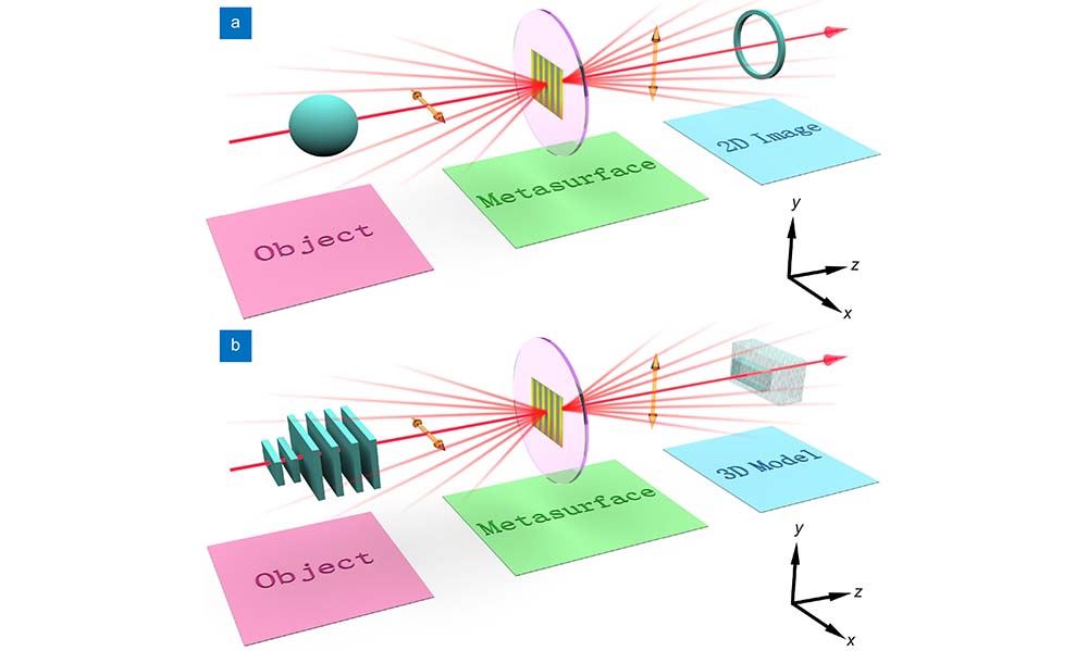
    The principle of the object identification system is schematically illustrated in Fig. 1(a). When the observed object is added to the system, the system can output the contour information about the object by way of the all-optical method, which has a high processing speed. This system not only has object identification ability but also can be extended to the all-optical 3D reconstruction technology. By recombining different projection images of the observed object, a 3D model of the observed object can be obtained, whether it is a high-contrast object or a low-contrast object [Fig. 1(b)]. Theoretically speaking, the 3D contour surface of a high-contrast object can be regarded as a superposition of infinite two-dimensional contours. Therefore, based on the object identification system, an all-optical 3D reconstruction scheme is proposed in this work. For low-contrast objects, a 3D reconstruction model can be acquired by breaking the orthogonal bias technique. The scheme details of the 3D reconstruction low-contrast object can be found in the Supplementary information.

    Scheme illustration of object identification and all-optical 3D reconstruction system. (a) A contour surface image of the object can be obtained in a single processing of the system. (b) High-contrast objects and low-contrast objects can be reconstructed by this all-optical computing metasurface system.

    Figure 1.Scheme illustration of object identification and all-optical 3D reconstruction system. (a) A contour surface image of the object can be obtained in a single processing of the system. (b) High-contrast objects and low-contrast objects can be reconstructed by this all-optical computing metasurface system.

    To begin with, we study the theoretical generation of this all-optical system. The experimental scheme of the object identification capability is displayed in Fig. 2(a). While the object is put into the light path, the input light beam irradiates the object and passes through the first Glan laser polarizer (GLP) to obtain a linearly polarized light, which can be simply written as

    Experimental demonstration of object identification ability. (a) Schematic diagram of the experimental optical path for object identification. L: lens; GLP: Glan laser polarizer; MS: the optical computing metasurface; CCD: charge-coupled device. Two lenses with focal lengths of 175 mm form a 4f system. He-Ne laser beam with wavelength λ = 632.8 nm is chosen as the experimental laser source. (b) The theory intensity distribution in planes 1 and 2, respectively. (c–d) Theoretical object identification results of high- and low-contrast objects. respectively. The first, second, and third rows represent the theoretical original, x-direction contours, and y-direction contours of those two types of objects, respectively. (e–f) Part of experimental identification results of high- and low-contrast objects, respectively. The first, second, and third rows represent the experimental the ordinary images, as well as the contour surfaces along the x axis and y axis of two types of objects, respectively.

    Figure 2.Experimental demonstration of object identification ability. (a) Schematic diagram of the experimental optical path for object identification. L: lens; GLP: Glan laser polarizer; MS: the optical computing metasurface; CCD: charge-coupled device. Two lenses with focal lengths of 175 mm form a 4f system. He-Ne laser beam with wavelength λ = 632.8 nm is chosen as the experimental laser source. (b) The theory intensity distribution in planes 1 and 2, respectively. (cd) Theoretical object identification results of high- and low-contrast objects. respectively. The first, second, and third rows represent the theoretical original, x-direction contours, and y-direction contours of those two types of objects, respectively. (ef) Part of experimental identification results of high- and low-contrast objects, respectively. The first, second, and third rows represent the experimental the ordinary images, as well as the contour surfaces along the x axis and y axis of two types of objects, respectively.

    E1(x,y)=Eip(x,y)[10],

    where Eip(x,y) represents the input optical field. Then the light beam carrying the information about the observed object directly passes through the optical computing metasurface. The Jones matrix of the optical computing metasurface can be expressed as49

    MJ=[cos2θsin2θsin2θcos2θ],

    where θ=πx/Γ refers to the optical axis angle of the metasurface, Γ is the period of the phase gradient along the x axis. Under the control of the spin Hall effect introduced by this optical computing metasurface, linearly polarized light will be converted into left- and right-circularly polarized light with the same displacements in opposite directions50-53. Thus, the optical field after the light beam hits the metasurface can be obtained (see the Section 1 of Supplemental information for calculations details)

    EopM=Eip(x+δx,y)[1i]+Eip(xδx,y)[1i],

    where [1±i]T/2 are the left- and right-circularly polarized light, respectively. δx=λf/Γ is the displacement introduced by the optical computing metasurface, λ is the wavelength of the light source, and f refers to the focal length of the lens in this expression. Eventually, to filter out the useless polarized light, the optical axis angle Ψ of the second GLP is rotated to be orthogonal to the optical axis of the first GLP. After the propagation through the second GLP, the final output field of the whole system can be given as

    Eop=[Eip(x+δx,y]Eip(xδx,y))[0i].

    Since the dimensions of objects are much more than the displacements δx in Eq. (4), Eop(x,y) can be approximately rewritten as

    Eop(x,y)iδxEip(x,y)x.

    According to Eq. (5), it can be found that the linearly polarized light formed by overlapping the left- and right-circularly polarized light is separated by the second GLP, leaving only the contour information of the object at a certain angle. By filtrating unnecessary polarization components, clearer images with enhanced contrast and resolution can be obtained.

    Except for high-contrast objects analyzed above, there are also low-contrast objects that are tough to recognize and reconstruct in real-life scenarios. These low-contrast objects are often difficult to observe directly due to their minuscule changes in intensity, making them almost invisible in bright fields. Thus, there is an urgent need to realize a fast and accurate technology to identify low-contrast objects. The expression of the low-contrast object can be considered as Eip(x,y)=exp[iϕ(x,y)], submitting it into Eq. (5), the output field of a low-contrast object can be obtained as

    Eop(x,y)=δxexp[iϕ(x,y])ϕ(x,y)x.

    This operation calculates the phase gradient of incident low-contrast objects, which can be employed for object identification. Since the complex characteristics of low-contrast objects and rotating them cannot attain the same 3D reconstruction model as high-contrast objects, we note that different phase delays generated by them would help us to reconstruct their 3D model. For this reason, we need to rely on the relationship between phase delays and thickness, this connection between the thickness and phase delays of the low-contrast object has been determined as the following

    ϕ=2πλ(ngna)d,

    where d refers to the distance traveled by the light beam when passing through the object, which is the thickness of the object. λ is the wavelength of the light beam, which used in this system is 632.8nm. ng,a are the refractive index of the glass substrate and air, respectively. This connection has not been previously employed in 3D reconstruction. According to Eq. (6) and the expression of Iop(x,y)=|Eop(x,y)|2, it can be known that the whole phase information, including signs and phase gradient, generated by low-contrast objects cannot be obtained through one contour image captured by a charge-coupled device (CCD) camera, because the signs of the phase cannot be determined. To solve this problem, breaking the orthogonal bias 3D reconstruction method has been employed to distinguish the different signs of the phase in this scheme. This method just needs to rotate the second GLP in Fig. 2(a) by a small angle β to break the state of orthogonal polarization with the first GLP, and the output light field of the whole system can be rewritten as

    Eop±β(x,y)=exp[iϕ(x,y])[δxcosβϕ(x,y]xsinβ).

    Subsequently, subtracting the results of the positive and negative rotation angles β can get the formula about the phase gradient (the specific details can be found in the Section 4 of the Supplemental information)

    p=Iop(x,y)δxsgn(|Eopβ(x,y|)2|Eopβ(x,y|)2).

    Results and discussion

    Experiment

    To experimentally achieve object identification, the whole identification system is the purple part in Fig. 2(a), which is only composed of four traditional optical components and an artificially designed metasurface. Two lenses are used to consist of a 4f system and their focal length are both 175 mm. The object is irradiated by the He-Ne laser beam with the wavelength of 632.8 nm, and the first GLP converts the input light carrying the information of this object to the horizontal linearly polarized light. The observed object and the metasurface are placed in front of and behind one focal length of the first lens, respectively, which equals 175 mm in this experiment. When light impacts the optical computing metasurface, the nanostructures of the metasurface would manipulate the polarization components contained in the light beam by changing the phase information of the light beam. The pure linearly polarized light image would transform into left- and right-circularly polarized light images with the same tiny shift δx but in opposite orientations. The overlapped parts of the image are incapable of passing through the second GLP whose optical axis is orthogonal to the first GLP. Ultimately, the single contour surface information of the object is recorded by a CCD camera which is set behind the focal length of the second lens in Fig. 2(a). When the input light beam in plane 1 passes through the whole optical system and reaches plane 2, its intensity distribution will change from one spot to two split spots in Fig. 2(b).

    Although the optical computing metasurface used in this system only can detect one-dimensional contours, the contour surface in another dimension can be able to extracted by rotating the optical computing metasurface along the direction perpendicular to the propagation direction of the light path. As the first example of object identification, we consider the high- and low-contrast objects theoretically in Fig. 2(c−d). Figure 2(c1−d3) exhibit the ordinary images, as well as the contour surfaces along the x axis and y axis of high- and low-contrast objects, respectively. The processed results by the whole system display the enhanced contour surfaces, which eliminate almost useless background data and significantly simplify the extraction process of contour surfaces. While one red bean and low-contrast object have been used to demonstrate object identification ability in experimentation, their results display that the system is experimentally feasible. To further verify the object identification capability of this system, we select a variety of high- and low-contrast objects for verification, including different kinds of objects and different individuals in the same kind. The detailed scheme and results can be found in Section 3 of the Supplemental information. This scheme is capable of identifying an object by the speed of light, which is critically significant for real-time object identification.

    As mentioned above, a 3D model of a high-contrast object can be reconstructed by continuously superimposing the two-dimensional contours. Therefore, to confirm the feasibility of the 3D reconstruction in the above scheme, take a sphere in Fig. 3(a) as an example. By rotating the object at equal intervals in the optical system, multiple contour results of the object on different projection planes can be captured by the CCD camera, as shown in Fig. 3(b). Finally, the 3D experimental reconstruction model of the high-contrast object can be reconstructed by rearranging and combining the whole contour information [Fig. 3(c)]. The fixed storage platform in Fig. 2(a) is replaced by a 360 continuous rotating platform (Thorlabs CR1) to produce those projection results about the high-contrast object on different planes in this experiment. The light source here is still the He-Ne laser beam with a wavelength of 632.8nm. The contour surfaces of the measured object at different rotation angles are captured by a CCD camera. These projection images reserve different features about the object, which helps reconstruct the corresponding 3D model. In the end, taking advantage of the computer program to rearrange the images of different angles, a 3D experimental reconstruction model that retains the contour surface information of the object can be obtained. In Fig. 3(d−e), coriander seed, mushroom model, and lollipop model have been used to demonstrate this reconstructed process. The second line in Fig. 3 is the original images of those three objects captured by a camera, as well as the third and the last lines in Fig. 3 represent the 3D experimental reconstruction model using the interval angles of 16° and 4°, respectively. It can be found that the contour information of the reconstructed model has already fitted well with the corresponding contour information of the real one even when the interval angles are relatively large. Theoretically speaking, the smaller the spacing angle, the more accurate the reconstructed model is. As proof-of-concept demonstrations, only using the limited contours to illustrate the feasibility of this scheme for 3D reconstruction, the experiment results demonstrate that this technique is facilitative and accurate.

    Experimental demonstrations of an all-optical 3D high-contrast object reconstruction system. (a) Schematic diagram of the all-optical high-contrast object 3D reconstruction. Different color planes represent different projection planes. (b) Contour information results of an observed object on different projection planes in (a). (c) The 3D model reconstructed by recombining the different projection results captured in (b). (d1–d3) The origin image, the 3D experimental reconstruction models of rotation interval angle are 16° and 4° of coriander seed, respectively. (e1–f3) 3D experimental reconstruction models of the mushroom model and lollipop model with the same type as (d1–d3).

    Figure 3.Experimental demonstrations of an all-optical 3D high-contrast object reconstruction system. (a) Schematic diagram of the all-optical high-contrast object 3D reconstruction. Different color planes represent different projection planes. (b) Contour information results of an observed object on different projection planes in (a). (c) The 3D model reconstructed by recombining the different projection results captured in (b). (d1d3) The origin image, the 3D experimental reconstruction models of rotation interval angle are 16° and 4° of coriander seed, respectively. (e1f3) 3D experimental reconstruction models of the mushroom model and lollipop model with the same type as (d1–d3).

    Without loss of generality, we also focus on high-contrast objects with complex contour surfaces. For some high-contrast objects with complex surfaces, the 3D reconstruction method by rotating objects is no longer applicable. Therefore, we propose another 3D reconstruction method by slicing objects. The process is also implementable with our platform because its 3D experimental reconstruction model can be reconstructed by superimposing those results of slices in different planes. Taking a sphere in Fig. 4(a) as an example, objects are sliced at tiny intervals, and multiple contour results of the object on different projection planes can be captured by a CCD camera, as shown in Fig. 4(b). Finally, the 3D experimental reconstruction model of the high-contrast object can be reconstructed by rearranging and combining the whole contour information [Fig. 4(c)]. Theoretically, the higher the precision of the slicing process, the more accurate the reconstructed 3D model will be. As proof-of-concept demonstrations, some simple geometries with distinct features, such as groove, land, and boss have been used to verify this experiment in Fig. 4(d1–f1). By slicing these three objects to obtain their contour information on different planes, rearranging and combining those contour information, and finally obtaining the 3D experimental reconstruction model about them in Fig. 4(d2–f2). Whether it's a groove with a notch on the inside, a raised boss on the outside, or a beveled land, the shapes and sizes of 3D experimental reconstruction models are in good agreement with the original objects. This method has potential application for the 3D reconstruction of objects with complex surfaces or complex internal structures.

    Experimental scheme of 3D reconstruction about the high-contrast object with complex surface. (a) The 3D reconstruction scheme relies on discretizing the target object into 2D slices with small gaps between them. (b) Contour information contained in every slice of an observed object would be captured. (c) The 3D model is reconstructed by recombining the different projection results captured in (b). (d–f) Original and 3D experimental reconstruction models of grooves, lands, and bosses, respectively. Scale bar, 200 μm.

    Figure 4.Experimental scheme of 3D reconstruction about the high-contrast object with complex surface. (a) The 3D reconstruction scheme relies on discretizing the target object into 2D slices with small gaps between them. (b) Contour information contained in every slice of an observed object would be captured. (c) The 3D model is reconstructed by recombining the different projection results captured in (b). (df) Original and 3D experimental reconstruction models of grooves, lands, and bosses, respectively. Scale bar, 200 μm.

    To demonstrate the performance of this technique in the 3D reconstruction field, for the second example, we considered 3D reconstruction of low-contrast objects. Owing to the unique characteristics of low-contrast objects, such as their lack of distinct boundaries and subtle variations in color and texture, the process of 3D reconstructing them is considerably intricate and challenging in comparison to high-contrast objects. In contrast to high-contrast objects that can be easily captured using the aforementioned technique of object rotation, an alternative method is required for determining thickness in the 3D reconstruction of low-contrast objects. In this regard, we propose a phase-related technology for reconstructing such objects and have successfully demonstrated its efficacy through experimentation. To realize this technology, we need to place the low-contrast object at the front focal length of the first lens in Fig. 2(a), and then obtain a uniform contour result of the low-contrast object by rotating the second GLP close to the CCD camera to an orthogonal state for the first GLP. Then, taking the orthogonal state as the benchmark, the optical axis of the second GLP is rotated clockwise and counterclockwise by an angle β to obtain two nonuniform contour results that break the orthogonal bias state, here we chose β as 1°, the relevant experimental results captured by a CCD camera are shown in Fig. 5(a1) and Fig. 5(a3), respectively. Subsequently, subtracting the two images then acquires a result [Fig. 5(a4)] that includes the sign information of phase gradient indicated in Eq. (9). Taking advantage of the contour intensity distribution under orthogonal bias in Fig. 5(a2), one-dimensional phase information can be obtained. The intensity curves obtained along the vertical black dashed lines in the low-contrast image of Fig. 5(a1–a4) are given in Fig. 5(b1–b4). Another dimension phase information can be afforded by rotating the optical computing metasurface, which is manifested in Fig. 5(c1–c4). The corresponding horizontal intensity curves of the low-contrast image are in Fig. 5(d1–d4). Finally, by processing the results of the phase gradient images in two vertical dimensions in Fi. 5(a4) and Fig. 5(d4), the 3D reconstruction of low-contrast objects has been realized successfully. The 3D experimental reconstruction model is shown in Fig. 5(e), the thickness of it is approximately 240nm. As indicated by Fig. 5(f–g), the SEM images of some samples show the sample surface and the writing depth, respectively. Different writing depths can provide various phase retardation, Fig. 5(g) exhibits that the writing depth of the prepared low-contrast object sample is approximately about 217nm, which demonstrates that the 3D reconstruction model of low-contrast in the experimental is in good agreement with the prepared one (the specific details can be found in the Section 4 of the Supplemental information).

    Experimental results of all-optical 3D low-contrast object reconstruction system. (a1−a3) The images of the nonuniform contour images obtained by rotating the angle β, 0°, and −β of the second GLP, along the y direction, respectively. (a4) The phase gradient result is supplied by subtracting (a1) and (a3) along the y direction. (b1−b4) The intensity distributions of images (a1–a4) at black dashed line. The horizontal and vertical coordinates represent pixels and intensity, respectively. (c1−d4) The same results of (a1−b4) along the x direction. (e) The 3D experimental reconstruction model of the low-contrast object. (f) The SEM image of the partial sample surface. Scale bar, 50 μm. (g) The SEM image of the etching depth about the low-contrast object.

    Figure 5.Experimental results of all-optical 3D low-contrast object reconstruction system. (a1a3) The images of the nonuniform contour images obtained by rotating the angle β, 0°, and −β of the second GLP, along the y direction, respectively. (a4) The phase gradient result is supplied by subtracting (a1) and (a3) along the y direction. (b1b4) The intensity distributions of images (a1–a4) at black dashed line. The horizontal and vertical coordinates represent pixels and intensity, respectively. (c1d4) The same results of (a1−b4) along the x direction. (e) The 3D experimental reconstruction model of the low-contrast object. (f) The SEM image of the partial sample surface. Scale bar, 50 μm. (g) The SEM image of the etching depth about the low-contrast object.

    Fabrication of optical computing metasurface and low-contrast objects

    The manufacture of the optical computing metasurface is fabricated by writing strip-like nanostructure at 200 μm below the surface of a silica glass sample by focusing the femtosecond pulse laser beam. After being irradiated by the femtosecond pulse laser beam, the uniform silica glass sample (SiO2) would decompose into the porous glass [SiO(22x)+xO2]. The intensity of the irradiated pulse laser beam can control the refractive index. Consequently, the modulation of the refractive index can be accomplished by periodically varying the intensity of the irradiated laser beam, and achieving periodic control of generating the strip-like nanostructures. The local directions of the optical computing metasurface are vertical and parallel to the nanostructures, respectively. The optical computing metasurface can be considered as a half-wave plate with homogeneous phase retardation because the characteristic dimension of the optical computing metasurfaces nanostructures is much smaller than the wavelength, the details can be found in the Section 2 of the Supplemental information. The low-contrast object samples used in this work have been prepared by the photolithography method, some pattern has been etched on the 500 μm-thickness, 50 mm-diameter nearly circle glass substrate, and then the remaining substrate is applied with SiO2. The etching area is approximately about 33 mm × 33 mm.

    Conclusions

    In conclusion, we have established a mechanism for all-optical object identification based on the optical computing metasurface as well as a 3D reconstruction technique. Utilization of this scheme, we experimentally demonstrated that the system could not only identify diverse sample information but also pick up defective products in the same type of objects, whether in high-contrast objects or low-contrast objects. This operation significantly improves the identification speed and reduces the memory consumption in the process. Our findings hold great promise for future applications in fields such as medical imaging and industrial inspection. Furthermore, we exploit this feature to reconstruct the model of the high-contrast samples with a complex outline by rotating samples, and to reconstruct low-contrast sample models that are difficult to observe by breaking orthogonal bias. Whether in biomedicine or manufacturing, a complete 3D reconstruction simulated model can quickly realize the simulation analysis of the samples. We anticipate that the exploitation of this proposed all-optical processing technology can bring novel opportunities for more efficient, convenient, and reliable object recognition as well as 3D model reconstruction. We believe that this work will pave the way for breakthroughs in imaging processing and industrial inspection areas and drive innovation across a wide range of 3D reconstruction industries.

    References

    [1] S Rusinkiewicz, O Hall-Holt, M Levoy. Real-time 3D model acquisition. ACM Trans Graphics, 438-446(2002).

    [3] S Zhang. High-speed 3D shape measurement with structured light methods: a review. Opt Lasers Eng, 119-131(2018).

    [4] G Kim, Y Kim, J Yun, SW Moon, S Kim et al. Metasurface-driven full-space structured light for three-dimensional imaging. Nat Commun, 5920(2022).

    [5] JW Liu, Q Yang, SZ Chen, ZC Xiao, SC Wen et al. Intrinsic optical spatial differentiation enabled quantum dark-field microscopy. Phys Rev Lett, 193601(2022).

    [6] WT Buono, A Forbes. Nonlinear optics with structured light. Opto-Electron Adv, 210174(2022).

    [7] R Gordon, GT Herman. Three-dimensional reconstruction from projections: a review of algorithms. Int Rev Cytol, 111-151(1974).

    [8] O Russakovsky, J Deng, H Su, J Krause, S Satheesh et al. ImageNet large scale visual recognition challenge. Int J Comput Vis, 211-252(2015).

    [9] H Kwon, D Sounas, A Cordaro, A Polman, A Alù. Nonlocal metasurfaces for optical signal processing. Phys Rev Lett, 173004(2018).

    [10] JX Zhou, HL Qian, CF Chen, JX Zhao, GR Li et al. Optical edge detection based on high-efficiency dielectric metasurface. Proc Natl Acad Sci U S A, 11137-11140(2019).

    [11] HJ Caulfield, S Dolev. Why future supercomputing requires optics. Nat Photonics, 261-263(2010).

    [12] A Silva, F Monticone, G Castaldi, V Galdi, A Alù et al. Performing mathematical operations with metamaterials. Science, 160-163(2014).

    [13] WL Liu, M Li, RS Guzzon, EJ Norberg, JS Parker et al. A fully reconfigurable photonic integrated signal processor. Nat Photonics, 190-195(2016).

    [14] Y Zhou, HY Zheng, II Kravchenko, J Valentine. Flat optics for image differentiation. Nat Photonics, 316-323(2020).

    [15] T Badloe, S Lee, J Rho. Computation at the speed of light: metamaterials for all-optical calculations and neural networks. Adv Photonics, 064002(2022).

    [16] X Zhang, LL Huang, RZ Zhao, HQ Zhou, X Li et al. Basis function approach for diffractive pattern generation with Dammann vortex metasurfaces. Sci Adv, eabp8073(2022).

    [17] LM Wu, TJ Fan, SR Wei, YJ Xu, Y Zhang et al. All-optical logic devices based on black arsenic–phosphorus with strong nonlinear optical response and high stability. Opto-Electron Adv, 200046(2022).

    [18] AV Kildishev, A Boltasseva, VM Shalaev. Planar photonics with metasurfaces. Science, 1232009(2013).

    [19] DY Xu, SC Wen, HL Luo. Metasurface-based optical analog computing: from fundamentals to applications. Adv Devices Instrum, 0002(2022).

    [20] YX Zhang, MB Pu, JJ Jin, XJ Lu, YH Guo et al. Crosstalk-free achromatic full Stokes imaging polarimetry metasurface enabled by polarization-dependent phase optimization. Opto-Electron Adv, 220058(2022).

    [21] YY Shi, CW Wan, CJ Dai, S Wan, Y Liu et al. On-chip meta-optics for semi-transparent screen display in sync with AR projection. Optica, 670-676(2022).

    [22] T Pertsch, SM Xiao, A Majumdar, GX Li. Optical metasurfaces: fundamentals and applications. Photonics Res, OMFA1-OMFA3(2023).

    [23] JX Zhou, HL Qian, JX Zhao, M Tang, QY Wu et al. Two-dimensional optical spatial differentiation and high-contrast imaging. Natl Sci Rev, nwaa176(2021).

    [24] YL Wang, QB Fan, T Xu. Design of high efficiency achromatic metalens with large operation bandwidth using bilayer architecture. Opto-Electron Adv, 200008(200008).

    [25] A Pors, MG Nielsen, SI Bozhevolnyi. Analog computing using reflective plasmonic metasurfaces. Nano Lett, 791-797(2015).

    [26] SJ Wang, WT Qin, S Zhang, YC Lou, CQ Liu et al. Nanoengineered spintronic-metasurface terahertz emitters enable beam steering and full polarization control. Nano Lett, 10111-10119(2022).

    [27] YJ Huang, TX Xiao, S Chen, ZW Xie, J Zheng et al. All-optical controlled-NOT logic gate achieving directional asymmetric transmission based on metasurface doublet. Opto-Electron Adv, 220073(2023).

    [28] TF Zhu, YH Zhou, YJ Lou, H Ye, M Qiu et al. Plasmonic computing of spatial differentiation. Nat Commun, 15391(2017).

    [29] Y Zhou, WH Wu, R Chen, WJ Chen, RP Chen et al. Analog optical spatial differentiators based on dielectric metasurfaces. Adv Opt Mater, 1901523(2020).

    [30] Q He, F Zhang, MB Pu, XL Ma, X Li et al. Monolithic metasurface spatial differentiator enabled by asymmetric photonic spin-orbit interactions. Nanophotonics, 741-748(2020).

    [31] DY Xu, H Yang, WH Xu, WS Zhang, KM Zeng et al. Inverse design of Pancharatnam–Berry phase metasurfaces for all-optical image edge detection. Appl Phys Lett, 241101(2022).

    [32] X Liang, Z Zhou, ZL Li, JX Li, C Peng et al. All-optical multiplexed meta-differentiator for tri-mode surface morphology observation. Adv Mater, 2301505(2023).

    [33] ZL Deng, QA Tu, YJ Wang, ZQ Wang, T Shi et al. Vectorial compound metapixels for arbitrary nonorthogonal polarization steganography. Adv Mater, 2103472(2021).

    [34] H Yang, K Ou, HY Wan, YQ Hu, ZY Wei et al. Metasurface-empowered optical cryptography. Mater Today, 424-445(2023).

    [35] F Zhang, YH Guo, MB Pu, LW Chen, MF Xu et al. Meta-optics empowered vector visual cryptography for high security and rapid decryption. Nat Commun, 1946(2023).

    [36] MB Pu, X Li, XL Ma, YQ Wang, ZY Zhao et al. Catenary optics for achromatic generation of perfect optical angular momentum. Sci Adv, e1500396(2015).

    [37] XG Luo, MB Pu, X Li, XL Ma. Broadband spin Hall effect of light in single nanoapertures. Light Sci Appl, e16276(2017).

    [38] Y Liu, MC Huang, QK Chen, DG Zhang. Single planar photonic chip with tailored angular transmission for multiple-order analog spatial differentiator. Nat Commun, 7944(2022).

    [39] C Zeng, H Lu, D Mao, YQ Du, H Hua et al. Graphene-empowered dynamic metasurfaces and metadevices. Opto-Electron Adv, 200098(2022).

    [40] XW Wang, H Wang, JL Wang, XS Liu, HJ Hao et al. Single-shot isotropic differential interference contrast microscopy. Nat Commun, 2063(2023).

    [41] XM Zhang, Y Zhou, HY Zheng, AE Linares, FC Ugwu et al. Reconfigurable metasurface for image processing. Nano Lett, 8715-8722(2021).

    [42] TT Xiao, H Yang, Q Yang, DY Xu, RS Wang et al. Realization of tunable edge-enhanced images based on computing metasurfaces. Opt Lett, 925-928(2022).

    [43] WW Fu, D Zhao, ZQ Li, SD Liu, C Tian et al. Ultracompact meta-imagers for arbitrary all-optical convolution. Light Sci Appl, 62(2022).

    [44] ZC Shen, F Zhao, CQ Jin, S Wang, LC Cao et al. Monocular metasurface camera for passive single-shot 4D imaging. Nat Commun, 1035(2023).

    [45] MW Song, L Feng, PC Huo, MZ Liu, CY Huang et al. Versatile full-colour nanopainting enabled by a pixelated plasmonic metasurface. Nat Nanotechnol, 71-78(2023).

    [46] XL Jing, RZ Zhao, X Li, Q Jiang, CZ Li et al. Single-shot 3D imaging with point cloud projection based on metadevice. Nat Commun, 7842(2022).

    [47] XL Jing, Y Li, JJ Li, YT Wang, LL Huang. Active 3D positioning and imaging modulated by single fringe projection with compact metasurface device. Nanophotonics, 1923-1930(2023).

    [48] SS He, RS Wang, HL Luo. Computing metasurfaces for all-optical image processing: a brief review. Nanophotonics, 1083-1108(2022).

    [49] Z Bomzon, G Biener, V Kleiner, E Hasman. Space-variant Pancharatnam–Berry phase optical elements with computer-generated subwavelength gratings. Opt Lett, 1141-1143(2002).

    [50] X Yin, Z Ye, J Rho, Y Wang, X Zhang. Photonic spin Hall effect at metasurfaces. Science, 1405-1407(2013).

    [51] XH Ling, XX Zhou, XN Yi, WX Shu, YC Liu et al. Giant photonic spin Hall effect in momentum space in a structured metamaterial with spatially varying birefringence. Light Sci Appl, e290(2015).

    [52] L Peng, H Ren, YC Liu, TW Lan, KW Xu et al. Spin Hall effect of transversely spinning light. Sci Adv, eabo6033(2022).

    [53] SQ Liu, SZ Chen, SC Wen, HL Luo. Photonic spin Hall effect: fundamentals and emergent applications. Opto-Electron Sci, 220007(2022).

    Dingyu Xu, Wenhao Xu, Qiang Yang, Wenshuai Zhang, Shuangchun Wen, Hailu Luo. All-optical object identification and three-dimensional reconstruction based on optical computing metasurface[J]. Opto-Electronic Advances, 2023, 6(12): 230120
    Download Citation