
Chonglei Zhang, Dongfang Zhang, Zhouping Bian. Dynamic full-color digital holographic 3D display on single DMD[J]. Opto-Electronic Advances, 2021, 4(3): 200049-1
- Opto-Electronic Advances
- Vol. 4, Issue 3, 200049-1 (2021)
Abstract
Introduction
Since iPhoneX announced 3D face recognition in a high profile, the acquisition and display of 3D data arouses everyone’s enthusiasm again. Holography is the only technique that can reproduce all the depth cues in the human visual system, and holographic 3D images are free from the visual fatigue caused by the vergence accommodation conflict that occurs in most conventional 3D displays, so holography is the most promising technology for realizing 3D visualization
In this study, we present a digital holographic technology based on a single DMD for full spatial complex field and wavelength control of a light beam that is used for a dynamic color holographic display. We adopt a spatial detour phase based on a DMD that combines the square regions of 16 adjacent DMD micro-mirrors to act as a modulation unit called a super-pixel to modulate the amplitude and the phase of the target field independently. Gray-scale images are realized by loading an amplitude mask, while color separation is realized by loading different direction-blazed gratings that are phase attached to a phase mask, then the amplitude mask and phase mask are combined to realize “color super-pixel” holography. A double-lens conjugate optical system is combined with a spatial filter in the spatial spectrum plane to realize reconstructed color images, effectively eliminating horizontal and vertical color difference while retaining the high resolution and very high switch speed.
Full-color super-pixels methods
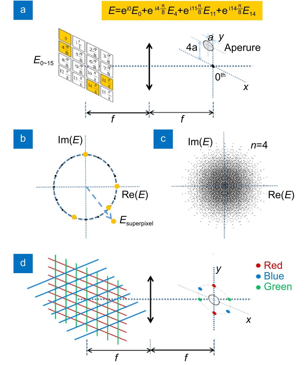
In the super-pixel method, K(N×N) neighboring pixels are combined into one super-pixel, and these pixels are denoted by E0, E1, ···, Ek−1, for a super-pixel with E, such that
![]()
Figure 1.
In attempts to resolve the interference of the zero-order light, higher diffraction orders of light and the higher diffraction-based reconstructed image that corresponds to the hologram caused by the SLM pixel structure on holographic reconstruction, most current research in holographic projection applications is based on filtering methods. Therefore, a spatial filter in the form of a circular aperture is placed in the Fourier plane of the DMD modulation plane. The spatial filter blocks the higher spatial frequencies so that the individual DMD pixels cannot be resolved and only the response of the super-pixel can be resolved. The size of the circular aperture acting as the spatial filter is set with an upper limit such that the highest allowed spatial frequency is no higher than
Because the red-green-blue (RGB) color mode is used as a type of color standard in industry, by varying and overlapping the three color channels of red (R), green (G), and blue (B), we can obtain all the colors that can be perceived by human vision. The amplitude mask is directly loaded with the gray intensity image of the three RGB colors, while the phase image is loaded with gratings in different directions with their different RGB components decomposed, as illustrated in Fig. 1(d). After the displacement grating is loaded, the different RGB components move into the corresponding directions of the displacement grating, which then filters out the spectrum of the RGB components and combines them in the double-lens conjugate imaging system to form the reconstructed color image. Because the double-lens conjugate imaging system guarantees conjugate imaging of the coding plane and the display plane, matching of the different colors can be achieved by selecting the appropriate achromatic lens. In this way, the gray information of the reconstructed color image appears fuller and clearer.
We verified the fidelity of the color super-pixel holography method using the experimental setup shown in Fig. 3. The super-pixel-based phase and amplitude modulation method can be set up for any wavelength, so it is highly suitable for color projection applications. While any light wavelength can be used to illuminate the DMD when using the super-pixel method, a wider wavelength range causes more modulation errors to occur because a phase gradient will be induced in DMD chips containing approximately 1280 pixels. And only by controlling the
Our DMD (DLP Discovery 4100, 1920 pixels ×1280 pixels, 9 kHz modulation frequency) with its pixel pitch of 13.69 µm is divided into super-pixels composed of 4×4 micro-mirrors. The hologram is calculated using MATLAB software and is then loaded into the DMD projection display. We decompose one three-color image into the RGB color mode with three single gray images. As shown in Fig. 2, the amplitude mask is the superposition of each color’s gray level, while the phase mask is the superposition of each color’s displacement grating phase.
![]()
Figure 2.
The amplitude and phase of each super-pixel must be obtained using a lookup table that contains a sufficient number of points from the complex plane with super-pixel modulation. The lookup table size is selected to be 855×855 points, which is approximately 15 times the number of fields that we can construct at 49291 for the super-pixel size n = 4. Use of a lookup table means that the calculations required to determine which DMD pixels are to be turned on are minimized and thus the performance is optimized. In our implementation, it takes less than 4 MB of memory to store the required table. Loading of the table and using it to look up a DMD pattern is completed within a fraction of a second.
A spatial filter in the form of a circular aperture is placed in the Fourier plane between the lenses. This spatial filter blocks the higher spatial frequencies so that the individual DMD pixels cannot be resolved and only the response of the super-pixel is resolved. The super-pixel’s 1st diffraction order is chosen as (
The RGB components of the different colors are then combined in a double-lens conjugate imaging system to form a reproduction color image with different gray color information, as illustrated in Fig. 3. The lenses are placed slightly off-axis with respect to each other, which results in an extra phase factor occurring in the target plane. The constructed field is measured in the target plane on a CCD (Thorlabs DCU224C, 1280×1024) camera by off-axis digital holography. The control part of the whole system is realized using computer control software, and the DMD as well as the CCD are connected to the computer through USB interfaces.
![]()
Figure 3.
Results
During the course of this experiment, we initially used red and green colors to complete the experiment, and used the logo of our unit as an experimental sample. As shown in Fig. 4(a1), we used red and green to fill in the logo, and the two colors were strictly separated. Figure 4(a2) shows a hologram loaded on the DMD. Using of local amplification shows that the hologram is an approximately linear grating that is limited by single color modulation. Figure 4(a3) shows the spectrum plane image, where use of different color filter holes allows different colors to be displayed. Figures 4(a4) and 4(a5) show the red and green parts, respectively, as independent parts of the final two-color holographic display image, which is shown in Fig. 4(a6). Figure 4(b1) shows red, green, yellow and orange four-color holographic display results, where yellow and orange are achieved by superimposing red and green. The local magnification of the spectrum plane is shown in Fig. 4(b2), which presents a more complex two-dimensional grating distribution. Figures 4(b4) and 4(b5) also show the red and green parts, respectively. Because the proportion of red in orange is higher than that of yellow, it is obvious that the intensity of the orange part is weaker than that of the corresponding yellow part shown in Fig. 4(b5). Figure 4(b6) shows the final image result, where the four-color holographic display is well realized.
![]()
Figure 4.
We have also achieved a tri-color holographic display image, as shown in Fig. 5. Figure 5(a2) shows the spectrum plane image; use of the different color89 filter holes allows different colors to be displayed. Figures 5(b2), 5(b3), and 5(b4) also show the red, green and blue images separately; pink and yellow are produced by superposition of the three primary colors, as shown in the corresponding part. Figures 5(a3) and 5(b5) show the final result images, indicating that the three-color and six-color holographic displays were well realized. We have also realized imaging of natural pictures with more detailed images and more image layers, as shown in Figs. 5(c1) and 5(c2). Because of the influence of the pixel resolution, there will be some crosstalk within the rich color details of the image.
![]()
Figure 5.
To verify the reliability of this method, the original image (size of 1920 pixels ×1280 pixels) and the experimental image (size of 1280 pixels ×1024 pixels) are compared to verify the correctness of the method. In general, the verification criteria are the similarity of the image structure and the color. The algorithm used to verify the structural similarity is the Hash method
| Structural
| Color similarity
| Color similarity
| |
| 0.9397 | 0.43278 | 0.9981 | |
| 0.9611 | 0.49773 | 0.9973 | |
| 0.9606 | 0.46102 | 0.9913 | |
| 0.9328 | 0.67102 | 0.9923 | |
| 0.8896 | 0.58549 | 0.9832 |
Table 1. Evaluation of experimental and design images
To verify the color similarity, we adopted two algorithms, where one was an objective algorithm and the other was a subjective algorithm. The main reason for this approach is that human beings have a strong ability to recognize structures, so the subjective algorithm is closer to the human visual cognition process. We adopted a histogram color similarity algorithm that was considered to be an objective algorithm
For traditional digital holographic 3D display, sizes of reconstructed objects and viewing angles are much smaller. Therefore, most of the reported digital holographic 3D displays are shown with static and simple structure samples. The combinatorial product of sizes of reconstructed and viewing angles is known as space bandwidth product (SBP) and is determined by SLM pixel counts and switching speed
![]()
Figure 6.
Conclusions
We adopted the color super-pixel digital holographic technology to realize the dynamic full-color 3D display, which achieves measured structural similarity of more than 88% and color similarity of more than 98%, while retaining the high switch speed of 9 kHz. When compared with traditional spatial optical modulation based on liquid crystals, the color super-pixel digital holographic technology can not only realize complex amplitude modulation, but also improve the display speed by two orders of magnitude which greatly enlarge the SBP of digital holographic display. As the switching speed of DMD device is further increased and the pixel size is further reduced, the modulation efficiency and resolution of this technology can be further improved, and full-color digital holographic 3D display on single DMD would be more widely used.
References
[1] K Wakunami, PY Hsieh, R Oi, T Senoh, H Sasaki, et al. Projection-type see-through holographic three-dimensional display. Nat Commun, 7, 12954(2016).
[2] DM Hoffman, AR Girshick, K Akeley, MS Banks. Vergence-accommodation conflicts hinder visual performance and cause visual fatigue. J Vis, 8, 33(2008).
[3] K Szulzycki, V Savaryn, I Grulkowski. Generation of dynamic Bessel beams and dynamic bottle beams using acousto-optic effect. Opt Express, 24, 23977-23991(2016).
[4] P St-Hilaire, SA Benton, ME Lucente, PM Hubel. Color images with the MIT holographic video display. Proc SPIE, 1667, 73-84(1992).
[5] Y Sando, D Barada, T Yatagai. Full-color holographic 3D display with horizontal full viewing zone by spatiotemporal-division multiplexing. Appl Opt, 57, 7622-7626(2018).
[6] 11, 437–445(2003).
[7] AA Khalifa, HA Aly, AF El-Sherif. Active modulation of laser coded systems using near infrared video projection system based on digital micromirror device (DMD). Proc SPIE, 9761, 97610A(2016).
[8] LJ Hornbeck. The DMDTM projection display chip: a MEMS-based technology. MRS Bull, 26, 325-327(2001).
[9] XZ Sang, FC Fan, CC Jiang, S Choi, WH Dou, et al. Demonstration of a large-size real-time full-color three-dimensional display. Opt Lett, 34, 3803-3805(2009).
[10] SJ Xing, XZ Sang, XB Yu, C Duo, B Pang, et al. High-efficient computer-generated integral imaging based on the backward ray-tracing technique and optical reconstruction. Opt Express, 25, 330-338(2017).
[11] M Makowski, M Sypek, I Ducin, A Fajst, A Siemion, et al. Experimental evaluation of a full-color compact lensless holographic display. Opt Express, 17, 20840-20846(2009).
[12] M Makowski, I Ducin, M Sypek, A Siemion, A Siemion, et al. Color image projection based on Fourier holograms. Opt Lett, 35, 1227-1229(2010).
[13] K Kumagai, S Hasegawa, Y Hayasaki. Volumetric bubble display. Optica, 4, 298-302(2017).
[14] F Yaraş, H Kang, L Onural. Real-time phase-only color holographic video display system using LED illumination. Appl Opt, 48, H48-H53(2009).
[15] K Yamamoto, Y Ichihashi, T Senoh, R Oi, T Kurita. 3D objects enlargement technique using an optical system and multiple SLMs for electronic holography. Opt Express, 20, 21137-21144(2012).
[16] H Sasaki, K Yamamoto, K Wakunami, Y Ichihashi, R Oi, et al. Large size three-dimensional video by electronic holography using multiple spatial light modulators. Sci Rep, 4, 6177(2014).
[17] A Peña, MF Andersen. Complete polarization and phase control with a single spatial light modulator for the generation of complex light fields. Laser Phys, 28, 076201(2018).
[18] L Wu, SB Cheng, AH Tao. Simultaneous shaping of amplitude and phase of light in the entire output plane with a phase-only hologram. Sci Rep, 5, 15426(2015).
[19] S Reichelt, R Häussler, G Fütterer, N Leister, H Kato, et al. Full-range, complex spatial light modulator for real-time holography. Opt Lett, 37, 1955-1957(2012).
[20] SF Lin, D Wang, QH Wang, ES Kim. Full-color holographic 3D display system using off-axis color-multiplexed-hologram on single SLM. Opt Lasers Eng, 126, 105895(2020).
[21] E Ulusoy, L Onural, HM Ozaktas. Full-complex amplitude modulation with binary spatial light modulators. J Opt Soc Am A, 28, 2310-2321(2011).
[22] SA Goorden, J Bertolotti, AP Mosk. Superpixel-based spatial amplitude and phase modulation using a digital micromirror device. Opt Express, 22, 17999-18009(2014).
[23] Proceedings of 2000 International Conference on Image Processing (Cat. No.00CH37101) 664-666(IEEE, 2000); http://doi.org/10.1109/ICIP.2000.899541.
[24] MA Stricker, M Orengo. Similarity of color images. Proc SPIE, 2420, 381-393(1995).
[25] Z Wang, AC Bovik. A universal image quality index. IEEE Signal Process Lett, 9, 81-84(2002).
[26] Z Wang, A Bovik, HR Sheikh, EP Simoncelli. Image quality assessment: from error visibility to structural similarity. IEEE Trans Image Process, 13, 600-612(2004).
[27] Y Sando, D Barada, T Yatagai. Holographic 3D display observable for multiple simultaneous viewers from all horizontal directions by using a time division method. Opt Lett, 39, 5555-5557(2014).


Set citation alerts for the article
Please enter your email address

© Copyright 2018-2021 | Chinese Laser Press. All Rights Reserved 沪ICP备15018463号-20