
Yanxian Wei, Hailong Zhou, Yuntian Chen, Yunhong Ding, Jianji Dong, Xinliang Zhang. Anti-parity-time symmetry enabled on-chip chiral polarizer[J]. Photonics Research, 2022, 10(1): 76
- Photonics Research
- Vol. 10, Issue 1, 76 (2022)
Abstract
1. INTRODUCTION
Non-Hermitian systems, especially parity-time (PT) symmetric systems, have attracted widespread attention for their fascinating physical properties and broad applications. Fruitful advances have been achieved in the field of PT symmetry [1], such as unidirectional propagation and lasing [2–8], single-mode lasing [9–12], sense enhancement [13–18], and optoelectronics oscillators [19,20]. Notably, owing to the non-Hermiticity-induced nonadiabatic transitions, chiral mode switching was achieved for symmetric and antisymmetric modes by encircling the exceptional point (EP) in a PT symmetric system [21–29], exhibiting great potential for chiral devices [7,27,30]. However, different from the spatial modes, it is unsuitable to perform the encircling EP evolution in an on-chip PT symmetric system for chiral polarization switching, because the polarization modes are asymmetrical, and the coupling between two orthogonal polarization states needs not only the match of effective indexes of the two polarization modes but also the share of a common parallel polarization component between them. As a result, the chiral polarization switching to date has not been yielded. However, as a basic property of light, polarization has abundant applications, such as communication [31–33], imaging [34–36], and storage [37]. Thus, chiral polarization switching can inspire fascinating interest into handling polarization information.
As the counterpart of PT symmetric systems, anti-PT symmetric systems were first proposed by Ge and Türeci in 2013 [38], conjugated to those observed in PT-symmetric ones [39]. Many novel phenomena about anti-PT symmetry have been observed, e.g., sensing enhancement [40], coherent perfect absorption lasing [41], heat transfer [42], topological superconductors [43], and chiral dynamics [44]. Different from the PT symmetry, the eigenmodes of anti-PT symmetric systems are asymmetrical when the real parts of the corresponding eigenvalue split, which exactly matches the polarization mode characteristics. Anti-PT symmetry shows great potential in physics and applications. For practical optical applications, anti-PT symmetry has harsh requirements of pure imaginary coupling coefficients, which were demonstrated by indirectly dissipative coupling [45], nonlinear coupling [46], spinning the resonator [47], etc. Benefiting from these breakthroughs, anti-PT symmetry can be heralded as a powerful tool to design optical devices with fascinating properties. Notably, the indirect coupling in anti-PT symmetric systems makes it possible to construct chiral polarization switching.
In this paper, we propose and experimentally demonstrate a chiral polarizer based on an anti-PT symmetric system for the first time. Conventional polarizers operate by rejecting undesired polarization, and the transmission axes are the same for bidirectional propagation, whereas, our chiral polarizer operates by rotating the orthogonal polarization state to the transmission axis [48] and exhibits different transmission axes for forward and backward propagation. We induce a transitional mode between transverse electric (TE) and transverse magnetic (TM) modes and realize the encircling-an-EP parametric evolution in an integrated polarization-coupled anti-PT symmetric system. For arbitrary input polarization states, we achieve a polarization extinction ratio of 10 dB between the transmission of TE and TM modes over a bandwidth from 1550 to 1590 nm. Moreover, the application of polarization data formatting is also demonstrated by a communication experiment with a bit rate of 10 Gbit/s on-off keying signals. Our work demonstrates a practicable application for encircling EP in non-Hermitian systems and provides a novel tool for future polarization manipulating such as data formatting and polarization-multiplexing duplex communication.
Sign up for Photonics Research TOC. Get the latest issue of Photonics Research delivered right to you!Sign up now
2. RESULT
A. Principle of Chiral Polarization Switching
Figure 1(a) shows the comparison between a conventional polarizer and our chiral polarizer. The chiral polarizer exhibits different transmission axes for forward and backward propagation. In forward propagation, the output polarization state will be rotated to the vertical direction no matter what the input polarization states are. However, in backward propagation, the output polarization state will be rotated to the horizontal direction. This chiral dynamic can be used for on-chip polarization data formatting or polarization multiplexing duplex operation. It should be noted that a conventional polarizer operates by rejecting undesired polarization, and the transmission axes are the same for bidirectional propagation. Figure 1(b) illustrates the chip structure of the chiral polarizer, constructed with a three-waveguide coupled region and two polarization beam splitters (PBSs). The three-waveguide coupled region consists of three waveguides, WG1, WG2, and WG3, where WG1 and WG3 support and modes, respectively, and WG2 supports the transitional mode. The coupled region is a dual-port system, in which the and modes are processed separately. When light is injected from the left, the output mode is regardless of or injection, whereas, when light is injected from the right, the output mode is for both and injection. The PBS is used to decompose the input light into and modes and combine the output light to handle arbitrary polarization. The anti-PT symmetry is realized by the indirect dissipate coupling between WG1 and WG3. We use the coupled-mode theory to analyze the system. The model Hamiltonian takes the form
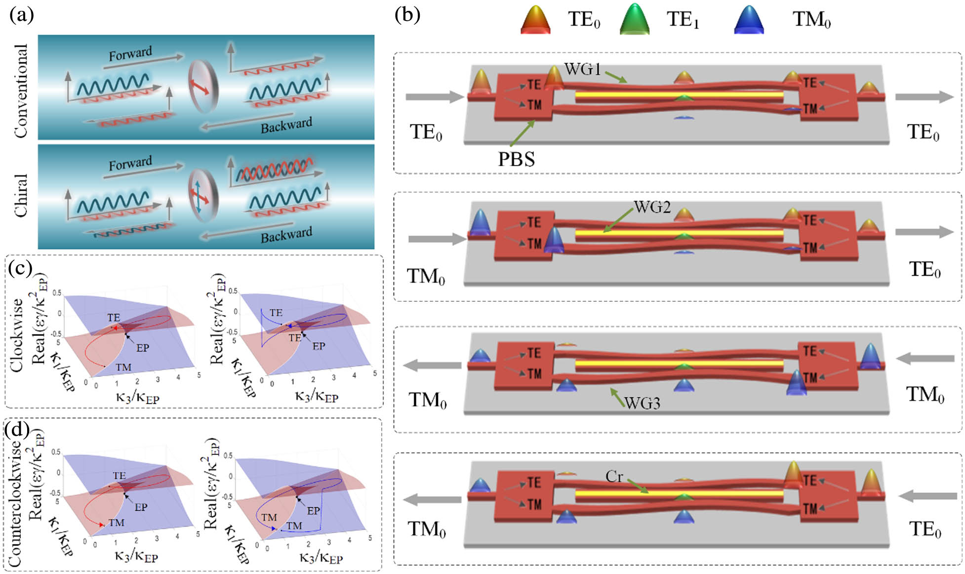
Figure 1.Concept and scheme of the chiral polarizer. (a) Comparison between conventional polarizer and our chiral polarizer. (b) Scheme of our chiral polarizer. The chiral polarizer is constructed with three waveguides WG1, WG2, and WG3; where WG1 and WG3 are supposed to be lossless, and WG2 has a high loss. (c) Encircling EP evolution clockwise. (d) Encircling EP evolution counterclockwise.
Figure 1(c) shows the process of the eigenvalue moving clockwise on the Reimann surface. In this direction, the mode moves on the loss surface. Due to the presence of absorption, the evolution of mode cannot maintain on the loss surface for the entire loop and hops to the gain surface during the evolution. As a result, the mode returns to itself without mode flipping. However, the mode moves on the gain surface, which indicates that the evolution of the mode can survive to the end without hopping and complete the mode flipping. Figure 1(d) demonstrates the evolution in counterclockwise direction. In contrast with the process in the clockwise direction, the mode moves on the loss surface, while the mode moves on the gain surface when encircling EP in the counterclockwise direction. Figures 1(c) and 1(d) indicate that the final polarization state of light for encircling EP clockwise is the mode and that for encircling EP counterclockwise is the mode, no matter the state of original polarization.
B. Design of the Chiral Polarizer
Figure 2 shows the design details of the proposed chiral polarizer. The device is designed on a silicon-on-insulator (SOI) platform with 250 nm top silicon and 2 μm buried oxide. We use the finite difference time domain method to calculate the mode field distribution and effective refractive index of each mode in waveguides with different widths, as shown in Fig. 2(a). In order to realize mode coupling, the effective refractive indexes of the three modes in respective waveguides must be approximately equal. On this premise, the widths of the waveguides are designed to be 315 nm for WG1, 441 nm for WG3, and 644 nm for WG2, which are marked by the dashed lines in Fig. 2(a). A Cr strip with a width of 100 nm and a thickness of 100 nm is deposited on the top of WG2 to induce the absorption loss ().
![]()
Figure 2.Detailed design of chiral polarizer. (a) Effective refractive index of each mode versus the width of waveguide. (b) Optimized gap transform function that generates encircling EP parametric evolution. (c) Wavelength-dependent parametric loops for the design shown in (a) and (b).
The coupling coefficients and can be controlled by changing the gaps between waveguides. Figure 2(b) shows the gap variation along the propagation direction between WG1 and WG2 (gap12) and that between WG2 and WG3 (gap23), which are given by
![]()
Figure 3.Simulation results of the chiral polarizer. (a) Simulation power distributions in the waveguides for forward and backward propagation. (b) Transmission spectra for different input.
C. Fabrication and Experiment
The device is fabricated by a standard electron-beam (e-beam) lithography-based nanofabrication process on the commercial 250 nm SOI platform. The scanning electron microscope (SEM) is used to determine the dimensions of the devices and confirm the obtained geometric shape, as shown in Fig. 4(a). The detailed structures of PBS and coupling region are presented as insets in Fig. 4(a) with the tested spectrum shown in Figs. 4(f) and 4(g); the fabrication of PBS is presented in the Appendix B [50]. The device is characterized by measuring the transmission spectra. The measured transmission spectra for and injection are shown in Figs. 4(b)–4(e). TE and TM denote the input or output mode from the left, and TE’ and TM’ denote the input or output mode from the right. Figures 4(b) and 4(c) demonstrate the output spectra for forward propagation. It can be seen clearly that the is the dominant output mode whichever or mode is inputted, whereas the mode becomes the dominant output mode for backward propagation, as shown in Figs. 4(d) and 4(e). The oscillations of the experimental spectra are due to the resonances between the facets of the coupling fiber. A 10 dB extinction ratio is achieved from 1550 to 1590 nm. The polarizer exhibits a loss of for input from the left and input from the right. This loss is the intrinsic property of encircling EP in a passive system, which can be reduced by shortening the coupling length. It is a trade-off between insertion loss and extinction ratio. For more practical applications, the coupling length should be designed carefully or induce gain to balance the loss. Compared with the simulation results, the experiment spectra are redshifted, which is mainly caused by fabrication errors. According to Fig. 2(a), the refractive indexes dependent on waveguide width in and modes have high slopes, which indicate that the fabrication errors may manifest a vital impact on the performance of device. In fact, we have tested different devices with gradually varied parameters. The asymmetric mode switching phenomenon can be observed when the deviation of the widths of waveguides is lower than 10 nm. The insertion loss is mainly influenced by the width of the Cr strip. A wider Cr strip leads to higher insertion loss. For a well-performed device, the fabrication error should be controlled within .
![]()
Figure 4.SEM images of the chip and the experimentally measured spectra. (a) SEM images of the proposed chiral polarizer. Zoom-in images of polarization beam splitter and coupled region are shown in the subgraphs. (b)–(e) Experimentally measured spectra of the device for the (b), (c) forward propagation and (d), (e) backward propagation. TE and TM denote the modes input or output from the left; TE’ and TM’ denote the modes input or output from the right. (f), (g) Test results of the PBS.
To further verify the practical communication performances of the proposed chiral polarizer, a communication experiment is demonstrated to perform a function of formatting the data encoded on polarization channels into a particular polarization state. The experiment setup is illustrated in Fig. 5(a). The on–off keying (OOK) data are encoded on the and modes, where the mode indicates “1” and mode indicates “0.” Without loss of generality, the polarization encoded signals can be decomposed into data loaded on the mode and its inverted data loaded on the mode. In the experiment, the 10 GHz random OOK data and its inverted data are generated by an arbitrary waveform generator and loaded on the and modes by intensity modulator (IM), respectively. An erbium-doped fiber amplifier is used to compensate the power difference between and modes induced by the chiral polarizer. Data streams loaded on and modes are combined by the PBS and injected into the chip. The output light is decomposed into and modes and received by the oscilloscope. The input waveforms for forward and backward propagation is shown in Figs. 5(b) and 5(d), respectively. The output and polarization components of light are shown in Figs. 5(c) and 5(e). According to the analysis above, the data stream loaded on different polarization states transporting forward will be formatted into the mode. It can be seen clearly in Fig. 5(c) that most signal power is transferred to the mode, while only a little signal power remains in the mode. However, the mode becomes the dominant mode when the data transports backward. Figure 5(e) shows that most signal power transferred to mode rather than mode, which indicates the function of polarization data formatting with our chiral polarizer. An extinction ratio of 13 and 14 dB for forward and backward propagation is achieved, respectively.
![]()
Figure 5.Experiment setup and results of communication experiment. (a) Experiment setup. (b) The 10 GHz OOK bits stream loaded on TE and TM modes for inputting forward. (c) Power summary of the output TE and TM modes. (d), (e) Result of inputting backward. TE and TM denote the input or output modes from the left; TE’ and TM’ denote the input or output modes from the right.
3. CONCLUSION
In summary, we have proposed a chiral polarizer in an anti-PT symmetric system, which forms different polarized states dependent on light propagation direction. Based on the indirect coupling property of the anti-PT symmetric system, we successfully build an on-chip polarization-coupled anti-PT symmetric system for the first time. With the encircling EP evolution, we implement the chiral asymmetry polarization switch and chiral polarizer. The proposed chiral polarizer has been successfully applied to polarization data formatting for polarization encoding signals. The extinction ratio between the and modes for forward and backward propagation is 13 and 14 dB, respectively. Our work provides a new on-chip polarization manipulation method and demonstrates a practicable application in optics for encircling EP in non-Hermitian systems.
Acknowledgment
Acknowledgment. We thank Prof. Chengwei Qiu from National University of Singapore for the fruitful discussions.
APPENDIX A: THEORY OF INDIRECT DISSIPATED COUPLING OF ANTI-PT SYMMETRIC SYSTEM
For the three-waveguide-coupled system shown in Fig.
In Eq. (
APPENDIX B: FABRICATION AND TEST RESULT OF ON-CHIP PBS
We use on-chip PBSs to split the input light into TE and TM modes and recombine the output light. The PBS is based on a directional coupler, which has a significantly larger coupling coefficient than the mode coupling coefficient. The coupling length is selected so that the mode achieves full coupling, while the mode remains negligible coupling. The PBS is fabricated by electron beam lithography (EBL) and inductively coupled plasma (ICP) etching. The insertion loss of the PBS for TE input is negligible and for TM input is about 1 dB; further, the extinction ratio is tested by TE and TM mode input, respectively. The extinction ratio is 35 dB for the TE mode input. For the TM mode input, the extinction ratio is 23 dB. The light splitting ability of PBS is enough for our chiral polarizer.
References
[1] S. K. Ozdemir, S. Rotter, F. Nori, L. Yang. Parity-time symmetry and exceptional points in photonics. Nat. Mater., 18, 783-798(2019).
[2] H. Ramezani, T. Kottos, R. El-Ganainy, D. N. Christodoulides. Unidirectional nonlinear PT-symmetric optical structures. Phys. Rev. A, 82, 043803(2010).
[3] L. Feng, M. Ayache, J. Huang, Y. L. Xu, M. H. Lu, Y. F. Chen, Y. Fainman, A. Scherer. Nonreciprocal light propagation in a silicon photonic circuit. Science, 333, 729-733(2011).
[4] Z. Lin, H. Ramezani, T. Eichelkraut, T. Kottos, H. Cao, D. N. Christodoulides. Unidirectional invisibility induced by PT-symmetric periodic structures. Phys. Rev. Lett., 106, 213901(2011).
[5] L. Feng, Y. L. Xu, W. S. Fegadolli, M. H. Lu, J. E. Oliveira, V. R. Almeida, Y. F. Chen, A. Scherer. Experimental demonstration of a unidirectional reflectionless parity-time metamaterial at optical frequencies. Nat. Mater., 12, 108-113(2013).
[6] L. Chang, X. Jiang, S. Hua, C. Yang, J. Wen, L. Jiang, G. Li, G. Wang, M. Xiao. Parity–time symmetry and variable optical isolation in active–passive-coupled microresonators. Nat. Photonics, 8, 524-529(2014).
[7] B. Peng, S. K. Ozdemir, M. Liertzer, W. Chen, J. Kramer, H. Yilmaz, J. Wiersig, S. Rotter, L. Yang. Chiral modes and directional lasing at exceptional points. Proc. Natl. Acad. Sci. USA, 113, 6845-6850(2016).
[8] Z. Chen, M. Segev. Highlighting photonics: looking into the next decade. eLight, 1, 2(2021).
[9] M. Brandstetter, M. Liertzer, C. Deutsch, P. Klang, J. Schoberl, H. E. Tureci, G. Strasser, K. Unterrainer, S. Rotter. Reversing the pump dependence of a laser at an exceptional point. Nat. Commun., 5, 4034(2014).
[10] L. Feng, Z. J. Wong, R. M. Ma, Y. Wang, X. Zhang. Single-mode laser by parity-time symmetry breaking. Science, 346, 972-975(2014).
[11] H. Hodaei, M. A. Miri, M. Heinrich, D. N. Christodoulides, M. Khajavikhan. Parity-time-symmetric microring lasers. Science, 346, 975-978(2014).
[12] B. Peng, S. K. Ozdemir, S. Rotter, H. Yilmaz, M. Liertzer, F. Monifi, C. M. Bender, F. Nori, L. Yang. Loss-induced suppression and revival of lasing. Science, 346, 328-332(2014).
[13] G. Demange, E.-M. Graefe. Signatures of three coalescing eigenfunctions. J. Phys. A, 45, 025303(2011).
[14] S. N. Jouybari. Refractive index measurement using coupled micro-resonator laser based on parity-time symmetry breaking. J. Mod. Opt., 63, 798-803(2015).
[15] P.-Y. Chen, J. Jung. PT symmetry and singularity-enhanced sensing based on photoexcited graphene metasurfaces. Phys. Rev. Appl., 5, 064018(2016).
[16] Z.-P. Liu, J. Zhang, Ş. K. Özdemir, B. Peng, H. Jing, X.-Y. Lü, C.-W. Li, L. Yang, F. Nori, Y.-X. Liu. Metrology with PT-symmetric cavities: enhanced sensitivity near the PT-phase transition. Phys. Rev. Lett., 117, 110802(2016).
[17] S. Zhang, Z. Yong, Y. Zhang, S. He. Parity-time symmetry breaking in coupled nanobeam cavities. Sci. Rep., 6, 24487(2016).
[18] H. Hodaei, A. U. Hassan, S. Wittek, H. Garcia-Gracia, R. El-Ganainy, D. N. Christodoulides, M. Khajavikhan. Enhanced sensitivity at higher-order exceptional points. Nature, 548, 187-191(2017).
[19] J. Zhang, L. Li, G. Wang, X. Feng, B.-O. Guan, J. Yao. Parity-time symmetry in wavelength space within a single spatial resonator. Nat. Commun., 11, 3217(2020).
[20] J. Zhang, J. Yao. Parity-time-symmetric optoelectronic oscillator. Sci. Adv., 4, eaar6782(2018).
[21] J. Doppler, A. A. Mailybaev, J. Bohm, U. Kuhl, A. Girschik, F. Libisch, T. J. Milburn, P. Rabl, N. Moiseyev, S. Rotter. Dynamically encircling an exceptional point for asymmetric mode switching. Nature, 537, 76-79(2016).
[22] H. Xu, D. Mason, L. Jiang, J. G. Harris. Topological energy transfer in an optomechanical system with exceptional points. Nature, 537, 80-83(2016).
[23] Y. Choi, C. Hahn, J. W. Yoon, S. H. Song, P. Berini. Extremely broadband, on-chip optical nonreciprocity enabled by mimicking nonlinear anti-adiabatic quantum jumps near exceptional points. Nat. Commun., 8, 14154(2017).
[24] J. W. Yoon, Y. Choi, C. Hahn, G. Kim, S. H. Song, K. Y. Yang, J. Y. Lee, Y. Kim, C. S. Lee, J. K. Shin, H. S. Lee, P. Berini. Time-asymmetric loop around an exceptional point over the full optical communications band. Nature, 562, 86-90(2018).
[25] X.-L. Zhang, S. Wang, B. Hou, C. T. Chan. Dynamically encircling exceptional points:
[26] X.-L. Zhang, J.-F. Song, C. T. Chan, H.-B. Sun. Distinct outcomes by dynamically encircling an exceptional point along homotopic loops. Phys. Rev. A, 99, 063831(2019).
[27] A. Li, J. Dong, J. Wang, Z. Cheng, J. S. Ho, D. Zhang, J. Wen, X.-L. Zhang, C. T. Chan, A. Alù, C.-W. Qiu, L. Chen. Hamiltonian hopping for efficient chiral mode switching in encircling exceptional points. Phys. Rev. Lett., 125, 187403(2020).
[28] Q. Liu, S. Li, B. Wang, S. Ke, C. Qin, K. Wang, W. Liu, D. Gao, P. Berini, P. Lu. Efficient mode transfer on a compact silicon chip by encircling moving exceptional points. Phys. Rev. Lett., 124, 153903(2020).
[29] S. Ke, B. Wang, C. Qin, H. Long, K. Wang, P. Lu. Exceptional points and asymmetric mode switching in plasmonic waveguides. J. Lightwave Technol., 34, 5258-5262(2016).
[30] A. U. Hassan, G. L. Galmiche, G. Harari, P. LiKamWa, M. Khajavikhan, M. Segev, D. N. Christodoulides. Chiral state conversion without encircling an exceptional point. Phys. Rev. A, 96, 052129(2017).
[31] C. X. Huang, J. Zhang, Q. Cheng, T. J. Cui. Polarization modulation for wireless communications based on metasurfaces. Adv. Funct. Mater., 31, 2103379(2021).
[32] M. Amin, O. Siddiqui, M. Farhat. Polarization-state modulation in Fano resonant graphene metasurface reflector. J. Lightwave Technol.(2021).
[33] Y. Wei, H. Zhou, J. Dong, X. Zhang. On-chip Stokes polarimeter based on a two-dimensional grating. Photonics & Electromagnetics Research Symposium - Fall (PIERS - Fall), 1185-1190(2019).
[34] Q. Wu, K. Gao, M. Li, Z. Zhang, Z. Hua, H. Zhao, J. Xiong, Z. Dou, H. Wang, P. Yu. Image reconstruction using variable exponential function regularization for wide-field polarization modulation imaging. IEEE Access, 9, 55606-55629(2021).
[35] J. S. Tyo, D. L. Goldstein, D. B. Chenault, J. A. Shaw. Review of passive imaging polarimetry for remote sensing applications. Appl. Opt., 45, 5453-5469(2006).
[36] Z. Guan, F. Goudail, M. Yu, X. Li, Q. Han, Z. Cheng, H. Hu, T. Liu. Contrast optimization in broadband passive polarimetric imaging based on color camera. Opt. Express, 27, 2444-2454(2019).
[37] M. Gundogan, P. M. Ledingham, A. Almasi, M. Cristiani, H. de Riedmatten. Quantum storage of a photonic polarization qubit in a solid. Phys. Rev. Lett., 108, 190504(2012).
[38] L. Ge, H. E. Türeci. Antisymmetric PT-photonic structures with balanced positive- and negative-index materials. Phys. Rev. A, 88, 053810(2013).
[39] Y. Choi, C. Hahn, J. W. Yoon, S. H. Song. Observation of an anti-PT-symmetric exceptional point and energy-difference conserving dynamics in electrical circuit resonators. Nat. Commun., 9, 2182(2018).
[40] H. Qin, Y. Yin, M. Ding. Sensing and induced transparency with a synthetic anti-PT symmetric optical resonator. ACS Omega, 6, 5463-5470(2021).
[41] H. Wang, W. Kong, P. Zhang, Z. Li, D. Zhong. Coherent perfect absorption laser points in one-dimensional anti-parity–time-symmetric photonic crystals. Appl. Sci., 9, 2738(2019).
[42] Y. Li, Y. G. Peng, L. Han, M. A. Miri, W. Li, M. Xiao, X. F. Zhu, J. L. Zhao, A. Alu, S. H. Fan, C. W. Qiu. Anti-parity-time symmetry in diffusive systems. Science, 364, 170-173(2019).
[43] Z. Gong, Y. Ashida, K. Kawabata, K. Takasan, S. Higashikawa, M. Ueda. Topological phases of non-Hermitian systems. Phys. Rev. X, 8, 031079(2018).
[44] X. L. Zhang, T. Jiang, C. T. Chan. Dynamically encircling an exceptional point in anti-parity-time symmetric systems: asymmetric mode switching for symmetry-broken modes. Light Sci. Appl., 8, 88(2019).
[45] F. Yang, Y.-C. Liu, L. You. Anti-PT symmetry in dissipatively coupled optical systems. Phys. Rev. A, 96, 053845(2017).
[46] F. Zhang, Y. Feng, X. Chen, L. Ge, W. Wan. Synthetic anti-PT symmetry in a single microcavity. Phys. Rev. Lett., 124, 053901(2020).
[47] H. Zhang, R. Huang, S. D. Zhang, Y. Li, C. W. Qiu, F. Nori, H. Jing. Breaking anti-PT symmetry by spinning a resonator. Nano Lett., 20, 7594-7599(2020).
[48] B. Shen, P. Wang, R. Polson, R. Menon. Ultra-high-efficiency metamaterial polarizer. Optica, 1, 356-360(2014).
[49] E.-M. Graefe, A. A. Mailybaev, N. Moiseyev. Breakdown of adiabatic transfer of light in waveguides in the presence of absorption. Phys. Rev. A, 88, 033842(2013).
[50] L. Liu, Y. Ding, K. Yvind, J. M. Hvam. Silicon-on-insulator polarization splitting and rotating device for polarization diversity circuits. Opt. Express, 19, 12646-12651(2011).

Set citation alerts for the article
Please enter your email address
© Copyright 2018-2021 | Chinese Laser Press. All Rights Reserved 沪ICP备15018463号-20