• Advanced Photonics Nexus
  • Vol. 1, Issue 1, 016001 (2022)
Xiaoyue Liu1, Shengqian Gao1, Chi Zhang2, Ying Pan1, Rui Ma1, Xian Zhang1, Lin Liu1, Zhenda Xie2, Shining Zhu2, Siyuan Yu1, and Xinlun Cai1、*
Author Affiliations
  • 1Sun Yat-sen University, School of Electronics and Information Technology, State Key Laboratory of Optoelectronic Materials and Technologies, Guangzhou, China
  • 2Nanjing University, College of Electronic Science and Engineering, School of Physics, Nanjing, China
  • show less
    DOI: 10.1117/1.APN.1.1.016001 Cite this Article Set citation alerts
    Xiaoyue Liu, Shengqian Gao, Chi Zhang, Ying Pan, Rui Ma, Xian Zhang, Lin Liu, Zhenda Xie, Shining Zhu, Siyuan Yu, Xinlun Cai. Ultra-broadband and low-loss edge coupler for highly efficient second harmonic generation in thin-film lithium niobate[J]. Advanced Photonics Nexus, 2022, 1(1): 016001 Copy Citation Text show less
    (a) Three-dimensional structure schematic diagram of the coupler; (b) cross-sectional view and (c) top view of coupler.
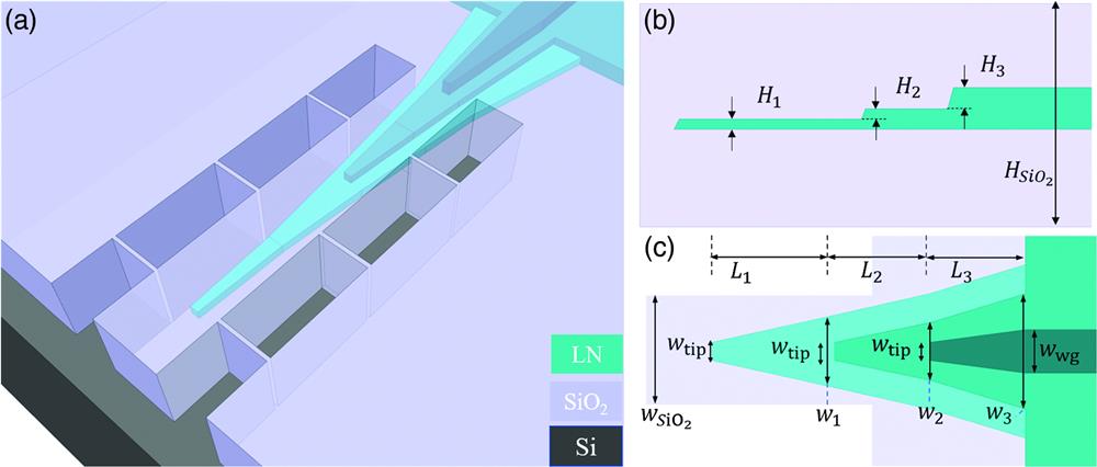
    Fig. 1. (a) Three-dimensional structure schematic diagram of the coupler; (b) cross-sectional view and (c) top view of coupler.
    (a) The simulated overlap between the lensed fiber mode and the SiO2 waveguide mode at 1550 and 775 nm under different waveguide widths. Coupling loss from the SiO2 waveguide to the LN bottom layer at (b) 775 nm and (c) 1550 nm with different bottom dimensions (inset: dimensional parameters of the bottom cone). The simulated curves of coupling lengths (d) L1, (e) L2, and (f) L3 at 1550 and 775 nm. The red stars represent the designed parameter values of the coupler.
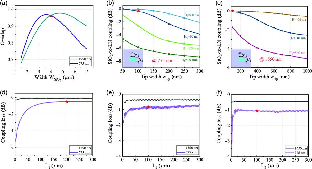
    Fig. 2. (a) The simulated overlap between the lensed fiber mode and the SiO2 waveguide mode at 1550 and 775 nm under different waveguide widths. Coupling loss from the SiO2 waveguide to the LN bottom layer at (b) 775 nm and (c) 1550 nm with different bottom dimensions (inset: dimensional parameters of the bottom cone). The simulated curves of coupling lengths (d) L1, (e) L2, and (f) L3 at 1550 and 775 nm. The red stars represent the designed parameter values of the coupler.
    (a) The simulated distribution of TE00 mode of 1550 and 775 nm at different cross sections I, II, III, IV, and V; simulated mode propagation in the designed coupler at wavelengths (b) 1550 nm and (c) 775 nm.
    Fig. 3. (a) The simulated distribution of TE00 mode of 1550 and 775 nm at different cross sections I, II, III, IV, and V; simulated mode propagation in the designed coupler at wavelengths (b) 1550 nm and (c) 775 nm.
    The simulated coupling efficiency of double-layer structure and tri-layer structure at (a) 1550- and (b) 775-nm band.
    Fig. 4. The simulated coupling efficiency of double-layer structure and tri-layer structure at (a) 1550- and (b) 775-nm band.
    SEM pictures of (a) bottom tip, (b) middle tip, and (c) top tip. (d) SEM picture and (e) larger view of suspended SiO2 waveguide.
    Fig. 5. SEM pictures of (a) bottom tip, (b) middle tip, and (c) top tip. (d) SEM picture and (e) larger view of suspended SiO2 waveguide.
    The coupling losses of the fabricated edge couplers at (a) 1535 to 1565 nm and (b) 765 to 780 nm. Shadowed areas show the standard deviation measured over six devices.
    Fig. 6. The coupling losses of the fabricated edge couplers at (a) 1535 to 1565 nm and (b) 765 to 780 nm. Shadowed areas show the standard deviation measured over six devices.
    (a) Period domain observed by SHG-confocal microscope imaging; red frame is the domain-inverted region. (b) Experimental setup for SHG. FPC, fiber polarization controller; OSA, optical spectrum analyzer. (c) Measured normalized SHG conversion efficiency versus pump wavelengths. (d) Quadratic power dependence of the SH wave on the pump wave.
    Fig. 7. (a) Period domain observed by SHG-confocal microscope imaging; red frame is the domain-inverted region. (b) Experimental setup for SHG. FPC, fiber polarization controller; OSA, optical spectrum analyzer. (c) Measured normalized SHG conversion efficiency versus pump wavelengths. (d) Quadratic power dependence of the SH wave on the pump wave.
    ParameterValue (μm)ParameterValue (μm)ParameterValue (μm)
    MFD for 1550 nm/775 nm3.5/2.5H30.18wwg1.2
    HSiO24wtip0.1L1200
    WSiO24w11.5L2100
    H10.09w21.5L3100
    H20.09w34
    Table 1. Parameters of the designed coupler.
    Ref.Length (mm)ηon-cp (% W1cm2)ηoverall (% W1cm2)Pump/SH coupling loss (dB/facet)
    21630613a10/10
    240.6460057.5a6/7
    26426002.6a10/10
    29537579.65a6.7/12.5
    This work5325610271/3
    Table 2. A comparison with other SHG works based on periodically poled TFLN waveguides.
    Xiaoyue Liu, Shengqian Gao, Chi Zhang, Ying Pan, Rui Ma, Xian Zhang, Lin Liu, Zhenda Xie, Shining Zhu, Siyuan Yu, Xinlun Cai. Ultra-broadband and low-loss edge coupler for highly efficient second harmonic generation in thin-film lithium niobate[J]. Advanced Photonics Nexus, 2022, 1(1): 016001
    Download Citation