• Photonics Research
  • Vol. 6, Issue 6, 525 (2018)
Carlo Edoardo Campanella1、2、*, Martino De Carlo1, Antonello Cuccovillo2, and Vittorio M. N. Passaro1
Author Affiliations
  • 1Photonics Research Group, Dipartimento di Ingegneria Elettrica e dell’Informazione, Politecnico di Bari, Via E. Orabona n. 4, 70125 Bari, Italy
  • 2QOpSyS SRL, Via Matteotti n. 23, 70023 Gioia del Colle, Bari, Italy
  • show less
    DOI: 10.1364/PRJ.6.000525 Cite this Article Set citation alerts
    Carlo Edoardo Campanella, Martino De Carlo, Antonello Cuccovillo, Vittorio M. N. Passaro. Loss-induced control of light propagation direction in passive linear coupled optical cavities[J]. Photonics Research, 2018, 6(6): 525 Copy Citation Text show less
    (a) Physical system consisting of a Fabry–Perot (FP) cavity, made by two fiber Bragg gratings (FBGs) separated by a distance lFP enclosed in an optical fiber loop and excited by EiCW through coupler 1. ACW(0), ACCW(0) are the two counter-propagating modes at the input port (z=0), and ACW(lFP), ACCW(lFP) are the two counter-propagating modes at the output port (z=lFP). (b) Flux diagram of the physical system where two counter-propagating modes (CW and CCW) are excited.
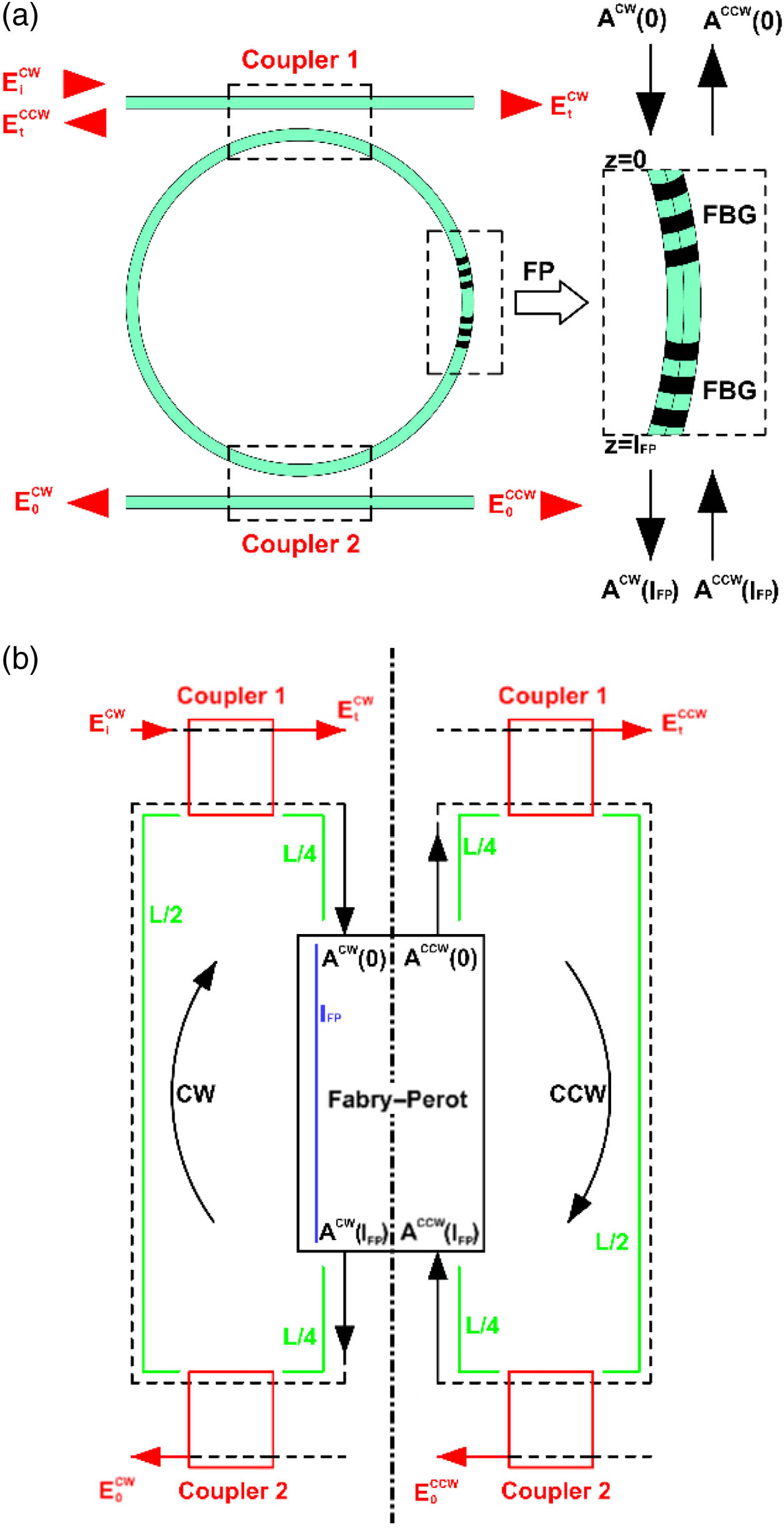
    Fig. 1. (a) Physical system consisting of a Fabry–Perot (FP) cavity, made by two fiber Bragg gratings (FBGs) separated by a distance lFP enclosed in an optical fiber loop and excited by EiCW through coupler 1. ACW(0), ACCW(0) are the two counter-propagating modes at the input port (z=0), and ACW(lFP), ACCW(lFP) are the two counter-propagating modes at the output port (z=lFP). (b) Flux diagram of the physical system where two counter-propagating modes (CW and CCW) are excited.
    Mirror reflection coefficient r and FP attenuation coefficient a, satisfying the condition Asym=0 in the FP ring resonator.
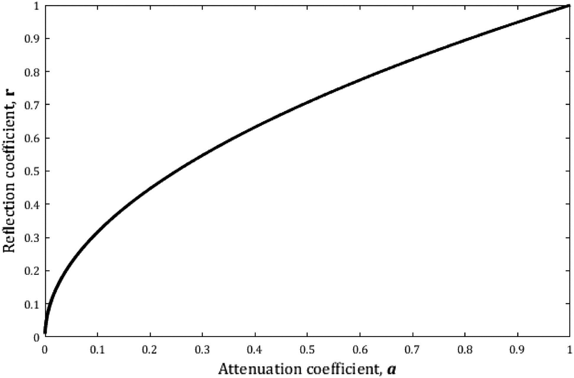
    Fig. 2. Mirror reflection coefficient r and FP attenuation coefficient a, satisfying the condition Asym=0 in the FP ring resonator.
    Contrast ratios with EiCW=1, with r equal to 0.4 (green curves) and 0.9 (yellow curves) and τ equal to 0.5 (dashed curves) and 0.7 (solid curves); contrast ratios with EiCW=1, with τ=0.2214 and r=0.98 (blue curve). Markers I, II are placed in CCW dominance region while markers III, IV are in the CW one. Marker V corresponds to CR=20 dB.
    Fig. 3. Contrast ratios with EiCW=1, with r equal to 0.4 (green curves) and 0.9 (yellow curves) and τ equal to 0.5 (dashed curves) and 0.7 (solid curves); contrast ratios with EiCW=1, with τ=0.2214 and r=0.98 (blue curve). Markers I, II are placed in CCW dominance region while markers III, IV are in the CW one. Marker V corresponds to CR=20  dB.
    (a) Spectral responses of CW exit, |EOCW|2 (dashed curves), and CCW exit, |EOCCW|2 (solid curves), with EiCW=1, with r=0.9, τ=0.7, a=0.65 (red curves) and a=0.95 (blue curves). (b) Spectral responses of CW exit, |EOCW|2 (dashed curves) and CCW exit, |EOCCW|2 (solid curves), with EiCW=1, with r=0.9, τ=0.5, a=0.65 (red curves) and a=0.95 (blue curves).
    Fig. 4. (a) Spectral responses of CW exit, |EOCW|2 (dashed curves), and CCW exit, |EOCCW|2 (solid curves), with EiCW=1, with r=0.9, τ=0.7, a=0.65 (red curves) and a=0.95 (blue curves). (b) Spectral responses of CW exit, |EOCW|2 (dashed curves) and CCW exit, |EOCCW|2 (solid curves), with EiCW=1, with r=0.9, τ=0.5, a=0.65 (red curves) and a=0.95 (blue curves).
    Carlo Edoardo Campanella, Martino De Carlo, Antonello Cuccovillo, Vittorio M. N. Passaro. Loss-induced control of light propagation direction in passive linear coupled optical cavities[J]. Photonics Research, 2018, 6(6): 525
    Download Citation