Abstract
Redirecting the flow of light on the basis of the absorption/gain properties of optical systems is of great interest in many research fields, ranging from optical routing to optical cloaking. In this paper we investigate the control of the direction of the light propagation through loss-induced absorption in passive linear coupled optical systems. The considered optical system consists of a mode-splitting resonant cavity formed by coupling a Fabry–Perot (FP) cavity with a ring resonator. The coalescence of the asymmetric resonances, generated through mode-splitting dynamics, is the spectral result of the parity time symmetry breaking at FP resonance wavelengths. For specific values of the FP overall loss, a predominant backward propagation in the FP ring resonator occurs. In fiber optics technology, this device shows an ability to invert the sense of propagation of the light, quantified through the contrast ratio, in the order of 20 dB. This value can be obtained by externally varying the FP loss coefficient for a fixed set of the other physical parameters of the FP ring resonator. Our results can open a new way toward novel high-performance optical modulation and routing schemes.1. INTRODUCTION
Recently, because of the strong analogy between quantum mechanics and optics, the principles of parity time (PT) symmetry systems and PT symmetry breaking systems have been successfully transferred from the physical context of Hamiltonians describing the features of quantum systems to the scattering matrix describing the spectral properties of optical systems [1]. In this scenario, several investigations about intriguing phenomena consisting of loss-induced transparency [2], nonreciprocal light transmission [3,4], perfect coherent absorption [5,6], enhancement in sensing [7], and non-linearity [8] have been reported in literature. However, the possibility of controlling the propagation direction of light in passive and linear coupled optical cavities has not yet been investigated. An example of passive and linear coupled optical cavities is reported in Fig. 1(a), where a ring resonator including a Fabry–Perot (FP) cavity [constituted of two fiber Bragg gratings (FBGs) placed at a distance ] is sketched. Its flux diagram is reported in Fig. 1(b), where the flow graph represents a coupled ring resonator device obtained by mirroring the device of Fig. 1(a) with respect to the axis passing through the middle of the a FP cavity. Conventionally, a FP ring resonator, as in Fig. 1, is a standing wave resonator, where both forward clockwise (CW) and backward counter-clockwise (CCW) modes are equally excited independently from the sense of the input excitation (supposed to be CW and called in Fig. 1). Thanks to the specific physical conditions, explained in the following sections, it is possible to select a CW or CCW predominant propagation mode (respectively called and in Fig. 1), and the FP ring resonator, which is intrinsically a bidirectional optical system, can become unidirectional. Among these unidirectional conditions, the most interesting one is related to backward propagation (i.e., excitation of exiting mode ), although the input excitation has an opposite sense of propagation. A conventional ring resonator, being a travelling wave (TW) device, allows only the excitation of a forward mode (i.e., with ), while the system under investigation also allows a predominant to be excited with an input. In detail, an FP ring resonator shows a spectral structure characterized by mode splitting [9]. The spectral splitting is due to the presence of two scattering centers (i.e., the two FBGs composing the FP), thus creating a resonant scattering state (i.e., the resonance of the FP). It is intuitive to understand that a mode-splitting resonant system, depending on the splitting dynamics described by means of the scattering matrix, can yield eigenvalues (resonance branches) and asymmetric eigenstates (asymmetric eigenfunctions) that could coalesce at certain points called exceptional points (EPs) [10]. These EPs, being phase singularities of the spectrum associated with the coalescence of both eigenvalues and corresponding eigenstates, lead to many physical effects consisting of level repulsion, crossing, bifurcation, chaos, and phase transitions [11,12], which have been also exploited for generating optical potentials in the context of optomechanics [13]. It has also been demonstrated that it is possible to redirect the flow of light in an active micro device consisting of a whispering-gallery-mode (WGM) laser, where two coupled scattering centers (i.e., two nanoparticles) are used to generate exceptional points [14]. Through the transition from an EP to another one, obtained by manipulating the distance between the two nanoparticles, it is possible to completely reverse the direction of emission of the WGM laser. In the system under investigation in our work, the EP and the PT symmetry breaking occur at a resonant scattering state corresponding to the FP resonance, where eigenvalues and eigenstates coalesce. Moreover, if the Fabry–Perot resonator is long enough, with more Fabry–Perot resonance states present, the system will show a periodical spectral breaking of the PT symmetry. This periodical spectral breaking acts on the overall spectral features of the FP ring resonator, leading to the possibility of redirecting the propagation in a backward direction without the presence of any active or nonlinear medium. In particular, by tuning the structural parameters of the complex system, including the loss of the FP, it is possible to route the flow of the light exiting from the ring resonator in order to excite a predominant backward CCW mode (i.e., ), even in the presence of a forward mode input field (i.e., ).
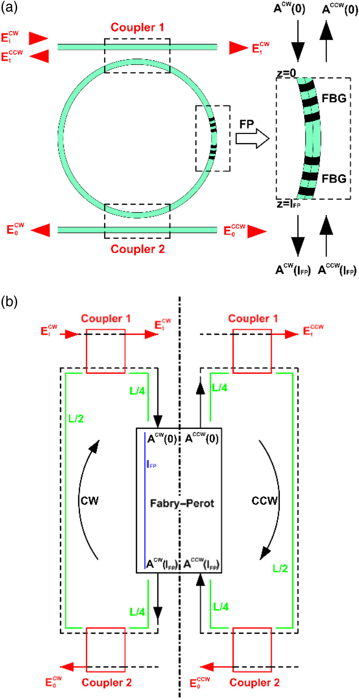
Figure 1.(a) Physical system consisting of a Fabry–Perot (FP) cavity, made by two fiber Bragg gratings (FBGs) separated by a distance enclosed in an optical fiber loop and excited by through coupler 1. , are the two counter-propagating modes at the input port (), and , are the two counter-propagating modes at the output port (). (b) Flux diagram of the physical system where two counter-propagating modes (CW and CCW) are excited.
2. THEORY
In the system shown in Fig. 1(a), a linearly polarized optical field from a laser source () excites the Fabry–Perot ring resonator through the coupler 1. The two evanescent fiber couplers 1 and 2 can be modelled through a transfer matrix whose elements are the forward-transmitted and cross-coupled optical amplitudes and [9]. Each mirror into the Fabry–Perot cavity (i.e., the two FBGs in Fig. 1) is modelled through a transfer matrix, expressed as [2] with and the transmitted and reflected electrical field amplitudes, respectively [9]. To model the Fabry–Perot cavity, we consider , as the amplitudes of the outgoing counter-propagating electric fields, while and are the incoming ones. Thus, the FP cavity can be modeled via a product of transfer matrices [2] where is the propagation constant of the fiber optical mode equal to , with the group index of the propagating optical mode and the wavelength; is the length of the FP cavity, while is the FP attenuation coefficient, and is the loss of the Fabry–Perot cavity per unit length. Now, the following scattering matrix Sc, including the electric field amplitudes transmitted () and reflected () from the FP cavity, can be written as
In particular, where is the electric field amplitude reflected from the Bragg mirror. , , , and in Eq. (2) are linked together using Sc [Eq. (3)] as follows:
By defining the scattering matrix in an open loop, the closure boundary conditions are imposed by considering only a CW excitation (i.e., ) of the ring resonator where is the loss per unit length in the conventional fiber loop.
By substituting Eqs. (7) and (8) in Eq. (6), we obtain that, after some manipulations [15], leads to where is given by
The eigenvalues of the system correspond to those for which the determinant of the matrix is equal to zero,
The solutions of this equation are two complex eigenvalues where is an integer corresponding to the resonance order of the ring resonator. and are complex eigenvalues, depending also on the argument of and , respectively.
Now, by considering the stand-alone FP cavity, it resonates if where is an integer corresponding to the resonance order of the FP cavity, and is the attenuation coefficient inside the FP cavity.
Now, by considering the two resonance orders and , it is possible to verify that, by setting (i.e., by imposing a specific integer as resonance order of the ring resonator), the real and imaginary parts of and always coalesce at (for each when ). This means that many EPs, spectrally placed at the FP resonances, are generated, and that the PT symmetry is broken at those points.
The outgoing optical fields are a forward mode, , and a backward mode, , if the exciting field is CW. They are evaluated by solving the system of Eq. (10) [6,9] where the symmetric and anti-symmetric solutions are respectively given by
With reference to Eqs. (15) and (16), the condition for which the CW mode is equal to the CCW mode is easily obtained for . If , CW and CCW mode powers result to be unbalanced.
At the FP resonance, the condition is verified when
This leads to the following relation between and :
Thus, for each , the condition is satisfied for specific values of , and it is independent from the coupler features (i.e., and ).
3. RESULTS
In order to appropriately evaluate the ability of the device to invert the sense of the light propagation, we consider the contrast ratio as a figure of merit [4]. Indeed, takes into account the ability of the device of reversing the sense of the flow of light when a CW excitation is imposed in order to route the optical signal in the opposite direction (CCW). In analogy with Ref. [4], is defined as
For the sake of simplicity, we evaluate at the FP resonance condition. In Fig. 2 we report the values of and , which satisfy Eq. (20) at the FP resonance. The condition corresponds to . For each combination of and that does not verify Eq. (20), the CW and CCW powers result to be unbalanced.

Figure 2.Mirror reflection coefficient and FP attenuation coefficient , satisfying the condition in the FP ring resonator.
In Fig. 3 we show at the FP resonance condition as a function of attenuation , with a group index of the single-mode fiber , FP length , fiber loop length , and [9]. In particular, two different cases of FBG amplitude reflection coefficient (, green curves, and , orange curves), and two different values of forward-transmitted optical amplitude (, dashed curves, and , solid curves) have been analyzed. In Fig. 3, positive (negative) values of the correspond to a CCW (CW) dominance. The zero decibel (dB) point results to be a function of the FBG amplitude reflection coefficient , while the slope of the curves, that results to be monotone, changes with coupler transmission coefficient . It can be noticed that for negligible values of loss () the CCW results are almost suppressed, as in a conventional TW ring resonator.
Figure 3.Contrast ratios with , with equal to 0.4 (green curves) and 0.9 (yellow curves) and equal to 0.5 (dashed curves) and 0.7 (solid curves); contrast ratios with , with and (blue curve). Markers I, II are placed in CCW dominance region while markers III, IV are in the CW one. Marker V corresponds to .
To experimentally record the spectral responses of the FP ring resonator, an integrated cavity output technique can be used [6], and the can be adjusted through a fine tuning of the FP loss (by adjusting a tunable absorber inserted along the optical path ) while the slope can be controlled through the features of the couplers (by adjusting the coupling coefficients of two tunable couplers).
In Fig. 4, we report the spectral responses of the CW and CCW outputs, with a CW excitation (i.e., , dashed curves, and , solid curves, respectively, with ), when the reflection coefficient of the FBG mirror [i.e., in Eq. (1)] is equal to , which represents a value for medium-reflectivity FBGs. In particular, in Fig. 4(a) the spectral responses of the system are shown for and (marker I in Fig. 2) and (marker II in Fig. 2), whereas in Fig. 4(b) the CW and CCW responses are evaluated for and (marker III in Fig. 2) and (marker IV in Fig. 2). Intuitively, both Figs. 4(a) and 4(b) show the ability of the device to invert the sense of light propagation.
Figure 4.(a) Spectral responses of CW exit, (dashed curves), and CCW exit, (solid curves), with , with , , (red curves) and (blue curves). (b) Spectral responses of CW exit, (dashed curves) and CCW exit, (solid curves), with , with , , (red curves) and (blue curves).
In particular, for and (marker I) a of 2.672 dB has been achieved, while for and (marker II) is equal to .
For and (marker III) is 4.247 dB, while for and (marker IV) is .
For different combinations of and (e.g., and ) when , it is possible to achieve contrast ratios greater than 20 dB (see blue curve in Fig. 3 with marker V focusing on the 20 dB value). With the same combinations of and , the results to be less than when .
Although the results reported in Figs. 3 and 4 demonstrate that when the attenuation is varied, the output power is also modulated (similarly to Refs. [16] and [17]), the proposed system exhibits the same physical effect by coupling linear and passive cavities and achieving the condition of PT symmetry breaking without the need of any active and nonlinear medium.
4. CONCLUSIONS
In conclusion, we have presented the physical principle of optical devices capable of redirecting and routing the flux of the photons. They consist of simple architectures made by passive and linear Fabry–Perot ring resonators, where the flow of light can be routed by varying the FP loss. More particularly, for a specific FP mirror coefficient, it is possible to excite a predominant forward (CW) or backward (CCW) propagation mode by properly tuning the FP loss coefficient. In fiber optics technology, this device allows the control of the direction of light propagation and the possibility to obtain a backward propagation with a contrast ratio of 20 dB. High-performance loss-induced optical modulation and routing techniques can be easily conceived by exploiting the physics of these systems. More generally, our investigations extend the concept of the control of light propagation due to the exceptional points and the PT symmetric systems, from active coupled cavities to passive ones, consisting of ring resonators coupled to an FP cavity. This work significantly contributes to the field because it demonstrates that in these optical systems the predominant backward propagation does not require a nonlinear regime but only the achievement of the condition of PT symmetry breaking and precise design of structural parameters. Although we report our investigations in fiber optics technology and for a specific architecture of coupled cavities (i.e., FP ring resonators), our results can be extended to integrated optics technology and other coupled cavities configurations (e.g., 1D photonic crystal ring resonators and other architectural solutions).
Acknowledgment
Acknowledgment. We thank our colleague Lorenzo Vaiani for graph plots and technical illustration.
References
[1] C. E. Ruter, K. G. Makris, R. El-Ganainy, D. N. Christodoulides, M. Segev, D. Kip. Observation of parity-time symmetry in optics. Nat. Phys., 6, 192-195(2010).
[2] A. Guo, G. J. Salamo, D. Duchesne, R. Morandotti, M. Volatier-Ravat, V. Aimez, G. A. Siviloglou, D. N. Christodoulides. Observation of PT-symmetry breaking in complex optical potentials. Phys. Rev. Lett., 103, 093902(2009).
[3] L. Feng, Y.-L. Xu, W. S. Fegadolli, M.-H. Lu, J. E. B. Oliveira, V. R. Almeida, Y.-F. Chen, A. Scherer. Experimental demonstration of a unidirectional reflectionless parity-time metamaterial at optical frequencies. Nat. Mater., 12, 108-113(2013).
[4] Y. Huang, G. Veronis, C. Min. Unidirectional reflectionless propagation in plasmonic waveguide-cavity systems at exceptional points. Opt. Express, 23, 29882-29895(2015).
[5] S. Longhi. PT-symmetric laser absorber. Phys. Rev. A, 82, 031801(2010).
[6] P. Malara, C. E. Campanella, A. Giorgini, S. Avino, P. De Natale, G. Gagliardi. Super-resonant intra-cavity coherent absorption. Sci. Rep., 6, 28947(2016).
[7] W. Chen, Ş. K. Özdemir, G. Zhao, J. Wiersig, L. Yang. Exceptional points enhance sensing in an optical microcavity. Nature, 548, 192-196(2017).
[8] B. Peng, Ş. K. Özdemir, F. Lei, F. Monifi, M. Gianfreda, G. L. Long, S. Fan, F. Nori, C. M. Bender, L. Yang. Parity-time-symmetric whispering-gallery microcavities. Nat. Phys., 10, 394-398(2014).
[9] C. E. Campanella, L. Mastronardi, F. De Leonardis, P. Malara, G. Gagliardi, V. M. N. Passaro. Investigation of fiber Bragg grating based mode-splitting resonant sensor. Opt. Express, 22, 25371-25384(2014).
[10] H. Ramezani, H.-K. Li, Y. Wang, X. Zhang. Unidirectional spectral singularities. Phys. Rev. Lett., 113, 263905(2014).
[11] W. D. Heiss. Exceptional points of non-Hermitian operators. J. Phys. A, 37, 2455-2464(2004).
[12] W. D. Heiss. Repulsion of resonance states and exceptional points. Phys. Rev. E, 61, 929-932(2000).
[13] P. T. Rakich, M. A. Popovic, M. Soljai, E. P. Ippen. Trapping, corralling and spectral bonding of optical resonances through optically induced potentials. Nat. Photonics, 1, 658-665(2007).
[14] B. Peng, S. K. Odzemir, M. Liertzer, W. Chen, J. Kramer, H. Yrlmaz, J. Wiersig, S. Rotter, L. Yang. Chiral modes and directional lasing at exceptional points. Proc. Natl. Acad. Sci. USA, 113, 6845-6850(2016).
[15] C. E. Campanella, P. Malara, C. M. Campanella, F. Giove, M. Dunai, G. Gagliardi, V. M. N. Passaro. Mode splitting cloning in birefringent fiber Bragg grating ring resonators. Opt. Lett., 41, 2672-2675(2016).
[16] M. Liertzer, L. Ge, A. Cerjan, A. Stone, H. E. Türeci, S. Rotter. Pump-induced exceptional points in lasers. Phys. Rev. Lett., 108, 173901(2012).
[17] B. Peng, S. K. Odzemir, S. Rotter, H. Yilmaz, M. Liertzer, F. Monifi, C. Bender, F. Nori, L. Yang. Loss-induced suppression and revival of lasing. Science, 346, 328-332(2014).


