
Liang Guo, Yanan Guo, Junxi Wang, Tongbo Wei. Ultraviolet communication technique and its application[J]. Journal of Semiconductors, 2021, 42(8): 081801
- Journal of Semiconductors
- Vol. 42, Issue 8, 081801 (2021)
![(Color online) An example of UVC system and network[4].](/richHtml/jos/2021/42/8/081801/img_1.jpg)
Fig. 1. (Color online) An example of UVC system and network[4 ].
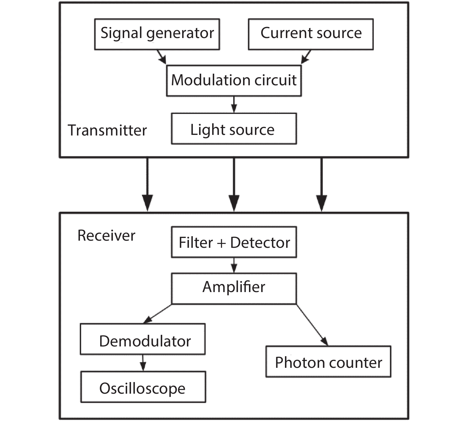
Fig. 2. The typical configuration of UVC.
Fig. 3. (Color online) The spectrum of solar radiation on earth[37 ].
Fig. 4. Typical channel models of UVC: (a) LOS model, (b) NLOS model.
Fig. 5. (Color online) The schematic of the experimental setup for UV laser-based NLOS UWOC[33 ].
Fig. 6. (Color online) (a) Optical spectra of the LED under a bias voltage of 7 V[64 ]. (b) The small-signal frequency response of the system. The dashed line indicates the –3 dB bandwidth, which is approximately 29 MHz at distance = 0[64 ]. (c) The modulation bandwidth of the system at a distance of 5 m with different injection currents[60 ]. (d) The experimental setup and the flow diagram of the signal generation and offline processing[60 ].
Fig. 7. (Color online) (a) A 4 × 4 matrix device structure with a single device size of 60 μ m, with the corresponding changes in device response frequency and current[75 ]. (b) Simplified cross-sectional schematic of a single DUV μ LED presented in this work. Dimensions are not to scale[34 ]. (c) Plan view optical image of the fabricated DUV μ LED array presented in this work[34 ]. (d) The 3 dB electrical modulation bandwidth of the DUV μ LED as a function of current density[34 ].
Fig. 8. (a) Normalized PL decay kinetics for AlGaN MQW structures with different well widths: (1) 5 nm, (2) 4.1 nm, and (3) 2.5 nm. Measurements were performed under excitation energy density of 25 mJ/cm2[90 ]. (b) Well-width dependence of carrier lifetimes for AlGaN MQW structures at excitation energy density of 70 μ J/cm2[90 ]. (c) Lifetime for different temperatures derived from the TD-TRPL results[91 ].
Fig. 9. (Color online) (a) The experimental setup of the receiver side[66 ]. (b) The experimental setup[19 ]. (c) Experimental setup for solar-blind NLOS UV communication with diversity reception[30 ].
Fig. 10. Application of UVC in aircraft squad.
|
Table 1. Comparison of DUV light sources in UVC system.
|
Table 2. Recent progress in UVC using LED as the light source.
|
Table 3. Comparison of DUV detectors in UVC system.

Set citation alerts for the article
Please enter your email address
© Copyright 2018-2021 | Chinese Laser Press. All Rights Reserved 沪ICP备15018463号-20