
Liang Guo, Yanan Guo, Junxi Wang, Tongbo Wei. Ultraviolet communication technique and its application[J]. Journal of Semiconductors, 2021, 42(8): 081801
- Journal of Semiconductors
- Vol. 42, Issue 8, 081801 (2021)
Abstract
1. Introduction
Optical wireless communication (OWC) has been a research hot spot for decades[
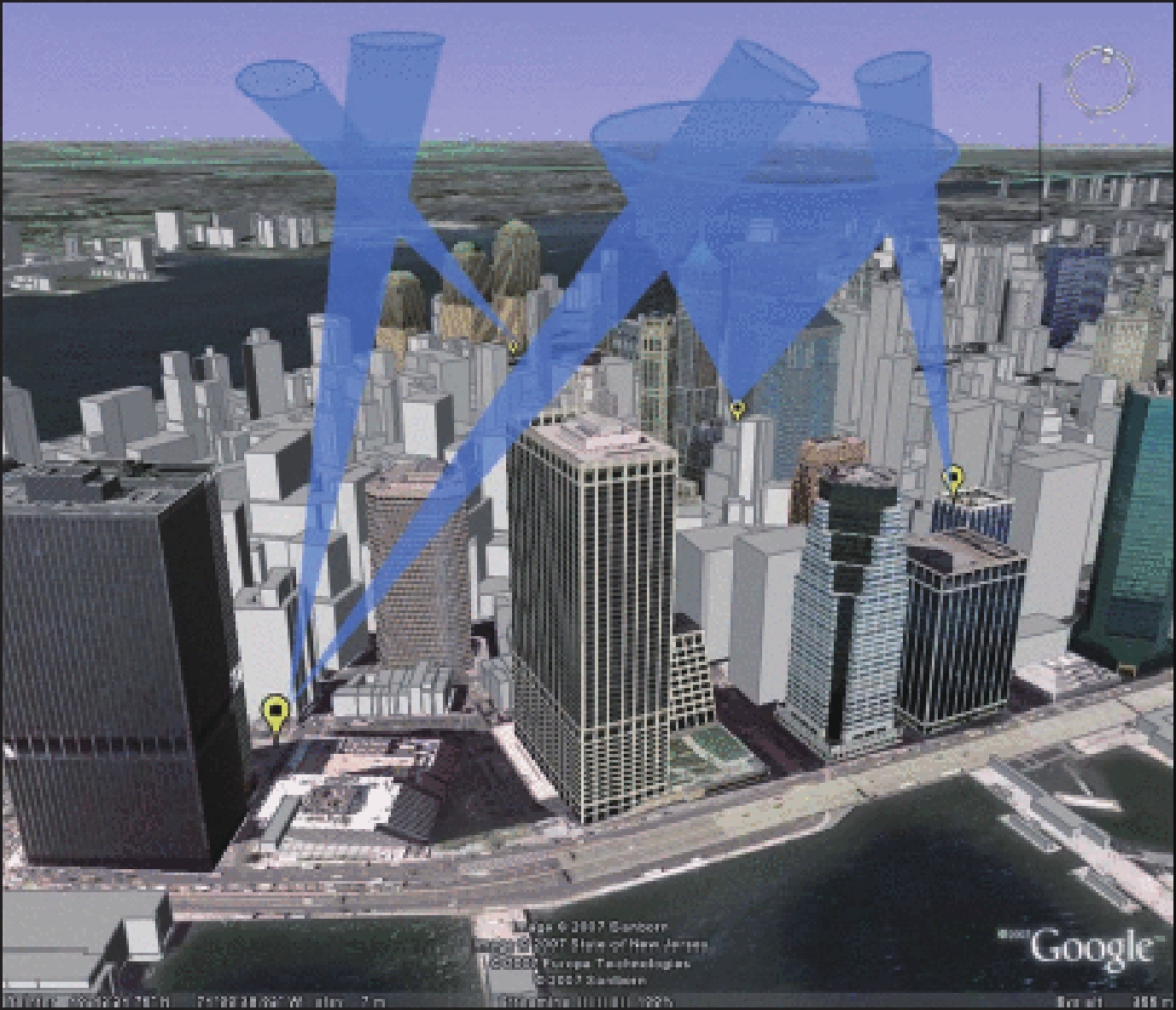
As a novel communication technique, UVC utilizes UV radiation to transmit signals which can be scattered and reflected by the particles and aerosols floating in the air. Its transmission range can be extended up to several kilometers regardless of the topographic features on the ground. Compared to traditional wireless communication, UVC has several unique features that render it a promising communication technique for future applications. Traditional wireless communication demands an obstacle-free communication channel between transceivers, while UVC can easily bypass these obstacles through scattering and reflection. The UV radiation employed in communication is also called solar-blind radiation which is located between 200–280 nm in the DUV spectrum. Most solar-blind radiation is absorbed by ozone and oxygen when passing through the atmosphere, which leaves a low background-noise communication channel near the ground[
![]()
Figure 1.(Color online) An example of UVC system and network[
In this article, we summarize and describe the history and working principle of UVC. A comprehensive comparison of its light sources and detectors is provided to the best of our knowledge. Then we discuss the research progress of UVC from a device perspective. For light sources, our review is based on three of the most used UV light sources including a gas discharge lamp, laser and LED. For detectors, other than the commonly-used detectors including photomultiplier tubes (PMTs) and semiconductor photodetectors (PDs), we also discuss some potential solar-blind detectors for UVC. Finally, we present the application and outlook of UVC. Hopefully, this review will offer valuable insights into the future development of UVC.
2. Development history of UVC
UVC was first put forward in the 1930s. Hulburt from the Naval Research Laboratory summarized their work from 1926 to 1933 in a report called “Signaling and Detection with Ultra-Violet and Infra-Red Radiation”[
In 1994, Charles et al. first proposed solid-state lasers as the light sources for UVC. A compact quadrupled Nd:YAG laser was used to prove the feasibility[
The US Defense Advanced Research Projects Agency (DARPA) launched two programs involving developing novel light sources and detectors for future military use in 2002 and 2007: the Semiconductor UV Optical Source (SUVOS) program and the Deep Ultraviolet Avalanche Photodiode (DUVAP) program. These two programs sponsored numerous pieces of research on DUV light sources and solar-blind detectors, which further boosted the development of UVC based on DUV light sources and solar-blind detectors. In 2006, a 24-unit array LED with wavelength of 274 nm and output power of 40 mW was demonstrated by Shaw et al.[
UVC research in China was first started by the Beijing Institute of Technology in the 1990s[
In 2009, researchers from Ben Gurion University in Israel developed an underwater UVC system based on 250 nm LED[
The National University of Defense Technology began the study on UVC in 2000. Jia et al. conducted several experiments on the scatter propagation model of the UV light based on the Monte Carlo method[
UVC research in Beijing University of Posts and Telecommunications started in 2010. Zuo et al. studied path loss in a novel single-scatter model based on Monte Carlo simulation[
Studies at King Abdullah University of Science & Technology mainly focused on underwater UVC. Research based on laser and LED have been published successively [
3. Working principle of UVC
3.1. Configuration of UVC
A typical configuration of UVC is shown in Fig. 2. The transmitter side consists of the signal generator, current sources, modulation circuits and light sources such as DUV LEDs, DUV lasers, or mercury lamps. The electrical signals from the signal generator are coded by a modulation circuit and converted into high-frequency currents. Then high-frequency currents are amplified by current sources and supplied to light sources to generate light signals.
![]()
Figure 2.The typical configuration of UVC.
The receiver side consists of a solar-blind filter, UV detectors (usually PMT, p–i–n photodiode (PIN), or avalanche photodiode (APD)), signal amplifier, demodulator and so on. The light signal detected by the UV detector will be converted back into the electrical signal. In order to increase the SNR, a signal amplifier is required to increase signal power. After demodulation and reconstruction, the signal will be restored.
3.2. Atmosphere propagation
When passing through the atmosphere, solar radiation is strongly scattered, absorbed, or reflected by the water vapor, carbon dioxide, fine particles, oxygen, ozone and other gas molecules in the air, causing discontinuities in the solar spectrum. Of all the molecules and particles, ozone which accounts for only 0.01%–0.1% of the atmosphere has a strong absorption band in the UV spectrum[
![]()
Figure 3.(Color online) The spectrum of solar radiation on earth[
Atmospheric scattering is the basis of NLOS UVC. When the light propagates in the atmosphere, its electromagnetic field will oscillate with the charges of particles floating in the air, which will generate one or more dipoles that radiate secondary spherical waves with the same frequency and phase as the original ones[
Assuming that the intensity of monochromatic light radiation is I, the absorption caused by atmospheric scattering and absorption obeys the Lambert–Beer law[
I0 is the luminous flux before absorption, I is the luminous flux after absorption, l is the transmission distance and μ(λ) is the light’s atmospheric attenuation coefficient of the wavelength of λ per distance unit. Atmospheric attenuation coefficient can be derived from the following expression:
3.3. Channel model
UVC has two channel models: LOS model and NLOS model. The pointing angles of the transmitter and receiver in the LOS model require rigorous regulations to ensure that they are on the same horizontal line. The LOS model is suitable for point-to-point communication at a relatively short distance without obstacles between the transmitter side and receiver side. Path loss in the LOS model mainly derives from atmosphere absorption and scattering.
The LOS model is shown in Fig. 4(a). TX represents the transmitter side, RX represents the receiver side,
![]()
Figure 4.Typical channel models of UVC: (a) LOS model, (b) NLOS model.
The received power is:
Here,
According to the geometric relationship in Fig. 4(a),
The received power can be further simplified into:
According to Eq. (10), the received power is affected by the transmission distance r, the divergence angle of the light source
In the NLOS model, the beam divergence angle of the transmitter and the FOV of the receiver are not directly pointing at each other. There are obstacles between the transmitter and receiver. In this case, the light signal can be received by detectors after multiple atmospheric scattering. A diagram of the NLOS model is shown in Fig. 4(b).
The final received power of the NLOS model can be simplified as
r is the distance between transmitter and receiver,
3.4. Modulation
In UVC, light signals can be easily interfered by the background light noise during the propagation. Signals need to be superimposed on light waves which act as carrier waves to improve the stability and reliability of UVC. The intensity, frequency, phase, polarization of the carrier waves are modulated by the signals. The light signals that reach the photodetector will be demodulated to restore the original signal after opto-electrical (O-E) conversion.
Some of the most prevailing modulation schemes include OOK, pulse position modulation (PPM), fixed-length digital pulse interval modulation (FDPIM) and digital pulse interval modulation (DPIM). Different modulation schemes vary in terms of power utilization rate, frequency band utilization rate, channel capacity and inter-symbol interference. As the most used intensity modulation / direct detection (IM/DD) modulation scheme, OOK has the highest frequency band utilization rate and lowest inter-symbol interference, but its power utilization rate is the lowest among these four modulation schemes. Besides, OOK is easy to implement with no complex modulator circuits required. PPM has the highest frequency band utilization rate, making it suitable for long-range and high background noise UVC systems.
4. Light sources of UVC
UV light source is one of the most critical components of the UVC system. Its optical power essentially determines transmission distance of UVC, while its bandwidth has a major impact on the data rate. As for the wavelength, shorter-wavelength signal will be less affected by the background noise, enabling a higher SNR for UVC. Gas discharge lamps, lasers and LEDs are the three most used light sources in the UVC system. Gas discharge lamps have great advantages in cost and output power. However, lasers excel in their high coherence, high monochromaticity and low divergence. They both share the same deficiency of heavy volume, large power consumption and low modulation rate. AlGaN-based LED has gained more and more attention in UVC due to its higher modulation rate and smaller chip size. By packaging multiple LED chips into one source array, its output power can reach up to Watt range. When reducing its size to the micrometer range, its bandwidth can reach up to GHz level[
4.1. DUV gas discharge lamp
As the first-used light source, the gas discharge lamp has a long history in UVC. Some of the most used UV gas discharge lamps include high and low-pressure mercury lamps, UV halide lamps and mercury xenon lamps. The conversion efficiency of the low-pressure mercury lamp can reach up to 30%–40%. In 1976, hydrogen-xenon arc lamps with high pulse repetition rates were used in the investigation of ultraviolet voice communication by Fishburne et al.[
4.2. DUV laser
Although gas discharge lamps have great advantages in output power, it still suffers from fragility and short lifetime. People begin to turn to other solar-blind sources like DUV laser. In 2010, an experimental test-bed using a narrow-pulsed ultraviolet (UV) laser was set up to characterize pulse broadening effects in short-range NLOS UVC channels by Chen et al.[
![]()
Figure 5.(Color online) The schematic of the experimental setup for UV laser-based NLOS UWOC[
4.3. DUV LED
4.3.1. Introduction to DUV LED
As a pollution-free, low cost and high-efficiency optoelectronic device, AlGaN-based LEDs are replacing conventional mercury lamps as DUV light sources in many applications like sterilization, curing and medical diagnostics[
As the most ideal light source for UVC, the emission wavelength of AlGaN-based LEDs can be tuned from 210 to 360 nm which covers the entire solar-blind spectrum. Besides, LEDs exceed other light sources in bandwidth and response speed as well, facilitating its application in optical communication[
Sun et al. demonstrated a UVB-LED-based communication channel with a high data rate of 71 Mb/s. The proposed LED had an output power of 190 μW at 7 V bias voltage, wavelength of 294 nm and a –3 dB bandwidth of 29 MHz, as plotted in Figs. 6(a) and 6(b)[
![]()
Figure 6.(Color online) (a) Optical spectra of the LED under a bias voltage of 7 V[
4.3.2. Approaches to improve DUV LED bandwidth
Generally, the bandwidth of LEDs is affected by two factors: RC time constant[
![]()
Figure 7.(Color online) (a) A 4 × 4 matrix device structure with a single device size of 60
As a recent research hotspot, micro-LED shows great potential in high-speed optical communication[
Carrier lifetime can also be effectively reduced by optimizing the MQW structure. LEDs with a thinner QW show a higher carrier density in the individual QW and a smaller spatial separation of the electron and hole wave functions by quantum-confined stark effect (QCSE)[
![]()
Figure 8.(a) Normalized PL decay kinetics for AlGaN MQW structures with different well widths: (1) 5 nm, (2) 4.1 nm, and (3) 2.5 nm. Measurements were performed under excitation energy density of 25 mJ/cm2[
Quantum barrier height in MQW is modulated by its aluminum composition, which will further impact the radiative recombination rate and output power of DUV LEDs[
In 2017, Tian et al. investigated the impact of Si-doped AlGaN quantum barriers on the hole distribution in the MQWs, the radiative recombination rate and the optical powers of AlGaN DUV LED[
Surface plasmon (SPs) can change the optical environment of the emitter due to its near-field enhancement properties. When the LED’s MQW is coupled with SPs, a new energy conversion channel is added to the electron-hole pair. Thus, the energy of the electron-hole pair can be directly transferred to the SP, increasing the spontaneous radiative rate and reducing the carrier lifetime[
The electron blocking layer (EBL) between the p-type layer and active region in AlGaN-based LED can block the electrons overflowing from the active region and increase carrier residence time in MQW. However, EBL will also prevent the hole in the p-type layer from entering the active region. Numerical and experimental results indicate that LED with low barrier height EBL shows higher radiative recombination rate and hole injection efficiency, thereby leading to higher modulation bandwidth[
5. Detectors of UVC
As the most crucial components in the receiver side of UVC, detectors have a major impact on the BER and SNR of UVC. PMT is one of the most used PDs in scientific research due to their superior sensitivity and responsivity, especially in the detection of ultrashort pulse light and ultra-weak photons. Compared to the PIN and APD, PMT has a larger detection area, lower dark current and higher multiplication gains. But it is also fragile, expensive, and requires expensive solar-blind filters that fail to meet the trends of miniaturization for UVC. Besides, its bandwidth is merely 50 MHz, much lower than the commonly used Si-based detectors and SiC-base detectors. Semiconductor detectors like PINs and APDs still suffer from relatively high dark current and noise, which is about 5–6 orders of magnitude higher than PMT. APDs work under a much higher reverse bias than PDs, which increases the current gain to the order of 1000[
5.1. PMTs
PMT has a long history in UVC, which is also the most used detectors since UVC is first put forward. Xing et al. studied the 2 × 2 MIMO scheme for UVC using two independent PMTs as the detectors, which have a 3 dB bandwidth of 5 MHz[
![]()
Figure 9.(Color online) (a) The experimental setup of the receiver side[
5.2. Semiconductor PDs
Recently, the commercially available Si and SiC-based PINs and APDs have been replacing PMT in more and more scenarios. SiC-based PD shows excellent UV responsivity characteristics and a very low dark current between 200 and 400 nm. The responsivity at 270 nm is between 150 and 175 mA/W with a quantum efficiency of between 70% and 85%[
AlGaN-based APDs are intrinsically solar-blind with no additional filters required and are an ideal alternative to current bulky and fragile PMTs. In 2014, Shao et al. reported an AlGaN-based APD with a record-high gain of 1.2 × 10⁴ and a peak responsivity of 0.15 A/W around 280 nm[
5.3. Potential detectors for UVC
Recently, solar-blind detectors with novel material and device structure have been proposed extensively, among which Ga2O3, ZnO-Ga2O3 and MgZnO based detectors have shown great potential in replacing the current solar-blind detectors for UVC. With its wide bandgap of 4.9 eV, Ga2O3-based PDs are perfectly fit for solar-blind detection in UVC[
The lattice mismatch between ZnO and Ga2O3 is relatively small, making it easier to grow Ga2O3 on ZnO. And the large conduction band offsets between Ga2O3 and ZnO prompt large avalanche multiplication which leads to larger responsivity. Zhao et al. proposed a single core-shell microwire APDs based on ZnO–Ga2O3 heterostructure[
MgZnO is another promising candidate for solar-blind PDs. Theoretically, the bandgap of MgZnO can be tuned from 3.4 to 7.8 eV by changing the Mg content. But the fabrication technique for MgZnO is still in its infancy due to the large mismatch between the MgZnO epilayer and its common substrates. Du et al. first proposed MgZnO-based solar-blind PDs in 2009[
6. Future application of UVC
UVC has a lot of potential applications in underwater communication, vehicular communication and machine-to-machine communication. The frequency band used in UVC is much higher than that of radio frequency (RF) communication, so traditional electromagnetic interference (EMI) technology and signal interception technology cannot be applied to UVC, guarenteeing confidential and interference-free communication environment for UVC. We present some scenarios where UVC can be a viable alternative to conventional communication.
6.1. Battlefield applications
On the battlefield, radio sometimes needs to be turned off to conceal operation. Under this circumstance, gestures or code words will usually be used for short-range communication. By using UVC as the alternative, unicast, multicast and broadcast communications will be possible. Short-range communication in conventional tactical operations usually requires cable, but the cable set-up requires extra time severely restraining the speed and maneuverability of operation. While UVC systems can be quickly set up with no cable required.
6.2. Aircraft guidance system
UVC can also be used in take-off guidance systems among control towers, aircraft carriers and aircraft[
6.3. Aircraft squad communication
UVC systems can be used for confidential communications among aircraft squad as shown in Fig. 10. In this case, each aircraft is equipped with a transceiver system. The transmitter radiates light signals in a horizontal direction and the receiver is mounted facing the sky to collect UV signals scattered into its FOV to build electromagnetically silent and secure internal communications.
![]()
Figure 10.Application of UVC in aircraft squad.
7. Conclusion and outlook of UVC
In this article, we summarize and describe the history and working principle of UVC. A comprehensive comparison of its light sources and detectors is provided to the best of our knowledge. Then we discuss the research progress of UVC from a device perspective. For light sources, our review is based on three of the most used UV light sources including gas discharge lamp, laser and LED. For detectors, other than the commonly used detectors including PMTs and semiconductor PDs, we also discuss some potential solar-blind detectors for UVC. Finally, we present the application and outlook of UVC. Hopefully, this review will offer valuable insights into the future development of UVC.
As a novel optical communication, UVC shows great potential in replacing conventional communication. Rich theory on the networking, channel model, modulation scheme and signal processing have been put forward and verified experimentally[
Acknowledgements
This work was financially supported by the National Key R&D Program of China (No. 2019YFA0708203), the National Natural Science Foundation of China (No. 61974139), and the Beijing Natural Science Foundation (No. 4182063).
References
[1] M A Khalighi, M Uysal. Survey on free space optical communication: A communication theory perspective. IEEE Commun Surv Tutor, 16, 2231(2014).
[2] S Rajbhandari, J J McKendry, J Herrnsdorf et al. A review of gallium nitride LEDs for multi-gigabit-per-second visible light data communications. Semicond Sci Technol, 32, 023001(2017).
[3] G A Shaw, M L Nischan, M A Iyengar et al. NLOS UV communication for distributed sensor systems. International Symposium on Optical Science and Technology, 83(2000).
[4] Z Xu, B M Sadler. Ultraviolet communications: potential and state-of-the-art. IEEE Commun Mag, 46, 67(2008).
[5]
[6]
[7]
[8] B Charles, B Hughes, A Erickson et al. Ultraviolet laser-based communication system for short-range tactical applications. OE/LASE '94, 79(1994).
[9] G A Shaw, A M Siegel, J Model et al. Field testing and evaluation of a solar-blind UV communication link for unattended ground sensors. Defense and Security, 250(2004).
[10] G A Shaw, A M Siegel, J Model. Extending the range and performance of non-line-of-sight ultraviolet communication links. Defense and Security Symposium, 62310C(2006).
[11] Z Xu, M K Tsatsanis. Blind adaptive algorithms for minimum variance CDMA receivers. IEEE Trans Commun, 49, 180(2001).
[12] Z Xu, G Chen, F Abou-Galala et al. Experimental performance evaluation of non-line-of-sight ultraviolet communication systems. Optical Engineering + Applications, 67090Y(2007).
[13] Z Xu, H Ding, B M Sadler et al. Analytical performance study of solar blind non-line-of-sight ultraviolet short-range communication links. Opt Lett, 33, 1860(2008).
[14] L D Liu, G Q Ni, S D Zhong et al. Application and detection of ultraviolet and their new development. Opt Technol, 2, 87(1998).
[15] G Q Ni. Study on ultraviolet communication through disengaged atmodphere. Opt Tech, 26, 297(2000).
[16] Y Tang, G Ni, L Zhang et al. Study of single scatter model in NLOS UV communication. Opt Tech, 33, 759(2007).
[17] Y Tang, Z L Wu, G Q Ni et al. NLOS single scattering model in digital UV communication. Asia-Pacific Opt Communi, 713615(2008).
[18] D Kedar, S Arnon. Subsea ultraviolet solar-blind broadband free-space optics communication. Opt Eng, 48, 046001(2009).
[19] N Raptis, E Pikasis, D Syvridis. Power losses in diffuse ultraviolet optical communications channels. Opt Lett, 41, 4421(2016).
[20] H Yin, S Chang, X Wang et al. Analytical model of non-line-of-sight single-scatter propagation. J Opt Soc Am A, 27, 1505(2010).
[21] H Yin, S Chang, H Jia et al. Non-line-of-sight multiscatter propagation model. J Opt Soc Am A, 26, 2466(2009).
[22] H Zhang, H Yin, H Jia et al. Study of effects of obstacle on non-line-of-sight ultraviolet communication links. Opt Express, 19, 21216(2011).
[23]
[24] H Yin, J Yang, S Chang et al. Analysis of several factors influencing range of non-line-of-sight UV transmission. Asia-Pacific Optical Communications, 67833E(2007).
[25] H Jia, H X Huang, H Zhang. Influence factors on data speed of wireless ultraviolet communication. Optics & Optoelectronic Technology, 1, 20(2010).
[26] Y Zuo, H Xiao, J Wu et al. A single-scatter path loss model for non-line-of-sight ultraviolet channels. Opt Express, 20, 10359(2012).
[27] Y Zuo, Jian Wu, H F Xiao et al. Non-line-of-sight ultraviolet communication performance in atmospheric turbulence. China Commun, 10, 52(2013).
[28] H Xiao, Y Zuo, J Wu et al. Non-line-of-sight ultraviolet single-scatter propagation model in random turbulent medium. Opt Lett, 38, 3366(2013).
[29] L Guo, D Meng, K Liu et al. Experimental research on the MRC diversity reception algorithm for UV communication. Appl Opt, 54, 5050(2015).
[30] X Meng, M Zhang, D Han et al. Experimental study on 1× 4 real-time SIMO diversity reception scheme for a ultraviolet communication system. European Conference on Networks and Optical Communications (NOC), 1(2015).
[31] Z Sun, L Zhang, Y Qin et al. 1 Mbps NLOS solar-blind ultraviolet communication system based on UV-LED array. International Conference on Optical Instruments and Technology 2017, 106170O(2017).
[32] X Sun, W Cai, O Alkhazragi et al. 375-nm ultraviolet-laser based non-line-of-sight underwater optical communication. Opt Express, 26, 12870(2018).
[33] X Sun, M Kong, O Alkhazragi et al. Non-line-of-sight methodology for high-speed wireless optical communication in highly turbid water. Opt Commun, 461, 125264(2020).
[34] X He, E Xie, M S Islim et al. 1 Gbps free-space deep-ultraviolet communications based on III-nitride micro-LEDs emitting at 262 nm. Photonics Res, 7, B41(2019).
[35] K Kojima, Y Yoshida, M Shiraiwa et al. 1.6-Gbps LED-based ultraviolet communication at 280 nm in direct sunlight. 2018 European Conference on Optical Communication (ECOC), 1(2018).
[36] P Laj, J Klausen, M Bilde et al. Measuring atmospheric composition change. Atmos Environ, 43, 5351(2009).
[37] V Walter, M Saska, A Franchi. Fast mutual relative localization of uavs using ultraviolet led markers. 2018 International Conference on Unmanned Aircraft Systems (ICUAS), 1217(2018).
[38]
[39] D F Swinehart. The beer-lambert law. J Chem Educ, 39, 333(1962).
[40] M R Luettgen, J H Shapiro, D M Reilly. Non-line-of-sight single-scatter propagation model. J Opt Soc Am A, 8, 1964(1991).
[41] K A Sholtes, K Lowe, G W Walters et al. Comparison of ultraviolet light-emitting diodes and low-pressure mercury-arc lamps for disinfection of water. Environ Technol, 37, 2183(2016).
[42] T Pousset, P Cussac, G Zissis et al. Electronic ballast for high-pressure mercury lamps. 1996 IEEE Industry Applications Society Annual Meeting, 2109(1996).
[43]
[44]
[45] K X Sun, N Leindecker, S Higuchi et al. UV LED operation lifetime and radiation hardness qualification for space flights. 7th International LISA Symposium, 012028(2008).
[46]
[47]
[48] J J Puschell, R Bayse. High data rate ultraviolet communication systems for the tactical battlefield. Tactical Communications Conference, 253(1990).
[49] G Chen, Z Xu, B M Sadler. Experimental demonstration of ultraviolet pulse broadening in short-range non-line-of-sight communication channels. Opt Express, 18, 10500(2010).
[50] K Wang, C Gong, D Zou et al. Demonstration of a 400 kbps real-time non-line-of-sight laser-based ultraviolet communication system over 500 m. Chin Opt Lett, 15, 040602(2017).
[51] L Liao, R J Drost, Z Li et al. Long-distance non-line-of-sight ultraviolet communication channel analysis: experimentation and modelling. IET Optoelectron, 9, 223(2015).
[52] M Würtele, T Kolbe, M Lipsz et al. Application of GaN-based ultraviolet-C light emitting diodes – UV LEDs – for water disinfection. Water Res, 45, 1481(2011).
[53]
[54] H Hirayama. Research status and prospects of deep ultraviolet devices. J Semicond, 40, 120301(2019).
[55] D Barolet. Light-emitting diodes (LEDs) in dermatology. Semin Cutan Med Surg, 27, 227(2008).
[56] A Khan, K Balakrishnan, T Katona. Ultraviolet light-emitting diodes based on group three nitrides. Nat Photonics, 2, 77(2008).
[57] M Kneissl, T Kolbe, C Chua et al. Advances in group III-nitride-based deep UV light-emitting diode technology. Semicond Sci Technol, 26, 014036(2010).
[58] J Li, G Ji, W Yang et al. Emission mechanism of high Al-content AlGaN multiple quantum wells. Chin J Lumin, 37, 513(2016).
[59] T Komine, M Nakagawa. Fundamental analysis for visible-light communication system using LED lights. IEEE Trans Consum Electron, 50, 100(2004).
[60] O Alkhazragi, F Hu, P Zou et al. 2.4-Gbps ultraviolet-C solar-blind communication based on probabilistically shaped DMT modulation. 2020 Optical Fiber Communication Conference, M3I.5(2020).
[61] O Alkhazragi, F Hu, P Zou et al. Gbit/s ultraviolet-C diffuse-line-of-sight communication based on probabilistically shaped DMT and diversity reception. Opt Express, 28, 9111(2020).
[62] Y Yoshida, K Kojima, M Shiraiwa et al. An outdoor evaluation of 1-Gbps optical wireless communication using AlGaN-based LED in 280-nm band. 2019 Conference on Lasers and Electro-Optics (CLEO), 1(2019).
[63] Y Yang, n X H Chen, u B You et al. Design of solar blind ultraviolet LED real-time video transmission system. Infrared Laser Eng, 47, 1022001(2018).
[64] X Sun, Z Zhang, A Chaaban et al. 71-Mbit/s ultraviolet-B LED communication link based on 8-QAM-OFDM modulation. Opt Express, 25, 23267(2017).
[65] H Qin, Y Zuo, F Li et al. Analytical link bandwidth model based square array reception for non-line-of-sight ultraviolet communication. Opt Express, 25, 22693(2017).
[66] Y Xing, M Zhang, D Han et al. Experimental study of a 2 × 2 MIMO scheme for ultraviolet communications. 2016 15th International Conference on Optical Communications and Networks (ICOCN), 1(2016).
[67] P Song, T Zhao, X Ke et al. Multi-user interference in a non-line-of-sight ultraviolet communication network. IET Commun, 10, 1640(2016).
[68] M Zhang, P Luo, X Guo et al. Spread spectrum-based ultraviolet communication with experiments. Chin Opt Lett, 12, 100602(2014).
[69] Q He, Z Xu, B M Sadler. Performance of short-range non-line-of-sight LED-based ultraviolet communication receivers. Opt Express, 18, 12226(2010).
[70] G Chen, F Abou-Galala, Z Xu et al. Experimental evaluation of LED-based solar blind NLOS communication links. Opt Express, 16, 15059(2008).
[71] J W Shi, C C Chen, J K Sheu et al. Linear cascade GaN-based green light-emitting diodes with invariant high-speed/power performance under high-temperature operation. IEEE Photon Technol Lett, 20, 1896(2008).
[72] J W Shi, J K Sheu, C K Wang et al. Linear cascade arrays of GaN-based green light-emitting diodes for high-speed and high-power performance. IEEE Photon Technol Lett, 19, 1368(2007).
[73] J W Shi, J K Sheu, C H Chen et al. High-speed GaN-based green light-emitting diodes with partially n-doped active layers and current-confined apertures. IEEE Electron Device Lett, 29, 158(2008).
[74] J J McKendry, R P Green, A Kelly et al. High-speed visible light communications using individual pixels in a micro light-emitting diode array. IEEE Photon Technol Lett, 22, 1346(2010).
[75] Y Huang, Z Guo, H Huang et al. Influence of current density and capacitance on the bandwidth of VLC LED. IEEE Photon Technol Lett, 30, 773(2018).
[76] S C Zhu, L X Zhao, C Yang et al. GaN-based flip-chip parallel micro LED array for visible light communication. 2017 International Conference on Optoelectronics and Microelectronics Technology and Application, 102441Y(2016).
[77] J J McKendry, D Massoubre, S Zhang et al. Visible-light communications using a CMOS-controlled micro-light-emitting-diode array. J Light Technol, 30, 61(2011).
[78] R X Ferreira, E Xie, J J McKendry et al. High bandwidth GaN-based micro-LEDs for multi-Gb/s visible light communications. IEEE Photon Technol Lett, 28, 2023(2016).
[79] J Bai, Y Cai, P Feng et al. Ultra-small, ultra-compact and ultra-high efficient InGaN micro light emitting diodes (µLEDs) with narrow spectral linewidth. ACS Nano, 14, 6909(2020).
[80] A Rashidi, M Monavarian, A Aragon et al. Nonpolar
[81] N L Ploch, H Rodriguez, C Stolmacker et al. Effective thermal management in ultraviolet light-emitting diodes with micro-LED arrays. IEEE Trans Electron Devices, 60, 782(2013).
[82] J Zhang, S Wu, S Rai et al. AlGaN multiple-quantum-well-based, deep ultraviolet light-emitting diodes with significantly reduced long-wave emission. Appl Phys Lett, 83, 3456(2003).
[83] S Hwang, M Islam, B Zhang et al. A hybrid micro-pixel based deep ultraviolet light-emitting diode lamp. Appl Phys Express, 4, 012102(2010).
[84] S Wu, S Chhajed, L Yan et al. Matrix addressable micro-pixel 280 nm deep UV light-emitting diodes. Jpn J Appl Phys, 45, L352(2006).
[85] V Adivarahan, S Wu, W Sun et al. High-power deep ultraviolet light-emitting diodes basedon a micro-pixel design. Appl Phys Lett, 85, 1838(2004).
[86] V Adivarahan, A Heidari, B Zhang et al. 280 nm deep ultraviolet light emitting diode lamp with an AlGaN multiple quantum well active region. Appl Phys Express, 2, 102101(2009).
[87] W Sun, V Adivarahan, M Shatalov et al. Continuous wave milliwatt power AlGaN light emitting diodes at 280 nm. Jpn J Appl Phys, 43, L1419(2004).
[88] S Wu, V Adivarahan, M Shatalov et al. Micro-pixel design milliwatt power 254 nm emission light emitting diodes. Jpn J Appl Phys, 43, L1035(2004).
[89] S Zhu, S Lin, J Li et al. Influence of quantum confined Stark effect and carrier localization effect on modulation bandwidth for GaN-based LEDs. Appl Phys Lett, 111, 171105(2017).
[90] J Mickevičius, G Tamulaitis, E Kuokštis et al. Well-width-dependent carrier lifetime in AlGaN∕ AlGaN quantum wells. Appl Phys Lett, 90, 131907(2007).
[91] J W Lee, G Ha, J Park et al. AlGaN deep-ultraviolet light-emitting diodes with localized surface plasmon resonance by a high-density array of 40 nm Al nanoparticles. ACS Appl Mater Interfaces, 12, 36339(2020).
[92] C Wang, Y Chiou, C Hsiang et al. Enhancement of optical performance of near-UV nitride-based light emitting diodes with different aluminum composition barrier structure. Phys Status Solidi A, 211, 1769(2014).
[93] R Kajitani, K Kawasaki, M Takeuchi. Barrier-height and well-width dependence of photoluminescence from AlGaN-based quantum well structures for deep-UV emitters. Mater Sci Eng B, 139, 186(2007).
[94] M Guttmann, J Höpfner, C Reich et al. Effect of quantum barrier composition on electro-optical properties of AlGaN-based UVC light emitting diodes. Semicond Sci Technol, 34, 085007(2019).
[95] K Tian, Q Chen, C Chu et al. Investigations on AlGaN-based deep-ultraviolet light-emitting diodes with Si-doped quantum barriers of different doping concentrations. Phys Status Solidi RRL, 12, 1700346(2018).
[96] W Guo, H Xu, Z Yang et al. Performance enhancement of ultraviolet light emitting diode incorporating Al nanohole arrays. Nanotechnology, 29, 45LT01(2018).
[97] K Huang, N Gao, C Wang et al. Top-and bottom-emission-enhanced electroluminescence of deep-UV light-emitting diodes induced by localised surface plasmons. Sci Rep, 4, 4380(2014).
[98] N Gao, K Huang, J Li et al. Surface-plasmon-enhanced deep-UV light emitting diodes based on AlGaN multi-quantum wells. Sci Rep, 2, 816(2012).
[99] S Zhu, J Wang, J Yan et al. Influence of AlGaN electron blocking layer on modulation bandwidth of GaN-based light emitting diodes. ECS Solid State Lett, 3, R11(2014).
[100] O Kharraz, D Forsyth. Performance comparisons between PIN and APD photodetectors for use in optical communication systems. Optik, 124, 1493(2013).
[101]
[102] Y Chen, Z Zhang, H Jiang et al. The optimized growth of AlN templates for back-illuminated AlGaN-based solar-blind ultraviolet photodetectors by MOCVD. J Mater Chem C, 6, 4936(2018).
[103] D M Brown, E T Downey, M Ghezzo et al. Silicon carbide UV photodiodes. IEEE Trans Electron Devices, 40, 325(1993).
[104] Z G Shao, D J Chen, H Lu et al. High-gain AlGaN solar-blind avalanche photodiodes. IEEE Electron Device Lett, 35, 372(2014).
[105] M Higashiwaki, K Sasaki, H Murakami et al. Recent progress in Ga2O3 power devices. Semicond Sci Technol, 31, 034001(2016).
[106] W Li, X Zhang, R Meng et al. Epitaxy of III-nitrides on β-Ga2O3 and its vertical structure LEDs. Micromachines, 10, 322(2019).
[107] S Pearton, J Yang, IV P H Cary et al. A review of Ga2O3 materials, processing, and devices. Appl Phys Rev, 5, 011301(2018).
[108] G Hu, C Shan, N Zhang et al. High gain Ga2O3 solar-blind photodetectors realized via a carrier multiplication process. Opt Express, 23, 13554(2015).
[109] W E Mahmoud. Solar blind avalanche photodetector based on the cation exchange growth of β-Ga2O3/SnO2 bilayer heterostructure thin film. Sol Energy Mater Sol Cells, 152, 65(2016).
[110] X Guo, N Hao, D Guo et al. β-Ga2O3/p-Si heterojunction solar-blind ultraviolet photodetector with enhanced photoelectric responsivity. J Alloys Compd, 660, 136(2016).
[111] B Zhao, F Wang, H Chen et al. Solar-blind avalanche photodetector based on single ZnO–Ga2O3 core–shell microwire. Nano Lett, 15, 3988(2015).
[112] X Du, Z Mei, Z Liu et al. Controlled growth of high-quality ZnO-based films and fabrication of visible-blind and solar-blind ultra-violet detectors. Adv Mater, 21, 4625(2009).
[113] F Alema, B Hertog, O Ledyaev et al. High responsivity solar blind photodetector based on high Mg content MgZnO film grown via pulsed metal organic chemical vapor deposition. Sens Actuator A, 249, 263(2016).
[114] C Lavigne, G Durand, A Roblin. Ultraviolet light propagation under low visibility atmospheric conditions and its application to aircraft landing aid. Appl Opt, 45, 9140(2006).
[115] R Yuan, J Ma. Review of ultraviolet non-line-of-sight communication. China Commun, 13, 63(2016).
[116] A Vavoulas, H G Sandalidis, N D Chatzidiamantis et al. A survey on ultraviolet C-band (UV-C) communications. IEEE Commun Surv Tutor, 21, 2111(2019).
[117] M Razeghi. Deep ultraviolet light-emitting diodes and photodetectors for UV communications. Integrated Optoelectronic Devices, 2005, 30(2005).
[118] J M Li, Z Liu, Z Q Liu et al. Advances and prospects in nitrides based light-emitting-diodes. J Semicond, 37, 061001(2016).

Set citation alerts for the article
Please enter your email address
© Copyright 2018-2021 | Chinese Laser Press. All Rights Reserved 沪ICP备15018463号-20