• Photonics Research
  • Vol. 10, Issue 4, 870 (2022)
Lutong Cai, Jingwei Li, Ruixuan Wang, and Qing Li*
Author Affiliations
  • Department of Electrical and Computer Engineering, Carnegie Mellon University, Pittsburgh, Pennsylvania 15213, USA
  • show less
    DOI: 10.1364/PRJ.449267 Cite this Article Set citation alerts
    Lutong Cai, Jingwei Li, Ruixuan Wang, Qing Li. Octave-spanning microcomb generation in 4H-silicon-carbide-on-insulator photonics platform[J]. Photonics Research, 2022, 10(4): 870 Copy Citation Text show less
    (a) Schematic top view (left) and cross section (right) of the 4H-silicon-carbide-on-insulator platform for frequency comb generation based on compact microring resonators. The sidewall angle (θ) is estimated near 80–85 deg in our nanofabrication. Dispersion engineering is carried out by varying the ring waveguide width (RW). In addition, efficient coupling is realized using the pulley structure where the access waveguide width and coupling length are adjusted to achieve phase matching to the desired resonant mode families. (b) Scanning electron micrograph of a 36-μm-radius SiC microring. In this work, the SiC thickness is fixed at 500 nm with a pedestal layer of 50 nm. (c) Simulated integrated dispersion [Dint; see its definition in Eq. (1)] for the fundamental transverse-electric (i.e., TE00) mode with ring widths varied from 1.6 μm to 1.9 μm (solid lines). For comparison, Dint for the fundamental transverse-magnetic (i.e., TM00) mode is also provided for the ring width of 1.9 μm (magenta dashed line), exhibiting much larger values than those of the TE00 modes. (d) Simulated comb spectrum for the TE00 mode for a 36-μm-radius SiC microring with RW=1.8 μm and an input power of 100 mW, featuring a spectral bandwidth of more than one octave and dispersive-wave generation near the wavelength of 1150 nm. In the simulation, the Kerr nonlinear parameter is assumed to be γ≈2.1 W−1 m−1, and the intrinsic and loaded quality factors are assumed to be 1.25 million and 0.75 million, respectively.
    Fig. 1. (a) Schematic top view (left) and cross section (right) of the 4H-silicon-carbide-on-insulator platform for frequency comb generation based on compact microring resonators. The sidewall angle (θ) is estimated near 80–85 deg in our nanofabrication. Dispersion engineering is carried out by varying the ring waveguide width (RW). In addition, efficient coupling is realized using the pulley structure where the access waveguide width and coupling length are adjusted to achieve phase matching to the desired resonant mode families. (b) Scanning electron micrograph of a 36-μm-radius SiC microring. In this work, the SiC thickness is fixed at 500 nm with a pedestal layer of 50 nm. (c) Simulated integrated dispersion [Dint; see its definition in Eq. (1)] for the fundamental transverse-electric (i.e., TE00) mode with ring widths varied from 1.6 μm to 1.9 μm (solid lines). For comparison, Dint for the fundamental transverse-magnetic (i.e., TM00) mode is also provided for the ring width of 1.9 μm (magenta dashed line), exhibiting much larger values than those of the TE00 modes. (d) Simulated comb spectrum for the TE00 mode for a 36-μm-radius SiC microring with RW=1.8  μm and an input power of 100 mW, featuring a spectral bandwidth of more than one octave and dispersive-wave generation near the wavelength of 1150 nm. In the simulation, the Kerr nonlinear parameter is assumed to be γ2.1  W1m1, and the intrinsic and loaded quality factors are assumed to be 1.25 million and 0.75 million, respectively.
    (a) Optical micrograph of a 36-μm-radius SiC microring with grating input and output. The inset shows the scanning electron micrograph for one section of the ring waveguide, which exhibits smooth sidewalls and >80 deg sidewall angles. The access waveguide widths are set to be near 800 nm and 1000 nm for efficient coupling to TM00 and TE00 modes, respectively. (b) (top) Exemplary transmission of a grating-coupled microring resonator, with a typical insertion loss around 5–7 dB per grating and a 3 dB coupling bandwidth around 60–80 nm. The grating period is optimized to center the peak efficiency near the wavelength of 1550 nm. (bottom) Representative resonances with normalized transmission for TM00 and TE00 modes, both with intrinsic Q above 1 million (QL and Qi stand for the loaded Q and intrinsic Q, respectively). (c) Dispersion characterization of TM00 and TE00 mode families, displaying an estimated second-order dispersion (D2/2π) near 140 MHz and 10 MHz, respectively. The deviation of the data points (circles) from the fitting curve (solid line) is primarily due to the measurement uncertainties in determining the resonance frequency of each mode, which is estimated to be near 100–200 MHz (notice that the linewidth of each resonance is approximately 300 MHz).
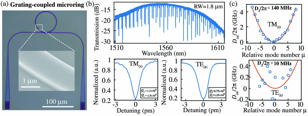
    Fig. 2. (a) Optical micrograph of a 36-μm-radius SiC microring with grating input and output. The inset shows the scanning electron micrograph for one section of the ring waveguide, which exhibits smooth sidewalls and >80  deg sidewall angles. The access waveguide widths are set to be near 800 nm and 1000 nm for efficient coupling to TM00 and TE00 modes, respectively. (b) (top) Exemplary transmission of a grating-coupled microring resonator, with a typical insertion loss around 5–7 dB per grating and a 3 dB coupling bandwidth around 60–80 nm. The grating period is optimized to center the peak efficiency near the wavelength of 1550 nm. (bottom) Representative resonances with normalized transmission for TM00 and TE00 modes, both with intrinsic Q above 1 million (QL and Qi stand for the loaded Q and intrinsic Q, respectively). (c) Dispersion characterization of TM00 and TE00 mode families, displaying an estimated second-order dispersion (D2/2π) near 140 MHz and 10 MHz, respectively. The deviation of the data points (circles) from the fitting curve (solid line) is primarily due to the measurement uncertainties in determining the resonance frequency of each mode, which is estimated to be near 100–200 MHz (notice that the linewidth of each resonance is approximately 300 MHz).
    (a) Nonlinear transmission of the TM00 mode with an input power near 200 mW. The resonance is broadened due to the thermo-optic and Kerr effects. The SiC microring has a width of 2.0 μm. (b) Comb spectra corresponding to the chaotic modulation-instability (MI) state and coherent soliton-crystal (SC) state. These two different states are generated by slowly varying the laser detunings, with their respective positions marked in (a). (c) Coherence characterization by filtering out one of the comb lines [marked by circles in (b)] and measuring its beat-note signal with an auxiliary narrow-linewidth laser tuned into similar wavelengths: (top) the MI comb state shows multiple RF peaks while (bottom) the SC state shows a single RF peak that shifts with the wavelength of the auxiliary tunable laser.
    Fig. 3. (a) Nonlinear transmission of the TM00 mode with an input power near 200 mW. The resonance is broadened due to the thermo-optic and Kerr effects. The SiC microring has a width of 2.0 μm. (b) Comb spectra corresponding to the chaotic modulation-instability (MI) state and coherent soliton-crystal (SC) state. These two different states are generated by slowly varying the laser detunings, with their respective positions marked in (a). (c) Coherence characterization by filtering out one of the comb lines [marked by circles in (b)] and measuring its beat-note signal with an auxiliary narrow-linewidth laser tuned into similar wavelengths: (top) the MI comb state shows multiple RF peaks while (bottom) the SC state shows a single RF peak that shifts with the wavelength of the auxiliary tunable laser.
    Comb spectra for the TE00 modes of 36-μm-radius SiC microrings with varied ring widths and an estimated on-chip power of 120 mW. The orange and light blue colors indicate the data collected from two different optical spectrum analyzers given the wide wavelength range. The inset in the top figure shows the experimental setup for broadband comb measurement. The input is a continuous-wave signal near the wavelength of 1550 nm coupled from a fiber V-groove array to the waveguide through a grating coupler, while the broadband output is routed to the polished facet and collected using a lensed fiber (butt coupling). For RW=1.8 μm, a secondary mode family appears beyond wavelengths of 2200 nm (see the inset in the third figure from top), which is likely caused by accidental phase matching for the frequency mixing process between the TE00 mode and a higher-order waveguide mode at these wavelengths. The spectral bandwidth corresponding to ring widths of 1.8 μm and 1.9 μm is estimated to be larger than 150 THz.
    Fig. 4. Comb spectra for the TE00 modes of 36-μm-radius SiC microrings with varied ring widths and an estimated on-chip power of 120 mW. The orange and light blue colors indicate the data collected from two different optical spectrum analyzers given the wide wavelength range. The inset in the top figure shows the experimental setup for broadband comb measurement. The input is a continuous-wave signal near the wavelength of 1550 nm coupled from a fiber V-groove array to the waveguide through a grating coupler, while the broadband output is routed to the polished facet and collected using a lensed fiber (butt coupling). For RW=1.8  μm, a secondary mode family appears beyond wavelengths of 2200 nm (see the inset in the third figure from top), which is likely caused by accidental phase matching for the frequency mixing process between the TE00 mode and a higher-order waveguide mode at these wavelengths. The spectral bandwidth corresponding to ring widths of 1.8 μm and 1.9 μm is estimated to be larger than 150 THz.
    Lutong Cai, Jingwei Li, Ruixuan Wang, Qing Li. Octave-spanning microcomb generation in 4H-silicon-carbide-on-insulator photonics platform[J]. Photonics Research, 2022, 10(4): 870
    Download Citation