
Cheng Feng, Stefan Preussler, Thomas Schneider, "Sharp tunable and additional noise-free optical filter based on Brillouin losses," Photonics Res. 6, 132 (2018)
- Photonics Research
- Vol. 6, Issue 2, 132 (2018)
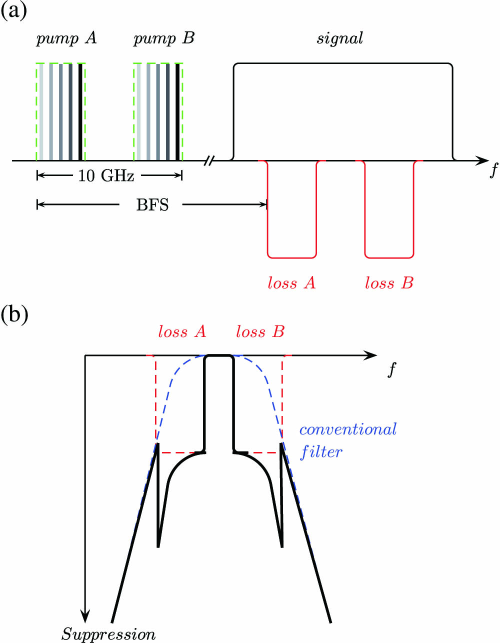
Fig. 1. (a) Principle of the proposed filter based on SBS losses. Black solid line, broad input signal; BFS, Brillouin frequency shift. (b) Overall filter profile of SBS loss-based filter with a conventional optical filter. Blue dashed line, filter profile of conventional filter; red dashed line, SBS losses; black solid line, overall filter profile.
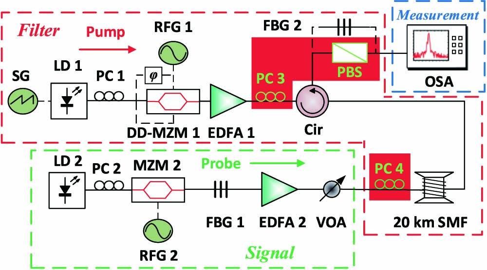
Fig. 2. Experimental setup. SG, signal generator; LD, laser diode; PC, polarization controller; RFG, radio frequency generator; DD-MZM, dual-drive Mach–Zehnder modulator; EDFA, erbium-doped fiber amplifier; Cir, circulator; FBG, fiber Bragg grating; VOA, variable optical attenuator; SMF, single-mode fiber; PBS, polarization beam splitter; OSA, optical spectrum analyzer.
Fig. 3. Pump signal for the filter pass bandwidth of (a) 500 MHz, (b) 3.7 GHz, (c) 7.1 GHz, and (d) 9.5 GHz.
Fig. 4. Filter profile for fixed center frequency and filter pass bandwidths of 500 MHz (black), 3.7 GHz (red), 7.1 GHz (blue), and 9.5 GHz (pink) with polarization pulling.
Fig. 5. Filter profile for tunable center frequency and filter pass bandwidths of 500 MHz (black), 3.7 GHz (red), 7.1 GHz (blue), and 9.5 GHz (pink).
Fig. 6. Heterodyne detection of the filtered signal with a local oscillator within the pass band of (a) the SBS loss-based filter and (b) the SBS gain-based filter. Insets (i) and (ii) show the peak signal and the pump spectrum, respectively.


Set citation alerts for the article
Please enter your email address

© Copyright 2018-2021 | Chinese Laser Press. All Rights Reserved 沪ICP备15018463号-20