Abstract
In this paper, we propose an additional noise-free, independent center frequency and bandwidth tunable optical filter based on stimulated Brillouin scattering (SBS) losses. By suppressing the out-of-band signal with two broadened symmetric SBS losses, tunable pass bandwidths from 500 MHz to 9.5 GHz and the independent center frequency tunability are demonstrated. Considering the limited SBS interaction in the center frequency range, a flat-top response with minimum 0.3 dB ripple is achieved. Assisted by the extra suppression from polarization pulling, a maximum selectivity of 20 dB and an ultrahigh roll-off are reached. A gain-based SBS filter adds noise to the filtered signal. However, for our proposed filter setup, no additional noise is detected due to the transparency in the passband. Considering the wide independent bandwidth and center frequency tunability, flat-top response, and low-noise characteristic, our proposed filter can be perfectly used as a supplement of most commercialized conventional tunable optical single bandpass filters, whose minimum bandwidth is limited by 10 GHz.1. INTRODUCTION
Over the past decades, optical filters have played an increasingly important role in different applications. Due to their excellent performance of low loss, immunity to electromagnetic interference, tunability, and reconfigurability, optical filters are widely used for channel selection in dense wavelength-division-multiplexed (DWDM) networks [1,2], microwave-photonic signal processing [3], and spectroscopy [4]. Several mature techniques such as fiber Bragg gratings (FBG), Mach–Zehnder interferometers (MZI), and Fabry–Perot interferometers (FPI) are already available for realizing passive optical filters. However, for an ideal signal bandpass filter (BPF) with sharp edges, flat-top response, and an independent wide center frequency and bandwidth tuning range, each of them still has its own disadvantage. To be specific, despite the already commercialized FBG technique, limiting the bandwidth well below 10 GHz while maintaining the wide center frequency and bandwidth tunability is still challenging. Although MZI- and FPI-based filters can easily achieve a narrow bandwidth in the MHz range, instead of a single passband, they have periodic passbands [2].
As an interesting alternative, stimulated Brillouin scattering (SBS) gain-based filters have been intensively studied in the past few years. SBS owns striking advantages, such as low threshold, high gain, and an ultra-narrow natural bandwidth of , which can even be reduced down to with specific techniques [5–7]. All these properties are ideal for an application of SBS as a tunable BPF [8–10]. The investigation of SBS in BPF ranges from the enhancement of an independent tunability of the center frequency and bandwidth through direct modulation of the pump laser [11–13], multitones [14], and sweeping signal [15] external modulation, via pursuing a higher selectivity using polarization pulling (PP) [16,17], multistage configuration [18], a rectangular flat-top response by modulation feedback compensation [14,15] to polarization-independent SBS filters [15,19], even the filter profile can be arbitrarily shaped by direct modulation of the pump [20]. However, as a disadvantage of almost every amplification mechanism, SBS gain also introduces amplified spontaneous emission (ASE) noise [21,22]. The noise level is relatively high at a high pump power, which is unfortunately uncompromised with a high filter selectivity [18].
In this paper, we propose a novel method to demonstrate an optical filter based on SBS losses instead of gain. Contrary to previously proposed SBS-based filters, the passband of our filter is free from any additional noise. By suppressing the out-of-band signal with two broadened symmetric SBS losses, the pass bandwidth can be tuned from 500 MHz to 9.5 GHz by properly broadening the pump spectrum and choosing the proper frequency separation between the pump waves. The minimum achievable bandwidth corresponds to the natural SBS bandwidth (10–30 MHz). However, due to experimental restrictions, only 500 MHz is demonstrated in this paper. An independent bandwidth and center frequency tunability are also demonstrated. By applying the PP technique of SBS [23], the maximum selectivity of our proposed filter is enhanced to more than 20 dB; therefore, sharp filter edges with ultrahigh roll-off are achieved. Because the passband of the filter is not influenced by the SBS process, no additional noise is added to the signal, and a flat-top response with minimum 0.3 dB ripple is easy to achieve. A noise measurement verifies that our proposed filter can provide filtering with no additional noise, while a maximum 5 dB noise pedestal is detected for an SBS gain-based filter at the same pump power. Considering the wide tunability, flat-top response, and low-noise characteristic, our proposed filter is able to work as an optical filter in cooperation with most commercialized conventional filters, whose minimum bandwidth is limited by 10 GHz.
Sign up for Photonics Research TOC. Get the latest issue of Photonics Research delivered right to you!Sign up now
2. PRINCIPLE
Stimulated Brillouin scattering in an optical fiber can be classically described as an interaction between a pump wave and a counterpropagating, frequency-downshifted Stokes wave via an acoustic wave [24]. Due to the electrostriction in the fiber and the conservation of energy, the moving acoustic wave transfers energy from the pump to the counterpropagating, frequency-downshifted probe wave, producing the SBS gain. However, not only energy but also ASE noise will be simultaneously transferred to the probe wave. On the other side, if the frequency is Brillouin upshifted, the pump receives energy from the probe wave, producing the SBS loss.
In order to avoid ASE noise from the SBS gain, our proposed filter is based on the SBS loss mechanism. The basic principle of the proposed filter is depicted in Fig. 1. The filter passband is the transparency region between two broadened losses with an overall frequency bandwidth of 10 GHz. In order to circumvent the problem of four-wave-mixing due to multitones [25], two pump waves (pumps A and B), produced by the same source, are broadened by a direct modulation with the same sweeping signal, whose sweeping periodicity is within the signal propagation time in the fiber [15]. Due to the broadened pump waves, the broad input signal is suppressed symmetrically on both sides by the broadened SBS losses (losses A and B) in the frequency range of the Brillouin upshift, while the center frequency part stays transparent. All other out-of-range frequency components on both sides of the losses can be well suppressed with the assistance of a conventional optical filter, as shown with the blue dashed line in Fig. 1(b). Because the signal in the filter passband remains in the maximum transmission of the conventional filter, it is neither affected by the SBS process nor distorted by the conventional filter, and no additional noise is added. Considering the Gaussian-shaped filter profile of most of the conventional optical filters (as shown in Fig. 1) with high rejections on both sides and flat-top response in the vicinity of the center frequency, the suppression of the spectral components far away from the center is higher than close to the passband of the SBS filter, as shown in Fig. 1(b).
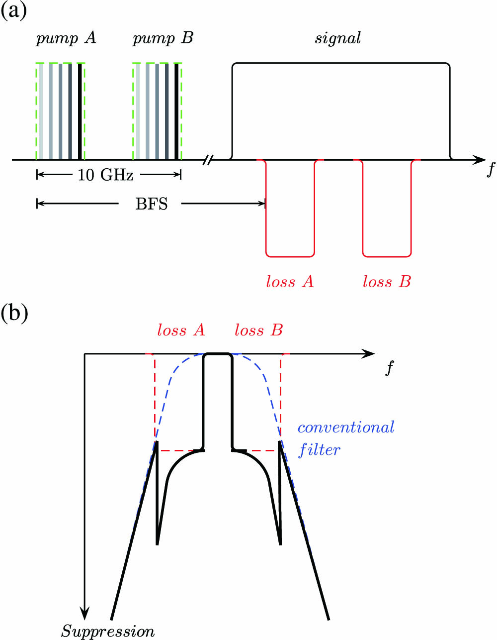
Figure 1.(a) Principle of the proposed filter based on SBS losses. Black solid line, broad input signal; BFS, Brillouin frequency shift. (b) Overall filter profile of SBS loss-based filter with a conventional optical filter. Blue dashed line, filter profile of conventional filter; red dashed line, SBS losses; black solid line, overall filter profile.
By carefully controlling the frequency separation between the two pumps and the broadened linewidth of the pump waves (which depends on the amplitude of the sweeping signal), the total pump range and thereby the loss range can be well controlled in a frequency range of about 10 GHz. In order to suppress all unwanted components outside this range, the proposed filter has to be used in combination with a conventional optical filter with a bandwidth from 10 to 30 GHz. In this way, the simultaneous SBS gain will also be eliminated. By changing the pump frequency and the amplitude of the sweeping signal, the center frequency and the bandwidth of the filter can be tuned arbitrarily and independently. Due to the transparency in the passband, a flat-top response and low-noise characteristic are easy to achieve.
3. EXPERIMENTAL SETUP
The experimental setup of our proposed filter is illustrated in Fig. 2. The red dashed box illustrates the actual setup for the filter, and the green dashed box is necessary for the probe signal generation, which is measured by an optical spectrum analyzer (OSA, blue dashed box). The filter shape is generated by a direct modulation of a distributed feedback (DFB) laser diode (LD 1) operating at with a 50 kHz ramp sweeping signal and a following separation of the two losses by a sinusoidal modulation of a dual-drive Mach–Zehnder modulator (DD-MZM 1). The broadened pump linewidth depends on the amplitude of the sweeping signal from the signal generator (SG). The DD-MZM 1 provides an external optical single-sideband (OSSB) modulation driven by a radio frequency (RF) signal from a radio frequency generator (RFG 1). With a proper driving bias voltage and phase shift, one of the sidebands is suppressed, while the carrier and another unsuppressed sideband have the same power [26]. The modulation frequencies of RFG 1 and SG are selected so that the broadened carrier, unsuppressed sideband, and the frequency separation between them cover a frequency range of approximately 10 GHz (as shown in Fig. 1). A high-power erbium-doped fiber amplifier (EDFA 1) in the pump branch amplifies this pump signal at constant power mode and emits via a circulator (Cir) into the 20 km long single-mode fiber (SMF). The dual-isolation circulator offers a directivity of more than 60 dB, which prevents the filter profile measurement from the Rayleigh scattering, even when the pump power is amplified to a high level. The probe signal for measuring the filter bandwidth is injected from the other side into the fiber. Thus, another LD (LD 2), which operates at a 20 GHz frequency upshift to LD1, is modulated by RFG 2 and works in the carrier-suppressed mode. The lower frequency sideband from the MZM 2 is filtered out by a fiber Bragg grating (FBG 1) and used as the probe signal. This probe signal can be scanned in a wide range in order to measure the whole filter bandwidth. A higher probe power ensures a higher signal-to-noise ratio (SNR). However, the probe power must be below the threshold of any nonlinear effects in the fiber. Therefore, in our experiments, EDFA 2 and a variable optical attenuator (VOA) are utilized to ensure the probe power to be 5 dBm. Because the Brillouin frequency shift (BFS) of the 20 km SMF in the setup is 10.861 GHz, a scanning range of RFG 2 from 6 GHz to 20 GHz every 20 MHz is enough to get the filter profile from the peak value in an OSA. Note that, FBG 2 is only connected to the setup during the noise measurement discussed in Section 5; therefore, any possible Rayleigh scattering of the pump wave and other frequency components are ensured to be blocked.

Figure 2.Experimental setup. SG, signal generator; LD, laser diode; PC, polarization controller; RFG, radio frequency generator; DD-MZM, dual-drive Mach–Zehnder modulator; EDFA, erbium-doped fiber amplifier; Cir, circulator; FBG, fiber Bragg grating; VOA, variable optical attenuator; SMF, single-mode fiber; PBS, polarization beam splitter; OSA, optical spectrum analyzer.
In order to show the selectivity enhancement of the proposed filter through polarization pulling (PP), experiments with a variable pass bandwidth with PP components (highlighted in red in Fig. 2) are carried out. The polarization of the probe wave is controlled through a polarization controller (PC 4), so that the output power in the passband through the polarization beam splitter (PBS) is maximized, while the polarization of the pump wave is controlled through PC 3, so that the output power in the stop band through the same port of the PBS is close to a minimum. Considering the output in the stop band will suffer from not only the attenuation through SBS losses but also extra polarization suppression, enhancement of the selectivity is achieved [16,23].
Figure 3 illustrates the pump signal after EDFA 1 measured by a heterodyne multiplication with a local oscillator (LO, not shown in Fig. 2) in a photodiode (PD, Finisar XPDV21X0R 50 GHz Photodetector). By fixing the direct modulation frequency and increasing the amplitude from SG, the pump bandwidth from LD 1 increases from 0.25 GHz via 1.45 GHz and 3.15 GHz to 5.48 GHz. The pump powers from the EDFA 1 are 17, 25, 28, and 30 dBm, correspondingly. By a proper protective attenuation with a VOA before the PD, the detected amplitudes can be manually adjusted to almost the same value (as shown in Fig. 3). The unflatness of the pump wave is due to the parasitic effect [27]. However, it has no influence on the filter passband.
Figure 3.Pump signal for the filter pass bandwidth of (a) 500 MHz, (b) 3.7 GHz, (c) 7.1 GHz, and (d) 9.5 GHz.
As shown in Fig. 4, filter pass bandwidths from 9.5 GHz via 7.3 GHz and 3.7 GHz to 500 MHz with ripples as low as 0.3 dB are achieved. Because the passband is left transparent between two losses, this ripple might result mainly from the measurement error of the OSA and the output power instability of the probe LD (LD 2). However, due to the not-perfect modulation of the pump waves producing the losses, the pump profile is not a perfect rectangle (as shown in Fig. 3). Thus, at the edges of the filter passband, these losses have an influence. This edge effect leads to a finite roll-off. With a pre-compensation of the direct modulation of the LD current, as demonstrated in Ref. [20], filter bandwidth down to the natural bandwidth of SBS and an edge effect limited to this range might be possible.
Figure 4.Filter profile for fixed center frequency and filter pass bandwidths of 500 MHz (black), 3.7 GHz (red), 7.1 GHz (blue), and 9.5 GHz (pink) with polarization pulling.
As can be seen, although the signal amplitude in the passband is almost independent of the filter bandwidth, the selectivity is bandwidth dependent. Generally, the narrower the pass bandwidth, i.e., the broader the pump linewidth, the more difficult it is to obtain a high selectivity, even under the assistance of PP, which shows an accordance with the conclusions in gain mechanism [11,15,18,28]. To be specific, a selectivity of more than 20 dB is achieved for a bandwidth of 9.5 GHz with PP for only 17 dBm pump power. In contrast, even with a pump power of 30 dBm, for 500 MHz a selectivity of only 11 dB can be achieved with PP. We attribute the asymmetry of the losses, which appears especially close to the passband, to the asymmetry of the pump wave. However, by an appropriate pre-compensation this could be avoided.
4. CENTER FREQUENCY AND BANDWIDTH TUNABILITY
In principle, the filter center frequency is governed by the pump frequency (which further depends on the temperature of LD 1), while the filter bandwidth is dependent on the RF signal frequency from RFG 1 and the amplitude of the direct modulation signal from SG. Therefore, an independent center frequency and bandwidth tuning can be achieved and is demonstrated, as shown in Fig. 5. The maximum center frequency tuning range can be as wide as the working frequency range of the LDs in the setup.
Figure 5.Filter profile for tunable center frequency and filter pass bandwidths of 500 MHz (black), 3.7 GHz (red), 7.1 GHz (blue), and 9.5 GHz (pink).
5. NOISE MEASUREMENT
Besides the rectangular shape and the narrow bandwidth, the special advantage of the proposed filter is the transparency and low noise in the passband. The noise was measured by a heterodyne detection of the probe signal with a local oscillator (LO) inside the filter passband [18] for an SBS gain and loss-based filter. In principle, the same setup in Fig. 2 with the frequency of LD 2 downshifted for to LD 1 can be directly used as an SBS gain-based filter. In order to make a fair comparison, the pass bandwidths (2 GHz) and the selectivity for both cases are set to be the same, i.e., the SBS gain equals the SBS loss [ as measured in Fig. 6(b)]. Considering the different mechanism of Brillouin gain and loss, a different probe power is applied ( for the gain filter, while for the loss case it remains 5 dBm) in order to satisfy this condition under the same 17 dBm pump power. As shown in Fig. 6(a), the probe heterodyne signal within the passband of a loss-based filter is overlapped for the case when the pump is on and off, indicating a full transparency of the filter passband. However, as depicted in inset (i) of Fig. 6(b), despite the same SBS gain, an evident pump-spectrum-like [shown in inset (ii) of Fig. 6(b)] noise pedestal with maximum 5 dB difference is detected when the pump is on, while it vanishes when the pump is off, which is in good agreement with the noise measurement of a gain-based filter [18]. In order to achieve the same selectivity, the frequency of the probe signal is aligned at the edge of the Brillouin gain; therefore, the Brillouin noise pedestal is off-center to the right in Fig. 6(b).
Figure 6.Heterodyne detection of the filtered signal with a local oscillator within the pass band of (a) the SBS loss-based filter and (b) the SBS gain-based filter. Insets (i) and (ii) show the peak signal and the pump spectrum, respectively.
Furthermore, based on Fig. 6 and the definition of the noise figure as the ratio of input and output SNR of the filter, the noise figures of the gain and loss-based filter are calculated to be 2.6904 and 0.9861, respectively. For the calculation of the SNR, we have integrated the noise over the filter bandwidth, as would be done by a broadband receiver. The reason for might be a measurement error of the used electrical spectrum analyzer (ESA). As can be seen, in our case there is no additional noise, whereas the gain-based system has a noise figure of almost 3. For a multistage gain-based system, as in Ref. [18], each single stage adds noise to the signal, and the noise from the former stage will even be amplified in the next. This would not be the case for a multistage loss-based system as proposed here.
6. DISCUSSION AND CONCLUSION
Due to the not-rectangular-enough pump spectrum in our setup, the SBS interaction from the edges of the pump makes the filter profile at the edges also not perfectly rectangular; thus, the minimum demonstrated filter bandwidth is restricted to 500 MHz. However, with an appropriate pre-compensation of the pump wave [20], which produces the losses, the pump profile will be more rectangular-like; therefore, the minimum achievable bandwidth should be 10–30 MHz, the natural bandwidth of SBS. Furthermore, the selectivity of the filter might be further enhanced, by a multistage configuration [18] or a phase-modulated probe wave [29], which could lead to a much sharper edge with much higher roll-off.
In conclusion, we have proposed a novel tunable optical filter based on SBS losses with no additional noise. With the out-of-band signals being suppressed by two symmetric broadened SBS losses, the pass bandwidth can be well controlled arbitrarily. An independent tunability of the center frequency and bandwidth ranging from 500 MHz to 9.5 GHz is demonstrated. Assisted by the polarization pulling, the maximum selectivity of our proposed filter is enhanced to more than 20 dB. This simple idea of the filter enables integration on a silicon photonics platform [30,31] or -based chips [32]. Because the passband is left transparent, the proposed active filter has successfully overcome the ASE noise, which is the main disadvantage of well performed SBS gain-based filters. Considering the sharp edges, flat-top response, low-noise performance, independent bandwidth, and center frequency tunability within 10 GHz range, the proposed filter can be used in combination with conventional filters, thus enabling a narrow-bandwidth rectangular filter.
References
[1] J. Capmany, B. Ortega, D. Pastor. A tutorial on microwave photonic filters. J. Lightwave Technol., 24, 201-229(2006).
[2] D. Sadot, E. Boimovich. Tunable optical filters for dense WDM networks. IEEE Commun. Mag., 36, 50-55(1998).
[3] J. Capmany, B. Ortega, D. Pastor, S. Sales. Discrete-time optical processing of microwave signals. J. Lightwave Technol., 23, 702-723(2005).
[4] N. Gat. Imaging spectroscopy using tunable filters: a review. Proc. SPIE, 4056, 50-64(2000).
[5] S. Preussler, A. Wiatrek, K. Jamshidi, T. Schneider. Brillouin scattering gain bandwidth reduction down to 3.4 MHz. Opt. Express, 19, 8565-8570(2011).
[6] S. Preussler, T. Schneider. Stimulated Brillouin scattering gain bandwidth reduction and applications in microwave photonics and optical signal processing. Opt. Eng., 55, 031110(2016).
[7] A. Wiatrek, S. Preussler, K. Jamshidi, T. Schneider. Frequency domain aperture for the gain bandwidth reduction of stimulated Brillouin scattering. Opt. Lett., 37, 930-932(2012).
[8] W. Zhang, R. A. Minasian. Ultrawide tunable microwave photonic notch filter based on stimulated Brillouin scattering. IEEE Photon. Technol. Lett., 24, 1182-1184(2012).
[9] W. Zhang, R. A. Minasian. Widely tunable single-passband microwave photonic filter based on stimulated Brillouin scattering. IEEE Photon. Technol. Lett., 23, 1775-1777(2011).
[10] R. Tao, X. Feng, Y. Cao, Z. Li, B. Guan. Widely tunable single bandpass microwave photonic filter based on phase modulation and stimulated Brillouin scattering. IEEE Photon. Technol. Lett., 24, 1097-1099(2012).
[11] Z. Zhu, A. M. Dawes, D. J. Gauthier, L. Zhang, A. E. Willner. 12-GHz-bandwidth SBS slow light in optical fibers. Optical Fiber Communication Conference and Exposition and the National Fiber Optic Engineers Conference, PDP1(2006).
[12] A. Zadok, A. Eyal, M. Tur. Gigahertz-wide optically reconfigurable filters using stimulated Brillouin scattering. J. Lightwave Technol., 25, 2168-2174(2007).
[13] T. Tanemura, Y. Takushima, K. Kikuchi. Narrowband optical filter, with a variable transmission spectrum, using stimulated Brillouin scattering in optical fiber. Opt. Lett., 27, 1552-1554(2002).
[14] W. Wei, L. Yi, Y. Jaouën, W. Hu. Bandwidth-tunable narrowband rectangular optical filter based on stimulated Brillouin scattering in optical fiber. Opt. Express, 22, 23249-23260(2014).
[15] L. Yi, W. Wei, Y. Jaouën, M. Shi, B. Han, M. Morvan, W. Hu. Polarization-independent rectangular microwave photonic filter based on stimulated Brillouin scattering. J. Lightwave Technol., 34, 669-675(2016).
[16] A. Wise, M. Tur, A. Zadok. Sharp tunable optical filters based on the polarization attributes of stimulated Brillouin scattering. Opt. Express, 19, 21945-21955(2011).
[17] Y. Stern, K. Zhong, T. Schneider, R. Zhang, Y. Ben-Ezra, M. Tur, A. Zadok. Tunable sharp and highly selective microwave-photonic band-pass filters based on stimulated Brillouin scattering. Photon. Res., 2, B18-B25(2014).
[18] W. Wei, L. Yi, Y. Jaouën, M. Morvan, W. Hu. Brillouin rectangular optical filter with improved selectivity and noise performance. IEEE Photon. Technol. Lett., 27, 1593-1596(2015).
[19] C. Xing, C. Ke, K. Zhang, Z. Guo, Y. Zhong, D. Liu. Polarization- and wavelength-independent SBS-based filters for high resolution optical spectrum measurement. Opt. Express, 25, 20969-20982(2017).
[20] W. Wei, L. Yi, Y. Jaouën, W. Hu. Arbitrary-shaped Brillouin microwave photonic filter by manipulating a directly modulated pump. Opt. Lett., 42, 4083-4086(2017).
[21] M. F. Ferreira, J. F. Rocha, J. L. Pinto. Analysis of the gain and noise characteristics of fibre Brillouin amplifiers. Opt. Quantum Electron., 26, 35-44(1994).
[22] M. Choi, I. C. Mayorga, S. Preussler, T. Schneider. Investigation of gain dependent relative intensity noise in fiber Brillouin amplification. J. Lightwave Technol., 34, 3930-3936(2016).
[23] A. Zadok, E. Zilka, A. Eyal, L. Thévenaz, M. Tur. Vector analysis of stimulated Brillouin scattering amplification in standard single-mode fibers. Opt. Express, 16, 21692-21707(2008).
[24] A. Kobyakov, M. Sauer, D. Chowdhury. Stimulated Brillouin scattering in optical fibers. Adv. Opt. Photon., 2, 1-59(2010).
[25] W. Wei, L. Yi, Y. Jaouën, M. Morvan, W. Hu. Ultra-selective flexible add and drop multiplexer using rectangular optical filters based on stimulated Brillouin scattering. Opt. Express, 23, 19010-19021(2015).
[26] M. A. Soto, M. Alem, M. Amin Shoaie, A. Vedadi, C.-S. Brès, L. Thévenaz, T. Schneider. Optical sinc-shaped Nyquist pulses of exceptional quality. Nat. Commun., 4, 2898(2013).
[27] R. S. Tucker. High-speed modulation of semiconductor lasers. J. Lightwave Technol., 3, 1180-1192(1985).
[28] K. Y. Song, K. Hotate. 25 GHz bandwidth Brillouin slow light in optical fibers. Opt. Lett., 32, 217-219(2007).
[29] A. Choudhary, Y. Liu, B. Morrison, I. Aryanfar, D. Marpaung, B. J. Eggleton, K. Vu, D. Y. Choi, P. Ma, S. Madden. On-chip EIT-like RF photonic signal processor. IEEE International Topical Meeting on Microwave Photonics (MWP), 317-320(2016).
[30] E. A. Kittlaus, N. T. Otterstrom, P. T. Rakich. On-chip inter-modal Brillouin scattering. Nat. Commun., 8, 15819(2017).
[31] E. A. Kittlaus, H. Shin, P. T. Rakich. Large Brillouin amplification in silicon. Nat. Photonics, 10, 463-467(2016).
[32] R. Pant, C. G. Poulton, D. Choi, H. Mcfarlane, S. Hile, E. Li, L. Thévenaz, B. Luther-Davies, S. J. Madden, B. J. Eggleton. On-chip stimulated Brillouin scattering. Opt. Express, 19, 8285-8290(2011).


