
Changkun Feng, Yonggui Zhang, Honghao Ma, Hui Li, Lishuang Feng, "Improving long-term temperature bias stability of an integrated optical gyroscope employing a Si3N4 resonator," Photonics Res. 10, 1661 (2022)
- Photonics Research
- Vol. 10, Issue 7, 1661 (2022)
Abstract
1. INTRODUCTION
With the development of integrated photonics, high-performance waveguide resonators have found wide applications, such as in ultranarrow linewidth lasers [1–3], optical frequency combs [4–6], optical gyroscopes [7], and biosensors [8,9], and are playing an increasingly important role. At the same time, resonant integrated optical gyroscopes (RIOGs) based on waveguide resonators are becoming more accurate, smaller in size, and more highly integrated [10,11]. At present, low-cost micro-electro-mechanical system (MEMS) gyroscopes are commonly used in the market, and the long-term bias stability is greater than about 10°/h, which belongs to the category of medium and low precision. However, compared with RIOG, MEMS-based gyroscopes are less resistant to shock and vibration, further limiting their applications. The RIOGs employ monolithic integration or hybrid integration technology to integrate part, or all, of the light source, modulator, beam splitter, detector, and other devices on a chip to realize micro-systemization. RIOGs measure rotational angular velocity by detecting the resonant frequency difference caused by the Sagnac effect [12]. Its core component is the waveguide resonator, and the design and manufacture of high-performance integrated optical resonators is the key to improving the performance of the RIOG.
The sensitivity of the RIOG is a function of the quality factor (
Many materials can be used to make a resonator, such as polymers [20,21], silica [22], and
Sign up for Photonics Research TOC. Get the latest issue of Photonics Research delivered right to you!Sign up now
At present, many research institutions have conducted a lot of research on
The
In this paper, a transmissive
2. THEORETICAL SIMULATION
The sensitivity of an RIOG can be defined as [37]
Figure 1 shows the relationship between the sensitivity and coupling coefficient for gyroscopes under different waveguide propagation loss conditions when the resonator diameter is 35 mm. When the propagation loss is lower, the sensitivity of the gyroscope (obtained at the optimal value of the coupling coefficient) is higher.
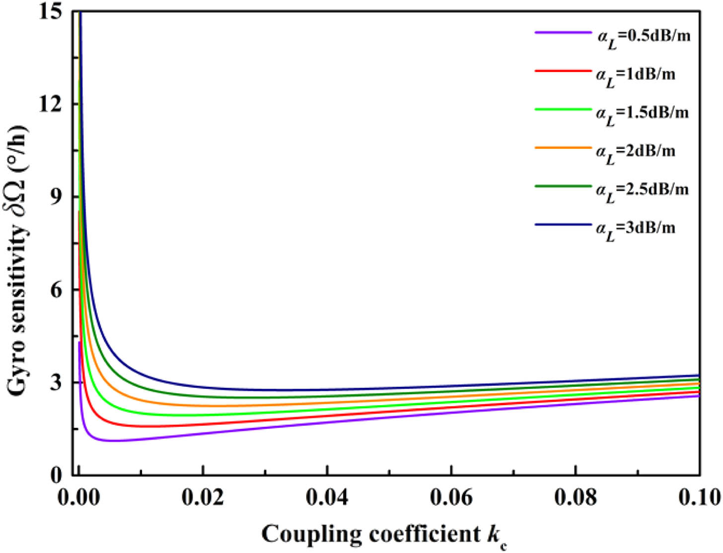
Figure 1.Relationship between gyroscope sensitivity and coupling coefficient at different waveguide propagation losses.
As can be seen from Fig. 2, propagation loss will reduce the peak value of the resonant curve of the resonator, and the transmittance of the resonator will decrease. In addition, as the peak value of the resonant curve decreases, the full width at half-maximum (
![]()
Figure 2.Variation of the peak value of the resonance curve at different propagation losses.
The single-polarization resonators can excite only one mode, thus suppressing the temperature-dependent polarization noise of the RIOG. Also, the polarization model of the resonator has been established in our previous work. Based on Eqs. (3)–(5) [19], we can see that the polarization extinction ratio of incident light is related to factors such as the polarization-to-axis angle at the input end of the waveguide, the polarization cross talk of the resonator coupler, and the polarization-dependent loss, all of which affect the resonator performance:
When the polarization axis of the incident light deviates from the TE or TM mode directions of the waveguide, the primary and secondary polarization states of the resonator will be excited simultaneously. In addition, when the light passes through the coupler, polarization cross talk will occur in the TE and TM mode directions due to the influence of scattering of the medium, non-ideal waveguide geometry, internal stress, and other factors. Therefore, even if the input light is ideally linearly polarized and is strictly aligned with a certain polarization mode of the waveguide, due to the polarization cross talk of the actual coupler, there will still be light with the orthogonal polarization in the resonator. As long as the polarization cross talk is not zero, there will be alternating destructive and constructive interference, as shown in Fig. 3(a).
![]()
Figure 3.(a) According to the polarization model [19] calculated three-dimensional resonance curve output at different birefringences;
We assume that the waveguide coupler has no polarization cross talk if the polarization axis of the incident light has a certain angle with the TE mode direction, such that the energy distributions of the input light in the TE and the TM mode directions are different. The factors affecting the energy distribution of the incident light in the TE and the TM modes are equivalent to the polarization axis error. Obviously, the larger the polarization axis error, the larger the peak of the sub-polarization state, as shown in Fig. 3(b).
However, as Fig. 3(c) shows, if the resonator has sufficient polarization-dependent loss, then even in the presence of polarization axis error and coupler polarization cross talk, only one mode is excited inside the resonator. Therefore, having sufficient polarization-dependent loss is the key to realizing a single-polarization resonator.
3.
In this paper, the structure of the
![]()
Figure 4.(a) Structure diagram of the
The low-loss and single-polarization
To further reduce propagation losses, we need to understand the characteristics of the film and determine which factors cause losses. As Eq. (6) shows, the three types of losses in the optical waveguide are surface scattering losses, absorption losses, and radiation losses. The scattering is the main source of propagation loss and is mainly caused by the surface roughness of the waveguide. Since the waveguide surface will never be completely smooth, the scattering loss will always exist. Absorption losses are mainly caused by the residual hydrogen during the deposition of the waveguide. In contrast, radiation losses are generally low, and occur when the bending radius is small.
As Figs. 4(b) and 4(c) show, for
Figure 5 shows the photograph with rear illumination inside the
![]()
Figure 5.Infrared photograph of the
4.
Figure 6 shows the relative test curve of the
![]()
Figure 6.Relative test curve of the
According to Eq. (3), in a waveguide resonator without polarization-dependent loss, when the polarization state of incident light is at a certain angle with the main polarization state of the resonator, the TE and TM polarization states will be excited simultaneously, and the relative position between the two resonant peaks will change with the change of waveguide birefringence. However, for the waveguide resonator with high polarization-dependent loss, the secondary polarization state in the incident light will be effectively suppressed. Therefore, the obtained sweep curve contains only one resonance peak, and the peak value will not fluctuate significantly with the change of waveguide birefringence.
To test this latter contention, we studied the polarization and temperature performance of the
Once again, the output light at the transmission end of the waveguide resonator was converted into a voltage signal by a PD which was displayed on an OSC. Finally, to measure the temperature performance of the
![]()
Figure 7.Measured resonance curves at different temperatures: (a)
5. EXPERIMENTAL RESULT OF RIOG
Figure 8 shows the RIOG measurement system based on a
![]()
Figure 8.RIOG measurement system based on the
When the
![]()
Figure 9.Measurement results of the RIOG based on the
6. CONCLUSION
In summary, a high-performance
Acknowledgment
Acknowledgment. The authors thank LioniX International (LXI) for their assistance in fabricating Si3N4 waveguides.
References
[1] T. Kessler, C. Hagemann, C. Grebing, T. Legero, U. Sterr, F. Riehle, M. J. Martin, L. Chen, J. Ye. A sub-40-mHz-linewidth laser based on a silicon single crystal optical cavity. Nat. Photonics, 6, 687-692(2012).
[2] S. Gundavarapu, G. M. Brodnik, M. Puckett, T. Huffman, D. Bose, R. Behunin, J. F. Wu, T. Q. Qiu, C. Pinho, N. Chauhan, J. Nohava, P. T. Rakich, K. D. Nelson, M. Salit, D. J. Blumenthal. Sub-hertz fundamental linewidth photonic integrated Brillouin laser. Nat. Photonics, 13, 60-67(2019).
[3] L. Stern, W. Zhang, D. Carlson, D. Popp, Z. Newman, S. Kang, J. Kitching, S. Papp. Ultranarrow linewidth photonic-atomic laser. Laser Photonics Rev., 14, 1900293(2019).
[4] P. Del’Haye, A. Schliesser, O. Arcizet, T. Wilkins, R. Holzwarth, T. J. Kippenberg. Optical frequency comb generation from a monolithic microresonator. Nature, 450, 1214-1217(2007).
[5] T. J. Kippenberg, A. L. Gaeta, M. Lipson, M. L. Gorodetsky. Dissipative Kerr solitons in optical microresonators. Science, 361, eaan8083(2018).
[6] D. R. Carlson, D. D. Hickstein, L. Alex, D. Stefan, W. Daron, N. Nima, C. Ian, N. R. Newbury, S. Kartik, S. A. Diddams. Self-referenced frequency combs using high-efficiency silicon-nitride waveguides. Opt. Lett., 42, 2314-2317(2017).
[7] Y. H. Lai, M. G. Suh, Y. K. Lu, B. Shen, K. Vahala. Earth rotation measured by a chip-scale ring laser gyroscope. Nat. Photonics, 14, 345-349(2020).
[8] S. M. Lo, S. Hu, G. Gaur, Y. Kostoulas, P. M. Fauchet. Photonic crystal microring resonator for label-free biosensing. Opt. Express, 25, 7046-7054(2017).
[9] Z. Tu, D. Gao, M. Zhang, D. Zhang. High-sensitivity complex refractive index sensing based on Fano resonance in the subwavelength grating waveguide micro-ring resonator. Opt. Express, 25, 20911-20922(2017).
[10] P. P. Khial, A. D. White, A. Hajimiri. Nanophotonic optical gyroscope with reciprocal sensitivity enhancement. Nat. Photonics, 12, 671-675(2018).
[11] J. T. Geng, L. Yang, S. H. Zhao, Y. G. Zhang. Resonant micro-optical gyro based on self-injection locking. Opt. Express, 28, 32907-32915(2020).
[12] G. Sagnac. On the proof of the reality of the luminiferous aether by the experiment with a rotating interferometer. Comptes Rendus, 157, 1410-1413(1913).
[13] G. A. Sanders, M. G. Prentiss, S. Ezekiel. Passive ring resonator method for sensitive inertial rotation measurements in geophysics and relativity. Opt. Lett., 6, 569-571(1981).
[14] A. Li, W. Bogaerts. Using backscattering and backcoupling in silicon ring resonators as a new degree of design freedom. Laser Photonics Rev., 13, 1800244(2019).
[15] A. Li, V. V. Thomas, D. H. Peter, B. Peter, B. Wim. Backscattering in silicon microring resonators: a quantitative analysis. Laser Photonics Rev., 10, 420-431(2016).
[16] J. J. Wang, L. S. Feng, Q. W. Wang, H. C. Jiao, X. Wang. Suppression of backreflection error in resonator integrated optic gyro by the phase difference traversal method. Opt. Lett., 41, 1586-1589(2016).
[17] L. S. Feng, M. Lei, H. L. Liu, Y. Z. Zhou, J. J. Wang. Suppression of back-reflection noise in a resonator integrated optic gyro by hybrid phase-modulation technology. Appl. Opt., 52, 1668-1675(2013).
[18] C. K. Feng, D. K. Zhang, Y. G. Zhang, C. Qing, H. H. Ma, H. Li, L. S. Feng. Resonant integrated optical gyroscope based on Si3N4 waveguide ring resonator. Opt. Express, 29, 43875-43884(2021).
[19] C. K. Feng, D. N. Liu, H. H. Ma, C. Qing, H. Li, L. S. Feng. Design, fabrication and test of transmissive Si3N4 waveguide ring resonator. IEEE Sens. J., 21, 22918-22926(2021).
[20] J. R. Haavisto. Thin film waveguides for inertial sensors. Proc. SPIE, 412, 221-228(1983).
[21] A. Morand, C. Sanchez-Perez, P. Benech, S. Tedjini, D. Bose. Integrated optical waveguide polarizer on glass with a birefringent polymer overlay. IEEE Photonics Technol. Lett., 10, 1599-1601(1998).
[22] H. Lee, T. Chen, J. Li, K. Y. Yang, S. Jeon, O. Painter, K. J. Vahala. Chemically etched ultrahigh-
[23] B. Stern, X. C. Ji, A. Dutt, M. Lipson. Compact narrow-linewidth integrated laser based on a low-loss silicon nitride ring resonator. Opt. Lett., 42, 4541-4544(2017).
[24] E. H. Dirani, L. Youssef, C. Petit-Etienne, K. Sebastien, G. Philippe, M. Christelle, P. Erwine, S. Corrado. Ultralow-loss tightly confining Si3N4 waveguides and high-
[25] H. L. Ma, W. Y. Wang, Y. Ren, Z. H. Jin. Low-noise low-delay digital signal processor for resonant micro optic gyro. IEEE Photonics Technol. Lett., 25, 198-201(2013).
[26] Q. Wang, L. S. Feng, H. Li, X. Wang, Y. Z. Jia, D. N. Liu. Enhanced differential detection technique for the resonator integrated optic gyro. Opt. Lett., 43, 2941-2944(2018).
[27] X. C. Ji, S. Roberts, M. Corato-Zanarella, M. Lipson. Methods to achieve ultra-high quality factor silicon nitride resonators. APL Photonics, 6, 071101(2021).
[28] A. Mohanty, Q. Li, M. A. Tadayon, S. P. Roberts, G. R. Bhatt, E. Shim, X. C. Ji, J. Cardenas, S. A. Miller, A. Kepecs, M. Lipson. Reconfigurable nanophotonic silicon probes for sub-millisecond deep-brain optical stimulation. Nat. Biomed. Eng., 4, 223-231(2020).
[29] X. C. Ji, X. W. Yao, Y. Gan, A. Mohanty, M. A. Tadayon, C. P. Hendon, M. Lipson. On-chip tunable photonic delay line. APL Photonics, 4, 090803(2019).
[30] X. Ji, F. A. S. Barbosa, S. P. Roberts, A. Dutt, J. Cardenas, Y. Okawachi, A. Bryant, A. L. Gaeta, M. Lipson. Ultra-low-loss on-chip resonators with sub-milliwatt parametric oscillation threshold. Optica, 4, 619-624(2017).
[31] M. H. P. Pfeiffer, J. Q. Liu, A. S. Raja, T. Morais, B. Ghadiani, T. J. Kippenberg. Ultra-smooth silicon nitride waveguides based on the damascene reflow process: fabrication and loss origins. Optica, 5, 884-892(2018).
[32] M. Sinclair, K. Gallacher, M. Sorel, J. C. Bayley, E. McBrearty, R. W. Millar, S. Hild, D. J. Paul. 1.4 million
[33] K. Wu, A. W. Poon. Stress-released Si3N4 fabrication process for dispersion-engineered integrated silicon photonics. Opt. Express, 28, 17708-17722(2020).
[34] J. F. Bauters, M. J. R. Heck, D. D. John, J. S. Barton, C. M. Bruinink, A. Leinse, R. G. Heideman, D. J. Blumenthal, J. E. Bowers. Planar waveguides with less than 0.1 dB/m propagation loss fabricated with wafer bonding. Opt. Express, 19, 24090-24101(2011).
[35] D. T. Spencer, J. F. Bauters, M. J. R. Heck, J. E. Bowers. Integrated waveguide coupled Si3N4 resonators in the ultrahigh-
[36] M. W. Puckett, K. K. Liu, N. Chauhan, Q. C. Zhao, N. J. Jin, H. T. Cheng, J. F. Wu, R. O. Behunin, P. T. Rakich, K. D. Nelson, D. J. Blumenthal. 422 million intrinsic quality factor planar integrated all-waveguide resonator with sub-MHz linewidth. Nat. Commun., 12, 934(2021).
[37] L. S. Feng, J. J. Wang, Y. Z. Zhi, Y. C. Tang, Q. W. Wang, H. C. Li, W. Wang. Transmissive resonator optic gyro based on silica waveguide ring resonator. Opt. Express, 22, 27565-27575(2014).


Set citation alerts for the article
Please enter your email address

© Copyright 2018-2021 | Chinese Laser Press. All Rights Reserved 沪ICP备15018463号-20