Abstract
Three-dimensional (3D) artificial compound eyes (ACEs) are helpful for wide field-of-view imaging and sensing system applications. However, existing batch preparation methods are technically challenging. A bio-inspired, simple, and high-efficiency batch preparation method is proposed, which involves bonding a sticky microlens array (MLA) polydimethylsiloxane (PDMS) film to an elastic PDMS hemisphere under pressure, followed by abrupt pressure removal. Characterizations from a scanning electron microscope and laser scanning confocal microscope show that 3D ACEs prepared using the proposed method have high numbers of uniformly distributed ommatidia with a high-quality finish. Furthermore, optical imaging investigations demonstrate that the proposed preparation method can achieve clear, distortion-free imaging with a wide field-of-view (up to 140.2°).1 Introduction
A compound eye is composed of thousands of ommatidia evenly distributed on a macroeye similar to a spherical surface. This unique structure gives insects with compound eyes excellent visual abilities, such as undistorted wide-field imaging. Compound eyes’ wide-field imaging capabilities depend significantly on the macroeye’s geometric morphology and the ommatidium size. Importantly, the surface finish and numerical aperture (NA) of ommatidia greatly contribute to compound eyes’ excellent optical performance[1].
Inspired by the natural compound eyes, an increasing number of researchers have attempted to fabricate compound eyes with these functions for various applications, including wide field-of-view (FOV) detection systems[2-3], endoscopes[4], digital cameras[5-6], and autonomous vehicles[7]. Meanwhile, there are various proposed schemes for preparing artificial compound eyes (ACEs), such as direct laser writing[8-16], imprinting[17-18], soft lithography[19-20], thermal reflow[21-22], self-assembly[23-24], and surface energy-driven hydrodynamics[25-28]. All these methods can facilely prepare ACEs with high surface finish and/or high-NA on the planar surface. However, for the nonplanar distribution of ommatidia, they usually only prepare three-dimensional (3D) ACEs with a low FOV (<90°) or even fail to prepare it[29-31].
Compare with the abovementioned methods, externally driven deformation of a planar two-dimensional (2D) ACE mold is a good selection for preparing high-NA 3D ACEs with a large FOV. Also, the proposed preparation method has a high level of control over the geometrical morphology of both a macroeye and ommatidia, thereby endowing the prepared 3D ACE with a widely controllable FOV[32-33]. Generally, heating and elastic deformation are the most common methods for deforming a planar 2D ACE mold[33-34]. Both deformation methods have multiple independent preparation procedures that are often difficult to achieve an assembly line production and limit 3D ACEs’ preparation efficiency[32-33, 35-36]. Therefore, an improved preparation method is needed for satisfying the requirement of a wide application of 3D ACEs with a controllable FOV.
This study proposed a simple, high-efficiency preparation method for developing an externally driven deformation method. Prepared 3D ACEs are obtained using a sticky and flexible hemisphere to squeeze a convex microlens array (MLA) PDMS film onto a master mold and then abruptly remove the pressure. The proposed method effectively detaches the film from its master mold while deforming it into the shape of a 3D ACE. Both the detachment and deformation processes occur spontaneously after pressure force removal. This simplifies the preparation procedure and improves the 3D ACEs’ preparation efficiency. The efficacy of the prepared 3D ACEs is examined using a scanning electron microscope (SEM) and a laser scanning confocal microscope (LSCM).
2 Experimental section
2.1 Flexible macrosphere preparation
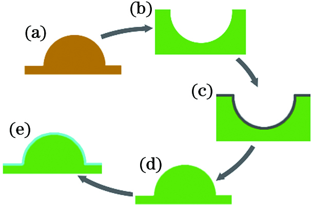
Fig. 1 shows the preparation flow diagram of the sticky, flexible PDMS hemisphere. First, a 3 mm diameter glass hemisphere is attached to the surface of a glass substrate. A PDMS prepolymer and its crosslink agent with a weight ratio of 10∶1 are evenly mixed by stirring; the mixture is poured onto the top surface of the glass hemisphere by a heat curing process. A concave PDMS hemisphere is obtained by directly detaching the glass hemisphere. Then, the concave PDMS hemisphere is modified using a surface plasma technique and subsequently immersed in ethanol for 4 h to facilitate the following separation. After drying with nitrogen, the concave PDMS hemisphere is transferred onto PDMS material to shape it to a convex PDMS hemisphere. Finally, the convex PDMS hemisphere is coated with the mixture of PDMS prepolymer and crosslink at a speed of 2000 r/min to obtain a sticky, flexible PDMS convex hemisphere.

Figure 1.Preparation flow diagram of flexible sticky macrosphere. (a) Glass convex hemisphere; (b) PDMS concave hemisphere; (c) surface modified PDMS concave hemisphere; (d)(e) PDMS convex hemisphere without mixture film of PDMS prepolymer and its crosslink agent
2.2 Rigid high-NA concave MLA preparation
Fig. 2 shows the preparation procedure of the rigid concave MLA master mold. First, a photoresist micropillar array structure is prepared on a chrome deposited fused glass, using a direct laser writing technique. The photoresist micropillar array structure is baked at 140 ℃ to melt the photoresist micropillar array. After cooling at room temperature, a convex MLA is prepared. Then, the mixture of PDMS prepolymer and its crosslink agent is poured onto the top surface of the photoresist MLA structure, followed by a heat curing process. A PDMS convex MLA structure is obtained by direct detachment from the photoresist MLA structure. Finally, epoxy resin prepolymer and its crosslink agent are mixed with a weight ratio of 4∶1 and subsequently poured onto the top surface of the PDMS convex MLA structure. After curing at 80 ℃ for 4 h, a rigid concave MLA master mold is obtained by directly detaching the PDMS convex MLA structure.
Figure 1.Preparation flow diagram of flexible sticky macrosphere. (a) Glass convex hemisphere; (b) PDMS concave hemisphere; (c) surface modified PDMS concave hemisphere; (d)(e) PDMS convex hemisphere without mixture film of PDMS prepolymer and its crosslink agent
2.3 Preparation of 3D ACE
When an elastic sphere is squeezed onto a rough surface,particles from the rough surface are facilely transferred onto the sphere’s surface upon external pressure removal. Based on this rationale, a simple, cost effective preparation method for 3D ACEs is proposed, as illustrated in Fig. 3. The mixture of PDMS prepolymer and its crosslink agent are spin-coated on the rigid concave MLA master mold at 2000 r/min for 1 min. After baking at 80 ℃ for 5 min, the PDMS is cured such that it can be shaped into a convex MLA film while it is sticky. The convex MLA PDMS film (hereafter the film) is subsequently squeezed using a flexible and sticky PDMS hemisphere (hereafter the hemisphere), and these are baked at 80 ℃ for 2 h to allow them to bond. The pressure force is abruptly removed, and the hemisphere, with the film attached, “bounces” as it recovers its shape, giving the film a spherical morphology.
Figure 3.Preparation flow diagram of a 3D ACE. (a) Rigid 2D concave MLA master mold; (b) PDMS film on the rigid 2D concave MLA master mold; (c) squeezing the PDMS dome for adhesion to the PDMS film; (d) schematic of a prepared 3D ACE
3 Results and discussion
Ommatidia are the units that constitute a compound eye. Therefore, they comprise a key component of a 3D ACE for clear, distortion-free imaging. Compared with other preparation methods of 2D planar ACEs[37-39], thermal reflow is a feasible method for preparing 2D planar close-packed high-NA ACEs with a high surface finish[40-41]. Fig. 4(a) shows the SEM image of the prepared micropillar array, where the diameter, height, and gap of micropillars are 18.8, 10.1, and 4.9 μm, respectively. Through thermal baking, the micropillar is melted into microdroplets. After cooling, the microdroplets recover to solid-phase microlenses, as shown in Fig. 4(b). The microlenses’ width and gap are measured as 20.3 and 3.5 μm, while the height remains almost constant. Furthermore, the NA of the microlens is expressed as follows[41]:
where H and D denote the height and diameter of the microlens, respectively, and n represents the material refractive index. NA denotes the maximum value when the ratio of the height and diameter is 0.5. This means that the microlens is a hemispherical morphology, indicating that the prepared 2D ACE has a high-NA.
| Structure | Diameter /μm | Height /μm | Gap /μm |
|---|
| MPA | 18.8 | 10.1 | 4.90 |
| 2D ACE | 20.3 | 10.1 | 3.50 |
| 3D ACE | 24.4 | 10.0 | 4.25 |
Table 1. Parameters of a micropillar array (MPA), 2D ACE, and 3D ACE
Figure 4.SEM images of 2D and 3D ACEs. (a)(b) SEM images of prepared micropillar and MLA; (c)--(e) SEM image and enlarged SEM images of a 3D ACE formed with a pressure force of 14 N
The geometric morphology of the microlens is closely related to the contact angle (CA) of molten photoresist microdroplets on the chrome plate. The molten micropillar is spread out over the chrome surface to form spherical or paraboloidal microdroplets[42]. The CA explains the spread of the microdroplets. The wider the liquid spreads, the smaller the CA and the larger the prepared microlens diameter. To analyze the thermodynamic equilibrium of photoresist microdroplets, the CA of a 2-μL deionized water droplet is measured to be 65.6° on chrome deposited fused silica at room temperature and 13.2° on naked fused silica. This directly demonstrates that the CA strongly depends on the material. This is because of the difference in surface tension of water on different material surfaces. Different liquids have different CAs on the same material surface. Temperature is an important factor affecting the CA. Therefore, the above analysis has shown that the prepared microlens has a higher NA on the chrome surface than the naked fused silica surface. In our experiment, according to structural parameters in Table 1, H/D of the prepared microlens is calculated as approximately 0.5, indicating that a high-NA planar 2D ACE is obtained.
Figs. 4(a)--(c) show SEM images of the 3D ACE prepared at a pressure force of 14 N. The eye displays a curved MLA, which is uniformly covered on the PDMS dome without any dust particles. The high surface cleanliness is due to the high-efficiency method that reduces the number of steps in the preparation process, thereby decreasing the possibility of contamination from dust particles. Fig. 4(c) shows a magnified SEM image of ommatidia formed on the curved surface. These ommatidia display a spherical morphology with a high surface finish. This means that the proposed preparation method can reproduce the surface finish of the 2D MLA master mold. LSCM indicates the width of the ommatidia, and the gap between them is 24.4 and 4.25 μm, respectively, as shown in Table 1. In contrast, the width and gap measurements of the microlenses in the prepared 2D planar convex ACE are 20.8 and 3.5 μm, respectively. As the film changes from a planar to a curved surface, its area increases, enlarging the ommatidia’s width and the gap between them. Despite the spherical shape of the bonding film, the cross-sectional widths of the ommatidia in the prepared 3D compound eye in the x and y directions remain equal.
To further demonstrate our method’s preparation efficacy, diameters, heights, and gaps of fifty ommatidia of the 3D ACE prepared at 14 N are measured from the center to the edge of the macroeye. Fig. 5 shows that the fifty ommatidia have highly consistent diameters, heights, and gaps. These results verify that the proposed method is highly effective for preparing 3D ACEs with good uniformity. SEM images of 3D ACEs formed at 2, 6, 14 N are shown in Fig. S2 (a)--(c), which are credible results. All three diagrams of the 3D ACEs show a highly uniform distribution of ommatidia on the macroeyes’ surfaces. These results prove once again that the proposed method can prepare 3D ACEs with high-quality. Moreover, Fig. S2 shows that prepared 3D ACEs at different press forces show a significant difference in width, indicating that the pressure force controls the geometric morphology of 3D ACE.
Figure 5.Diameter, height, and gap uniformity of ommatidia from center to the edge of the macroeye
To further demonstrate high level control over the geometric morphology of 3D ACE, the state of a 3-mm diameter flexible hemisphere under different pressures is theoretically analyzed, and the geometric morphologies of ACEs under different pressures are experimentally conducted. Fig. 6(a) shows the side views of 3D ACEs formed with increasing pressure forces (F=0, 6, 10, 14 N) for comparison. The hemisphere bonded with the film appears to be wearing a dome hat.
Figure 6.Hemisphere shape under squeezing and removal of squeezing. (a) Side view of a 3D ACE; (b) shape of the hemisphere as it is squeezed with different pressure forces; (c) height and width of the 3D ACE as a function of pressure force
This is because the bonding part of the film is torn down from the concave MLA master mold as the pressure force is abruptly removed. The diagrams show that the hemisphere height decreased after the film was bonded with the hemisphere’s top. The dynamic process of squeezing the hemisphere is simulated using the finite element method, as shown in Fig. 6(b). As the pressure force and bonding zone area increase, the hemisphere’s surface increasingly flattens. As the pressure force is removed, the bonding film is transferred onto the top of the hemisphere. The recovery of the hemisphere must overcome the resistance of the film, and the restoring force of the hemisphere causes the film to swell. The hemisphere’s part is not directly attached to the bonding film returns to its original shape without any deformation. The larger the film’s bonding area, the greater the resistance, and hence, the lower the hemisphere’s height. When the hemisphere is completely contracted into the PDMS substrate, the film bonds with the substrate and the bonding zone area reaches a maximum. Consequently, the hemisphere has its lowest height after recovery. On the other hand, as the pressure force increases, the restoring force of the squashed hemisphere becomes larger, thus improving the film’s swollen height.
Fig. 6(c) shows the morphologies (i.e., width and height) of 3D ACEs, prepared with pressures varying from 2 to 14 N, in a step of 2 N. Both the height and width increase with the pressure force and remain almost constant at F>14 N. This indicates optimized dimensions of 3D ACEs at 14 N. These results confirm that the proposed method can prepare 3D ACEs with controllable geometric morphology. Generally, the externally driven deformation method has two indispensable processes: manual detachment of a 2D planar ACE film from the master mold and deformation into 3D ACE. Obviously, in this preparation process of 3D ACEs, both detachment and deformation processes are completely spontaneous without any manual operation. As a comparison, the operational steps of preparing 3D ACEs using the externally driven deformation method are summarized, as shown in Table S1 of Supporting Information. Our preparation method effectively reduces the number of procedural preparation steps, thereby improving the preparation efficiency. Importantly, the proposed method can prepare multiple 3D ACEs simultaneously. Notably, the laboratory requirement for preparing multiple 3D ACEs is minimal. Notably, if the PDMS material is replaced with flexible UV resin, the proposed method can be used in the roll-to-roll fabrication for mass production. Therefore, the proposed preparation method is simple and highly efficient, and it opens up the possibility of mass production of 3D ACEs for a wide range of applications.
A significant feature of a 3D ACE is a wide FOV, which is closely related to the width and height of the compound eye. A theoretical value for the FOV can be expressed as
where η is the height-to-width ratio of the 3D ACE. Fig. S3 shows that the height-to-width ratio of the compound eye is increased with the pressure force F=14 N, and after that, it remains constant. According to the above equation, the FOV increases as the height-to-width ratio ranges from 0 to 0.5. Therefore, we conclude that the 3D ACE has a maximum theoretical FOV value of 145.7° at F=14 N, allowing wide optical imaging.
Optical imaging of the prepared 3D ACE is a key factor for determining the efficacy of the proposed preparation method. An optical microscope (Olympus, BX53M) with a 20× objective lens is used, as shown in Fig. S4. A black plastic sheet with a transparent letter “A” is placed on the white light LED source of the optical microscope. Images formed by different regions of the compound eye are visible using the charge-coupled device camera. Images formed at the edges of the photographs are indistinct and even distorted [Fig. 7(a)]. This is due to the nonplanar distribution of microlenses; rapid-focus images can only be located on a small region of the spherical surface. As the compound eye moves up, the core zone in the camera of the charge-coupled device becomes obscured, and a wider field of clear “A” images forms, as shown in Fig. 7(b)--(d). Also, Fig. S5(a)--(d) show that sharp focal points are visible by adjusting the objective lens from far to near. These clear images and sharp focal points demonstrate the PDMS hemisphere microlenses have high uniformity and excellent morphology. Therefore, the proposed high-efficiency preparation method has a marginal impact on the morphology of microlenses even though the convex MLA film becomes deformed during the preparation process.
Figure 7.Imaging properties of the 3D ACE. (a) Clear “A” images from the top of the 3D ACE; (b) clear “A” images from the outer part (in the annulus) of the 3D ACE; (c)(d) larger-magnification “A” images of the lower left and right zones in Fig.7(b)
In addition to the optical imaging formed with normal incidence,the oblique incidence was also investigated. A measurement system equipped with an objective lens (20×), a laser source (λ=632.8 nm), and a charge-coupled device camera were set up, as shown in Fig. S6. Notably, this setup has a slight difference in the light source from that in Fig. S4. The light source is mounted on a shaft to adjust the incident light direction in the range of -90°-90°. The incident angle of the laser irradiating the compound eye is adjustable. Fig. 8(a)--(c) show the sharp focal spots from the charge-coupled device camera formed at incident angles of 0°, 30°, 60°, respectively. To further examine the image quality of the focal spots, the cross-sectional intensity distribution of a single focal spot along the x and y axes was investigated, as shown in Fig. 8(d)--(f), the FWHM is full width at half maximum. The focal spots maintain good consistency at incident angles of 0°, 30°, 60°. These results confirm that the prepared compound eye has a FOV of 120° without image deformation. However, we find that the experimental value of the FOV (≈140.2°) is less than the theoretical value (≈145.4°). The difference might be due to the inherent planar photodetector.
Figure 8.Characterization of the wide FOV of the 3D ACE. (a)--(c) Optical images of focal spots formed by the 3D ACE, inset is an image of a single focal spot; (d) intensity distribution along the x and y axes at an incident angle of 0°; (e) intensity distribution along the x axis at different incident angles; (f) intensity distribution along the y axis at different incident angles
4 Conclusion
Our study has shown that a simple,efficient, and flexible method can be developed to prepare 3D ACEs using a sticky PDMS dome to squeeze a PDMS film on a concave MLA master mold by removing the pressure force. The proposed preparation method can effectively adjust the morphology of 3D ACEs by controlling the pressure force. The characterization results consistently show that the 3D ACEs formed with this preparation method have a high number of uniformly distributed ommatidia with a high-quality finish. Our investigations using optical imaging demonstrate that the proposed preparation method can allow for high optical performance, distortion-free imaging, and a wide FOV (up to 140.2°). Furthermore, the proposed method is highly efficient, and it has significant potential for the mass production of 3D ACEs.
Acknowledgments
This study was supported by the National Science Foundation of China (NSFC) (61805179, 61905180) and the Science Foundation of Zhejiang (LY19F050013).
Declaration of competing interest
The authors declare that there are no conflicts of interest related to this article.
References
[1] Stollberg K, Brückner A, Duparré J et al. The Gabor superlens as an alternative wafer-level camera approach inspired by superposition compound eyes of nocturnal insects[J]. Optics Express, 17, 15747-15759(2009). http://www.opticsinfobase.org/oe/abstract.cfm?uri=oe-17-18-15747
[2] Jeong K H. Biologically inspired artificial compound eyes[J]. Science, 312, 557-561(2006). http://search.ebscohost.com/login.aspx?direct=true&db=aph&AN=20788641&site=ehost-live
[3] Floreano D, Pericet-Camara R, Viollet S et al. Miniature curved artificial compound eyes[J]. Proceedings of the National Academy of Sciences, 110, 9267-9272(2013). http://search.ebscohost.com/login.aspx?direct=true&db=aph&AN=88092641&site=ehost-live
[4] Yoshimoto K, Yamada K, Sasaki N et al. Evaluation of a compound eye type tactile endoscope[J]. Endoscopic Microscopy VIII, 8575, 85750Z(2013). http://proceedings.spiedigitallibrary.org/proceeding.aspx?articleid=1668072
[5] Ko H C, Stoykovich M P, Song J Z et al. A hemispherical electronic eye camera based on compressible silicon optoelectronics[J]. Nature, 454, 748-753(2008). http://www.ingentaconnect.com/content/np/00280836/2008/00000454/00007205/art00027
[6] Prabhakara R S, Wright C H G, Barrett S F. Motion detection: a biomimetic vision sensor versus a CCD camera sensor[J]. IEEE Sensors Journal, 12, 298-307(2012).
[7] Song Y M, Xie Y Z, Malyarchuk V et al. Digital cameras with designs inspired by the arthropod eye[J]. Nature, 497, 95-99(2013).
[8] Ma Z C, Hu X Y, Zhang Y L et al. Smart compound eyes enable tunable imaging[J]. Advanced Functional Materials, 29, 1903340(2019). http://onlinelibrary.wiley.com/doi/10.1002/adfm.201903340
[9] Wu D, Wang J N, Niu L G et al. Bioinspired fabrication of high-quality 3D artificial compound eyes by voxel-modulation femtosecond laser writing for distortion-free wide-field-of-view imaging[J]. Advanced Optical Materials, 2, 751-758(2014). http://onlinelibrary.wiley.com/doi/10.1002/adom.201400175/abstract
[10] Li J, Wang W J, Mei X S et al. The formation of convex microstructures by laser irradiation of dual-layer polymethylmethacrylate (PMMA)[J]. Optics & Laser Technology, 106, 461-468(2018). http://www.sciencedirect.com/science/article/pii/S0030399217316031
[11] Shao J Y, Ding Y C, Zhai H P et al. Fabrication of large curvature microlens array using confined laser swelling method[J]. Optics Letters, 38, 3044-3046(2013). http://www.opticsinfobase.org/ol/abstract.cfm?uri=ol-38-16-3044
[12] Sun Y L, Dong W F, Niu L G et al. Protein-based soft micro-optics fabricated by femtosecond laser direct writing[J]. Light: Science & Applications, 3, e129(2014). http://www.nature.com/articles/lsa201410
[13] Wu D, Wu S Z, Niu L G et al. High numerical aperture microlens arrays of close packing[J]. Applied Physics Letters, 97, 031109(2010). http://ieeexplore.ieee.org/xpl/articleDetails.jsp?arnumber=5520003
[14] Xia H, Zhang W Y, Wang F F et al. Three-dimensional micronanofabrication via two-photon-excited photoisomerization[J]. Applied Physics Letters, 95, 083118(2009). http://ieeexplore.ieee.org/xpls/abs_all.jsp?arnumber=5230450
[15] Chen F, Liu H W, Yang Q et al. Maskless fabrication of concave microlens arrays on silica glasses by a femtosecond-laser-enhanced local wet etching method[J]. Optics Express, 18, 20334(2010).
[16] Fang C L, Zheng J, Zhang Y J et al. Antireflective paraboloidal microlens film for boosting power conversion efficiency of solar cells[J]. ACS Applied Materials & Interfaces, 10, 21950-21956(2018).
[17] Shao J Y, Ding Y C, Wang W J et al. Generation of fully-covering hierarchical micro-/nano-structures by nanoimprinting and modified laser swelling[J]. Small, 10, 2595-2601(2014). http://europepmc.org/abstract/med/24616236
[18] Wu F F, Shi G, Xu H B et al. Fabrication of antireflective compound eyes by imprinting[J]. ACS Applied Materials & Interfaces, 5, 12799-12803(2013). http://www.ncbi.nlm.nih.gov/pubmed/24294975
[19] Gao X, Yan X, Yao X et al. The dry-style antifogging properties of mosquito compound eyes and artificial analogues prepared by soft lithography[J]. Advanced Materials, 19, 2213-2217(2007).
[20] Ko D H, Tumbleston J R, Henderson K J et al. Biomimetic microlens array with antireflective “moth-eye” surface[J]. Soft Matter, 7, 6404-6407(2011). http://www.tandfonline.com/servlet/linkout?suffix=cit0013&dbid=16&doi=10.1080%2F05704928.2017.1324469&key=10.1039%2Fc1sm05302g
[21] Hung S Y. Optimal design using thermal reflow and caulking for fabrication of gapless microlens array mold inserts[J]. Optical Engineering, 46, 043402(2007). http://spie.org/x648.html?product_id=746153
[22] Wang M J, Wang T S, Shen H H et al. Subtle control on hierarchic reflow for the simple and massive fabrication of biomimetic compound eye arrays in polymers for imaging at a large field of view[J]. Journal of Materials Chemistry C, 4, 108-112(2016). http://d.wanfangdata.com.cn/periodical/f86b64386067bc4693798e97e5e6821d
[23] Wang T, Yu W, Li C et al. Biomimetic compound eye with a high numerical aperture and anti-reflective nanostructures on curved surfaces[J]. Optics Letters, 37, 2397-2399(2012).
[24] Serra F, Gharbi M A, Luo Y M et al. Curvature-driven, one-step assembly of reconfigurable smectic liquid crystal “compound eye” lenses[J]. Advanced Optical Materials, 3, 1287-1292(2015). http://onlinelibrary.wiley.com/doi/10.1002/adom.201500153
[25] Zhang D W, Xu Q, Fang C L et al. Fabrication of a microlens array with controlled curvature by thermally curving photosensitive gel film beneath microholes[J]. ACS Applied Materials & Interfaces, 9, 16604-16609(2017). http://pubs.acs.org/doi/10.1021/acsami.7b00766
[26] Jiang C B, Li X M, Tian H M et al. Lateral flow through a parallel gap driven by surface hydrophilicity and liquid edge pinning for creating microlens array[J]. ACS Applied Materials & Interfaces, 6, 18450-18456(2014). http://europepmc.org/abstract/med/25348103
[27] Li X M, Ding Y C, Shao J Y et al. Fabrication of microlens arrays with well-controlled curvature by liquid trapping and electrohydrodynamic deformation in microholes[J]. Advanced Materials, 24, OP165-OP169(2012).
[28] Li X M, Tian H M, Ding Y C et al. Electrically templated dewetting of a UV-curable prepolymer film for the fabrication of a concave microlens array with well-defined curvature[J]. ACS Applied Materials & Interfaces, 5, 9975-9982(2013). http://europepmc.org/abstract/med/23902897
[29] Bian H, Wei Y, Yang Q et al. Direct fabrication of compound-eye microlens array on curved surfaces by a facile femtosecond laser enhanced wet etching process[J]. Applied Physics Letters, 109, 221109(2016). http://scitation.aip.org/content/aip/journal/apl/109/22/10.1063/1.4971334
[30] Liu H W, Chen F, Yang Q et al. Fabrication of bioinspired omnidirectional and gapless microlens array for wide field-of-view detections[J]. Applied Physics Letters, 100, 133701(2012). http://scitation.aip.org/content/aip/journal/apl/100/13/10.1063/1.3696019
[31] Liang Y, Zhu T F, Xi M J et al. Fabrication of biomimetic compound eye on single crystal diamond[J]. Optics Express, 27, 20508-20515(2019). http://www.ncbi.nlm.nih.gov/pubmed/31510143
[32] Deng Z F, Chen F, Yang Q et al. Compound eyes: dragonfly-eye-inspired artificial compound eyes with sophisticated imaging[J]. Advanced Functional Materials, 26, 1853(2016).
[33] Li J, Wang W J, Mei X S et al. Fabrication of artificial compound eye with controllable field of view and improved imaging[J]. ACS Applied Materials & Interfaces, 12, 8870-8878(2020). http://www.researchgate.net/publication/339006397_Fabrication_of_Artificial_Compound_Eye_with_Controllable_Field_of_View_and_Improved_Imaging
[34] Qu P B, Chen F, Liu H W et al. A simple route to fabricate artificial compound eye structures[J]. Optics Express, 20, 5775-5782(2012).
[35] Kuo W K, Kuo G F, Lin S Y et al. Fabrication and characterization of artificial miniaturized insect compound eyes for imaging[J]. Bioinspiration & Biomimetics, 10, 056010(2015). http://www.ncbi.nlm.nih.gov/pubmed/26414303
[36] Cao J J, Hou Z S, Tian Z N et al. Bioinspired zoom compound eyes enable variable-focus imaging[J]. ACS Applied Materials & Interfaces, 12, 10107-10117(2020).
[37] Chang C Y, Yang S Y, Huang L S et al. Fabrication of plastic microlens array using gas-assisted micro-hot-embossing with a silicon mold[J]. Infrared Physics & Technology, 48, 163-173(2006). http://www.sciencedirect.com/science/article/pii/S1350449505001222
[38] Kim J Y, Brauer N B, Fakhfouri V et al. Hybrid polymer microlens arrays with high numerical apertures fabricated using simple ink-jet printing technique[J]. Optical Materials Express, 1, 259-269(2011). http://www.tandfonline.com/servlet/linkout?suffix=CIT0007&dbid=16&doi=10.1080%2F01694243.2018.1461447&key=10.1364%2FOME.1.000259
[39] Yang Y D, Huang X P, Zhang X Y et al. Supercritical fluid-driven polymer phase separation for microlens with tunable dimension and curvature[J]. ACS Applied Materials & Interfaces, 8, 8849-8858(2016). http://europepmc.org/abstract/MED/26999714
[40] Yang H, Chao C K, Wei M K et al. High fill-factor microlens array mold insert fabrication using a thermal reflow process[J]. Journal of Micromechanics and Microengineering, 14, 1197-1204(2004). http://adsabs.harvard.edu/abs/2004JMiMi..14.1197Y
[41] Jung H, Jeong K H. Monolithic polymer microlens arrays with high numerical aperture and high packing density[J]. ACS Applied Materials & Interfaces, 7, 2160-2165(2015). http://www.ncbi.nlm.nih.gov/pubmed/25612820
[42] Chen C T, Tseng Z F, Chiu C L et al. Self-aligned hemispherical formation of microlenses from colloidal droplets on heterogeneous surfaces[J]. Journal of Micromechanics and Microengineering, 19, 025002(2009). http://adsabs.harvard.edu/cgi-bin/nph-data_query?bibcode=2009JMiMi..19b5002C&db_key=PHY&link_type=EJOURNAL