
Yang Yongqiang, Chen Jie, Song Changhui, Wang Di, Bai Yuchao. Current Status and Progress on Technology of Selective Laser Melting of Metal Parts[J]. Laser & Optoelectronics Progress, 2018, 55(1): 11401
- Laser & Optoelectronics Progress
- Vol. 55, Issue 1, 11401 (2018)
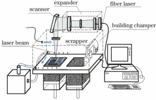
Fig. 1. Principle diagram of SLM processing
![SEM images of 316L-NiB alloys formed by SLM process (f=20 Hz; N=20). (a) τ=2 ms, Ep=3.47 J; (b)(c) τ=2 ms, Ep=2.45 J; (d) τ=4 ms, Ep=4.06 J[22]](/richHtml/lop/2018/55/1/011401/img_2.jpg)
Fig. 2. SEM images of 316L-NiB alloys formed by SLM process (f=20 Hz; N=20). (a) τ=2 ms, Ep=3.47 J; (b)(c) τ=2 ms, Ep=2.45 J; (d) τ=4 ms, Ep=4.06 J[22]
Fig. 3. Surface profiles of 316L-NiB samples formed by SLM process. (a) f=20 Hz, Ep=3.86 J, τ=3 ms; (b) f=40 Hz, Ep=1.58 J, τ=2 ms[22]
Fig. 4. Macrograph of formed porous material[23]
Fig. 5. Grain structures under SEM[23]
Fig. 6. Inclination angle γ between SLM specimen and substrate[28]
Fig. 7. Fracture morphologies after tensile tests at room temperature. (a)-(c) Cast; (d)-(f) samples formed by SLM with inclination angle of 90°; (g)-(i) samples after heat-treatment at 723 K[28]
Fig. 8. Knee implants with porous solid structures deposited on dissimilar-material substrate[31]
Fig. 9. Cu-4.3%Sn etched by Klemm's I reagent under optical microscope[36]
Fig. 10. Stress-strain curves for Cu-10Sn bronze formed by SLM and cast at room temperature, where inset is Cu-10Sn bronze propeller fabricated by SLM[38]
Fig. 11. (a) SLM process; (b) different orientations of cylinder on substrate as shown in Fig. 11 (a); (c) geometric parameters of specimens for tensile tests[41]
Fig. 12. Aviation rotating shaft component[44]
Fig. 13. Complex aviation components formed by SLM[45]
Fig. 14. Surgical spine guide-plate formed by SLM[46]
Fig. 15. Knee joint implant formed by SLM[47]
Fig. 16. SEM images of Co-Cr-alloy cardiovascular stents formed by SLM. (a)(b) Ppeak=180 W, t=100 μs; (c)(d) Ppeak=40 W, t=120 μs[48]
Fig. 17. (a) Ti-6Al-4V powder; (b) CAD model; (c) SLM process; (d) manufactured model[49]
Fig. 18. (a) CAD design model; (b) alloy implant formed by SLM and substrate components; (c) implant specimen after polishing[50]
Fig. 19. Porous implants used in living animal experiments and arrows indicate building orientation. (a) P300 plate; (b) P600 plate; (c) P900 plate; (d) P300 cylinder; (e) P600 cylinder; (f) P900 cylinder[51]
Fig. 20. Specimens formed by SLM[52]
Fig. 21. Die casting mold formed by SLM[53]
Fig. 22. CAD-models of optimized bionic structure and its support structure[55]
Fig. 23. Free-assembly universal joint formed by SLM[57]
Fig. 24. Diagram of SLM process with high-speed camera monitor[61]
| ||||||||||||||||||||||||||||||||||||||||||||||||||||||||||||||||||||||||||||||||||||||||||||||||||||||||||||||||||||||||||||||||
Table 1. Ra, Rq and Rz of specimens before and after surface treatment[29]

Set citation alerts for the article
Please enter your email address
© Copyright 2018-2021 | Chinese Laser Press. All Rights Reserved 沪ICP备15018463号-20