
Xiaogang Zhu, Anping Dong, Lingyu Cheng, Jing Sun, Zhengwu Liu, Lijie Guo. Study on AlSi10Mg Alloy with Complex Flow Channels by Laser Powder Bed Fusion[J]. Laser & Optoelectronics Progress, 2023, 60(7): 0714006
- Laser & Optoelectronics Progress
- Vol. 60, Issue 7, 0714006 (2023)
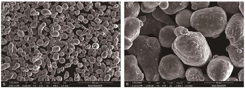
Fig. 1. SEM images of AlSi10Mg alloy powder. (a) 400×; (b) 2000×
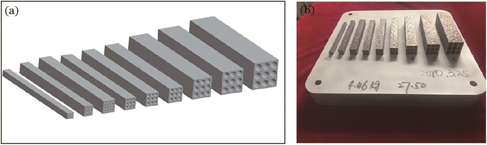
Fig. 2. Circular channel samples of different diameters. (a) Three-dimensional model of specimens; (b) circular channel formed by LPBF
Fig. 3. Ridge shape channel samples with different section sizes.(a) Three-dimensional model of specimens; (b) schematic of section size dimensions when B=6 mm; (c) ridge shape channel formed by LPBF
Fig. 4. Schematic of test size of channel sample. (a) Circular channel; (b) ridge shape channel
Fig. 5. Three-dimensional model of complex channel cooling element.(a) Front view of model; (b) bottom view of model; (c) position of ridge shape channel; (d) partial section view of side channel
Fig. 6. Schematic of inclination angle. (a) Circular channel; (b) ridge shape channel
Fig. 7. Schematic of mechanism of powder particles adhering to inner surface of channel. (a) Circular channel; (b) ridge shape channel
Fig. 8. Circular channel samples formed by LPBF with different diameters. (a) Front view and (b) top view of specimens; (c) circular channel sample formed by LPBF with axial section of channel; (d) circular channel sample formed by LPBF; (e) Φ2 mm, (f) Φ2.5 mm, (g) Φ3 mm, (h) Φ4 mm, (i) Φ5 mm, and (j) Φ6 mm of inner surface of channel
Fig. 9. Ridge shape channel samples formed by LPBF with different section sizes. (a) Front view and (b) top view of specimens; (c) ridge shape channel samples formed by LPBF with axial section of channel; (d) ridge shape channel samples formed by LPBF; (e) B=2 mm, (f) B=2.5 mm, (g) B=3 mm, (h) B=4 mm, (i) B=5 mm, and (j) B=6 mm of inner surface of channel
Fig. 10. Powder cleaning scheme for complex channel cooling element formed by LPBF at the turning part of flow channel. (a) Process hole for powder discharge with a diameter of 2 mm; (b) process hole is blocked by set screw and thread glue
Fig. 11. Complex channel cooling element formed by LPBF.(a)LPBF forming process of channel 1;(b)LPBF forming process of channel 2; (c) top view; (d) bottom image; (e) side view; (f) partial section view
Fig. 12. X-ray test of complex channel cooling element. (a) Location diagram; detection images of (b) 1# area, (c) 2# area, (d) 3# area, (e) 4# area, and (f) 5# area
Fig. 13. CT test of channel cooling element formed by LPBF
Fig. 14. Pressure test of complex channel cooling element. (a) Filling channels with water; (b) pressure gauge; (c) process of pressure test
|
Table 1. Chemical composition of AlSi10Mg alloy powder
| ||||||||||||||||||||||||||||||||||||||||||||||||||||
Table 2. Measured diameter of circular channel size
| ||||||||||||||||||||||||||||||||||||||||||||||||||||
Table 3. Measured diameter of ridge shape channel size

Set citation alerts for the article
Please enter your email address
© Copyright 2018-2021 | Chinese Laser Press. All Rights Reserved 沪ICP备15018463号-20