• Laser & Optoelectronics Progress
  • Vol. 59, Issue 9, 0922012 (2022)
Yisha Cao1、2, Feng Tang1、2、*, Xiangzhao Wang1、2, Yang Liu1、2, Peng Feng1, Yunjun Lu1、2, and Fudong Guo1
Author Affiliations
  • 1Laboratory of Information Optics and Optoelectronic Technology, Shanghai Institute of Optics and Fine Mechanics, Chinese Academy of Sciences, Shanghai 201800, China
  • 2Center of Materials Science and Optoelectronics Engineering, University of Chinese Academy of Sciences, Beijing 100049, China
  • show less
    DOI: 10.3788/LOP202259.0922012 Cite this Article Set citation alerts
    Yisha Cao, Feng Tang, Xiangzhao Wang, Yang Liu, Peng Feng, Yunjun Lu, Fudong Guo. Measurement Techniques for Distortion of Lithography Projection Objective[J]. Laser & Optoelectronics Progress, 2022, 59(9): 0922012 Copy Citation Text show less
    Formation principle of the distortion[22]
    Fig. 1. Formation principle of the distortion[22]
    Distortion of the optical system. (a) Radial symmetry distortion (k1=-0.5); (b) decentering distortion(p1=p2=0.5)
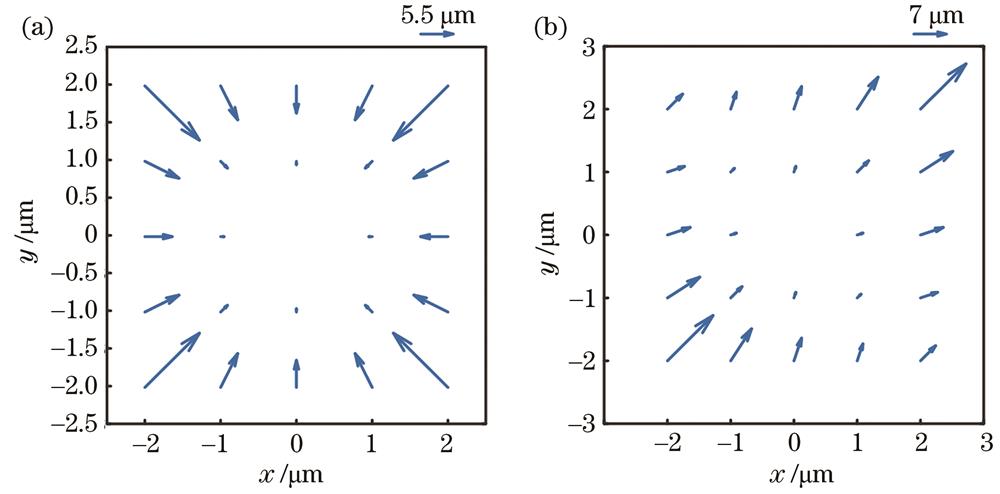
    Fig. 2. Distortion of the optical system. (a) Radial symmetry distortion (k1=-0.5); (b) decentering distortion(p1=p2=0.5)
    Imaging results of the optical system. (a) Imaging result of an optical system without distortion; (b) imaging result of an optical system with positive distortion (k1=0.5); (c) imaging result of an optical system with negative distortion (k1=-0.5)
    Fig. 3. Imaging results of the optical system. (a) Imaging result of an optical system without distortion; (b) imaging result of an optical system with positive distortion (k1=0.5); (c) imaging result of an optical system with negative distortion (k1=-0.5)
    Radial distortion component and tangential distortion component in decentering distortion
    Fig. 4. Radial distortion component and tangential distortion component in decentering distortion
    Schematic diagram of actual imaging position and ideal imaging position
    Fig. 5. Schematic diagram of actual imaging position and ideal imaging position
    Distortion detection principle of the lithography projection objective
    Fig. 6. Distortion detection principle of the lithography projection objective
    Diagram of the distortion measurement device of lithography projection objective
    Fig. 7. Diagram of the distortion measurement device of lithography projection objective
    Flow chart of distortion measurement based on exposure
    Fig. 8. Flow chart of distortion measurement based on exposure
    Inter-field error and intra-field error[36,41]
    Fig. 9. Inter-field error and intra-field error[36,41]
    Box measurement mark[2]
    Fig. 10. Box measurement mark[2]
    Shear exposure field. (a) X shear exposure field; (b) Y shear exposure field[2]
    Fig. 11. Shear exposure field. (a) X shear exposure field; (b) Y shear exposure field[2]
    Schematic diagram of exposure distortion measurement of the SMEE[3]
    Fig. 12. Schematic diagram of exposure distortion measurement of the SMEE[3]
    Schematic diagram of aerial image position measurement based on slit scanning method[4]
    Fig. 13. Schematic diagram of aerial image position measurement based on slit scanning method[4]
    Distortion detection based on aerial image[6]
    Fig. 14. Distortion detection based on aerial image[6]
    Principle of the differential measurement[14]
    Fig. 15. Principle of the differential measurement[14]
    Principle of the Shaker-Hartmann sensor. (a) Ideal wavefront; (b) deformed wavefront[11]
    Fig. 16. Principle of the Shaker-Hartmann sensor. (a) Ideal wavefront; (b) deformed wavefront[11]
    Principle of measuring the position deviation of the marked image point with the Shake-Hartmann sensor. (a) Horizontal; (b) vertical[15]
    Fig. 17. Principle of measuring the position deviation of the marked image point with the Shake-Hartmann sensor. (a) Horizontal; (b) vertical[15]
    Principle of the SMEE interferometer[45]
    Fig. 18. Principle of the SMEE interferometer[45]
    Optical path diagram of the point diffraction interferometer for measuring distortion[16]
    Fig. 19. Optical path diagram of the point diffraction interferometer for measuring distortion[16]
    Wave aberration detection system of projection objective based on Ronchi shearing interference[51]
    Fig. 20. Wave aberration detection system of projection objective based on Ronchi shearing interference[51]
    Schematic diagram of the measurement grid[19]
    Fig. 21. Schematic diagram of the measurement grid[19]
    Reticle alignment marks (2×7) on both ends of the mask are used to align the reticle[52]
    Fig. 22. Reticle alignment marks (2×7) on both ends of the mask are used to align the reticle[52]
    Principle of measuring distortion of the projection objective of the lithography machine based on Moiré fringe[53]
    Fig. 23. Principle of measuring distortion of the projection objective of the lithography machine based on Moiré fringe[53]
    Lithography modelδyz'
    ASML PAS 5500/100D60
    ASML PAS 5500/450F20
    ASML TWINSCAN XT∶860M10
    ASML TWINSCAN XT∶1250B8
    ASML TWINSCAN NXT∶1950i0.6
    ASML NXE∶ 31001.5
    ASML NXE∶ 3400B0.4
    Table 1. Absolute distortion of the projection objective of different lithography machines
    Distortion measurement technologyMeasurement accuracyMeasurement speedMain source of errorWays to improve
    Exposure methodmediumlow

    1)stage positioning error;

    2)overlay measurement error

    1)eliminate the influence of stage positioning error through algorithm;

    2)improve the accuracy of the overlay measuring instrument

    Aerial image measurement methodhighhighstage positioning errorimprove measurement accuracy through methods such as differential measurement
    Wavefront measurement methodhighmediumstage positioning errormulti-channel measurement technology
    Table 2. Comparison results of three distortion detection technologies
    Yisha Cao, Feng Tang, Xiangzhao Wang, Yang Liu, Peng Feng, Yunjun Lu, Fudong Guo. Measurement Techniques for Distortion of Lithography Projection Objective[J]. Laser & Optoelectronics Progress, 2022, 59(9): 0922012
    Download Citation