1Ministry of Industry and Information Technology Key Laboratory of Micro-Nano Optoelectronic Information System, School of Science, Harbin Institute of Technology, Shenzhen 518055, China
2Guangdong Provincial Key Laboratory of Semiconductor Optoelectronic Materials and Intelligent Photonic Systems, Shenzhen 518055, China
3Department of Electrical and Computer Engineering & Institute for Research in Electronics and Applied Physics (IREAP), University of Maryland, College Park, Maryland 20742, USA
Backward stimulated Brillouin scattering (SBS) is widely exploited for various applications in optics and optoelectronics. It typically features a narrow gain bandwidth of a few tens of megahertz in fluoride crystals. Here we report a hundredfold increase of SBS bandwidth in whispering-gallery mode resonators. The crystalline orientation results in a large variation of the acoustic phase velocity upon propagation along the periphery, from which a broad Brillouin gain is formed. Over 2.5 GHz wide Brillouin gain profile is theoretically found and experimentally validated. SBS phenomena with Brillouin shift frequencies ranging from 11.73 to 14.47 GHz in ultrahigh QZ-cut magnesium fluoride cavities pumped at the telecommunication wavelength are demonstrated. Furthermore, the Brillouin–Kerr comb in this device is demonstrated. Over 400 comb lines spanning across a spectral window of 120 nm are observed. Our finding paves a new way for tailoring and harnessing the Brillouin gain in crystals.
1. INTRODUCTION
Backward stimulated Brillouin scattering (SBS), as an inelastic scattering effect governed by third-order nonlinearities, has been extensively investigated since its discovery [1]. To harness backward SBS, optical waveguides and resonators have been great platforms to enhance the interaction between photons and phonons [2–4]. In optical fibers, backward SBS has been applied in various areas including slow light [5], pulse manipulation [6], and light storage [7]. Nanostructured photonic crystal fibers and micro/nano-size fibers are also utilized [8,9]. Recently, on-chip integrated waveguides have been widely studied for SBS [3]. Hybrid integration of high gain material onto a silicon chip is reported [10]. Giant Brillouin gain in nanoscale silicon waveguides is also studied [11]. Recently, enhanced Brillouin gain was also found in multilayer silicon nitride waveguides with acoustic guidance [12].
On the other hand, optical cavities with high quality (Q) factor further reduce the continuous-wave (CW) threshold power of SBS. Among various resonators, whispering-gallery mode (WGM) [13] and on-chip racetrack waveguide have been popular platforms in exploiting nonlinear photonic applications [4]. WGM cavities have been extensively investigated for a variety of light–matter interactions. For instance, free electrons can be coupled and controlled with WGMs [14]. Kerr frequency combs and Raman lasing are also demonstrated with WGM cavities [15,16]. Optomechanics with WGMs have also received widespread attention [17–19].
Backward SBS in WGM cavities was first demonstrated in fused silica and calcium fluoride host materials [20,21]. To date, versatile applications using SBS in WGM cavities have been developed including narrow-linewidth Brillouin lasers [22], low-noise microwave synthesizers [23], and Brillouin gyroscopes [24–26]. Resonant SBS can also be explored in photonic integrated circuit using popular host materials [25,27]. The sub-hertz fundamental linewidth resonant Brillouin laser has been recently demonstrated [25].
Sign up for Photonics Research TOC. Get the latest issue of Photonics Research delivered right to you!Sign up now
It is well known that the orientation of crystalline axes plays an important role in bulk nonlinear optics [28]. It is also interesting to explore it within WGM cavities. For instance, in X-cut WGM cavities made from beta barium borate (BBO), TM polarized optical WGMs experience oscillatory refractive indices along the circumference. This leads to a wide-range cyclic phase matching for second-harmonic generation [29]. In a similar manner, the crystalline orientation can also affect the phase velocity of the acoustic wave upon propagation in the periphery [20,30]. However, it is usually treated as a drawback, and the Brillouin gain profile in such a WGM configuration has not been well investigated.
Here, we reveal both theoretically and experimentally that the oscillatory acoustic phase velocity along the light path of WGMs results in a broadened Brillouin gain. We characterize, for the first time, the observation of backward SBS in Z-cut magnesium fluoride WGM cavities. CW threshold power of 3.4 mW is measured. In contrast to regular gain bandwidth of a few tens of megahertz in fluoride crystals, over 2.5 GHz range broad Brillouin gain in a single crystalline cavity is revealed by wide-range backward SBS. The hundredfold increase of gain bandwidth can facilitate the generation of Stokes and, thus, further application of SBS pumped Kerr combs. For instance, we further demonstrate the generation of Brillouin–Kerr frequency combs in such resonators. We obtain over 400 comb lines in the telecommunication window.
2. RESULTS
A. Broadened Brillouin Gain Principle
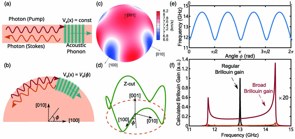
Figure 1(a) shows the schematic of the regular SBS process. The pump light beam is backscattered into the Stokes beam by a forward traveling longitudinal acoustic wave. As a result, the electrostriction effect from the interference between the pump and Stokes beams strengthens the acoustic density wave. From the viewpoint of the conservation of momentum and energy in the interaction between photons and phonons, the Brillouin shift frequency can be determined by , with being the pump wavelength in vacuum, the effective refractive index, and being the phase velocity of the acoustic wave. In crystalline materials, the acoustic phase velocity relies on the orientation of crystal axes. In the straight path case, can be seen as a constant value, while in a curve path inside a crystal, depends on its relative position to the crystal axes. Figure 1(b) shows the case of a curve path in a Z-cut crystalline plane with an angle-dependent acoustic velocity .
Figure 1.(a) Illustration of the regular backward SBS in a straight path, where the phase velocity of the acoustic wave is a constant. (b) Illustration of the backward SBS process along a curve path, where is dependent on the orientation of the crystal. (c) Calculated of the longitudinal acoustic wave of projected in 3D onto the unit sphere by solving the Christoffel equation. (d) Illustration of the oscillatory as the acoustic wave is traveling along the circumference of a Z-cut disk. (e) Calculated Brillouin shift frequency as a function of the angle for one round trip corresponding to a path length of . (f) Calculated Brillouin gain profiles in assuming a regular gain bandwidth of 20 MHz along a straight path (black). Over 2.5 GHz broadened Brillouin gain profile (orange) is found for one round trip of the Z-cut disk resonator. The upper curve is the broad gain curve magnified by a factor of 20 for clarity.
It is well known that the phase velocity of acoustic waves in a solid can be theoretically predicted from the stiffness tensor by solving the Christoffel equation [31]. Figure 1(c) provides the theoretical of the longitudinal acoustic wave projected in 3D onto the unit sphere for crystals using a Python tool named Christoffel [31]. Since is a crystal with tetragonal symmetry, we use its six independent elastic constants of at room temperature from Ref. [32] and the density of for the calculation. In the case of a Z-cut WGM cavity, the result reveals a large variation of phase velocity along the periphery of the disk as shown in Fig. 1(d). The minimum and maximum values are 6.640 km/s and 8.137 km/s, respectively. Figure 1(e) provides the corresponding Brillouin shift in frequency along the angle relative to the axis [100] or axis for one round trip.
As backward SBS is automatically phase-matched, we can see it as a pure gain process [28,33]. Under the CW undepleted pump condition, the amplified backward signal from the Brillouin gain at the entrance of the pump () can be calculated using , where is the Brillouin gain factor and is the initial backward signal at [28]. In a more general case of path-dependent , the gain factor in the formula above can be expressed as follows: where is the peak gain factor for the regular bulk Brillouin gain, is the regular gain bandwidth in frequency, and is the frequency difference of the initial backward signal from the pump laser. Considering the single-pass one round trip length of in a Z-cut WGM cavity with a diameter 2 mm, if we assume a regular Brillouin gain bandwidth of 20 MHz for the calculation, the relative backward Brillouin gain profile can be numerically obtained as shown in Fig. 1(f). One can observe that the oscillatory acoustic phase velocity phenomenon has indeed led to a broadened Brilouin gain covering a range over 2.5 GHz. The gain profile features two peaks around 11.75 and 14.38 GHz. Assuming a regular gain being one, the peak gain values in this broadened case are 0.030 and 0.066, respectively. Note that the minimum gain value between these two peaks is about 0.007. Therefore, the broadening of the gain profile is in fact at the expense of the peak gain values.
B. Threshold of Stimulated Brillouin Scattering
The experimental setup is shown in Fig. 2(a). The pump laser is a narrow-linewidth tunable CW single-frequency external cavity semiconductor laser (Toptica CTL1500 with a linewidth). The frequency of the pump laser is scanned by modulating the piezo with a triangular wave source from the function generator. The fiber ring interferometer is constructed by connecting the two 1% ports of a 1:99 fiber coupler. It provides a 48.0 MHz free spectral range (FSR) reference signal for monitoring the frequency scanning process of the pump laser [34]. The Z-cut WGM cavity with a diameter of about 1.9 mm (Cavity A) is fabricated using the mechanical polishing method [35,36]. Its FSR is estimated to be around 37 GHz. The pump is coupled to the WGM cavity through a tapered single mode silica fiber. The taper length is about 13 mm. The microfiber becomes nearly single mode, which gives a waist diameter of about 1 μm. The coupling position is shifted away from the waist of the taper for optimal coupling as seen in the inset of Fig. 2(a). The setup is put in a clean and dry chamber during the experiment. The reflected signal from the setup is extracted through a fiber optical circulator. Two 10:90 fiber couplers then split the signal for the simultaneous detection in a photodetector (PD), a fast PD, and an optical spectrum analyzer (OSA, Yokogawa AQ6370D). The beatnote signal from the fast PD at the radio frequency (RF) is monitored with a handheld electrical spectrum analyzer (ESA, R&S FSH20).
Figure 2.(a) Schematic of the experimental setp. CW laser, single-frequency tunable pump laser; EDFA, erbium-doped fiber amplifier; VOA, variable optical attenuator; FPC, fiber polarization controller; FOC, fiber optical circulator; PD, photodetector; FRI, fiber ring interferometer; FG, function generator; ESA, electrical spectrum analyzer; OSA, optical spectrum analyzer; OSC, digital oscilloscope; PC, computer; DAQ card, data acquisition card; WGMR, WGM resonator. Inset, a photograph of the fiber coupled WGMR setup. (b) Spectra of two WGMs (i), (ii) showing reflected signals due to Rayleigh scattering. (c) Spectra of WGMs showing the increased reflected signal due to SBS in the mode (ii). (d) Step-by-step data acquisition of the transmitted and reflected signals as the pump frequency is scanned across modes (i) and (ii) from the blue side, covering a spectral range of about 0.52 GHz. The total number of scan steps is 1500. (e) Corresponding optical spectra recorded in each of the 20 steps. (f) Optical spectra for the Step B 35 (left) and the Step B 65 (right) showing the FWM and SBS signals in mode (i) and mode (ii), respectively.
We locate two adjacent WGM resonances by scanning the pump frequency around 1550 nm through the piezo modulation. Figure 2(b) gives the transmission spectrum of two modes. To obtain the Q factor values, the cavity is under-coupled, and the pump laser current is set just above its laser threshold without using the erbium-doped fiber amplifier (EDFA). The laser scanning speed is 6.9 GHz/s. By fitting the dip resonances with Lorentzian shapes, linewidth values of 0.19 MHz and 0.33 MHz are found for mode (i) and mode (ii), respectively. The corresponding Q factors are and . Reflected signals of these two modes due to Rayleigh scattering are also observed. We further increase the incident pump power to 18.2 mW. Considering the fiber taper transmission of about 80% and ignoring the insertion loss between fibers, about 14.6 mW is effectively launched. The laser scanning speed is 10.5 GHz/s here. The coupling position is also optimized for the reflection. A clear thermal distortion is observed as shown in Fig. 2(c). Interestingly, we find that the reflected signal from mode (ii) increases rapidly as compared with that of mode (i) in comparison to Fig. 2(b). The SBS signal is also spectrally observed during the laser scanning.
To confirm that the rapid increase of the reflected signal does result from back SBS in mode (ii), we switch laser frequency modulation to a step-by-step computer control program through an NI data acquisition (DAQ) card. The thermal bistability allows us to monitor the onset of the stimulated emission of new frequency components [37]. Reflected signals and optical spectra are both simultaneously recorded. Figure 2(d) provides the results as the laser frequency is scanned across 520 MHz from the blue side with 1500 steps (Step A) in total. In each of the 20 steps (Step B), we acquire the optical spectra as shown in Fig. 2(e). The total acquisition time takes about 1 min. One sees that the pump laser power first enters mode (i) and then jumps into the adjacent mode (ii). Kerr effect-based four-wave mixing (FWM) is observed in mode (i), while SBS is later found in mode (ii). Figure 2(f) provides the corresponding spectra. From the onset of FWM and SBS in Fig. 2(e), we obtain CW threshold power values of 1.2 and 3.4 mW for these two nonlinear effects.
Although the predicted SBS gain is 2 orders of magnitude lower, the ultrahigh Q factors and a few-millimeter-size diameter of the cavity help in reducing the threshold to milliwatt level. The threshold power of SBS can be estimated through [20]where is the overlap factor between WGMs for the pump and the Stokes, is the Brillouin gain, is the wavelength, and the subscripts p and S indicate pump and Stokes. It has been shown that the estimated bulk Brillouin gain can be about 2 or 3 orders of magnitude larger than the bulk Raman gain in fluorides [20]. In our case of a widened but weakened Brillouin gain, the threshold of SBS is in the same order as that of SRS. It is validated by experimentally observing a similar threshold power for Raman lasing in the same cavity. Note that the ultrahigh Q and small mode volume features of WGMs help in significantly reducing the threshold power required for such stimulated scattering process. A threshold power of about 3.5 mW is observed for Raman lasing. Therefore, it is expected that both Raman lasing and FWM could coexist and compete with Brillouin lasing known as universal nonlinear scattering [38,39].
C. Brillouin Gain Mapping with Wide-Range SBS
To further characterize SBS from the broadened but weakened Brillouin gain, we use the EDFA to boost the launched power through the tapered fiber to 100 mW. The fast PD connected to a handheld ESA is also set up to measure the Brillouin shift of backward SBS. Benefiting from the multimode structure of the WGM cavity, the FSR of the cavity is not required to match the Brillouin shift for the realization of resonant SBS [40]. The broadened Brillouin gain as predicted in Fig. 1(f) then leads to plenty of modes supporting SBS within one FSR range. Figure 3(a) shows an example of WGM transmission spectra when the laser frequency is scanned across 2.8 GHz less than 1/10 of FSR. Note that the PD is calibrated by sending a laser beam backward from the throughput port of the fiber taper. There are five modes showing strong reflected signals. By reducing the spanning range, we can keep only one of these modes excited and monitor the reflected optical spectrum. The inset of Fig. 3(a) shows the transmission of mode 1 with an optimized coupling position. By confirming the appearance of the Stokes SBS signal, we record four RF beatnote spectra as given in Fig. 3(b). The RF spectra present clearly the wide-range SBS feature with the beat frequency at 14.214, 11.910, 14.357, and 13.652 GHz for modes 1–4, respectively. On the other hand, we do not find SBS signals from mode 5. We conclude that the strong reflected signal from this mode comes from Rayleigh scattering and possible Raman lasing signals.
Figure 3.(a) Transmission and reflection spectra of WGMs when the pump frequency is scanned from the blue side across a spectral range of 2.82 GHz. Inset, the corresponding spectra when the scan range is reduced to cover mode 1. (b) RF beatnote spectra from ESA when the pump frequency is continuously scanned across one single mode and the Stokes signal of SBS is monitored on OSA. The RBW of ESA is set to 5 MHz for fast capturing the RF beatnotes. (c) The backward optical spectrum when the pump scanning is stopped and the frequency of the pump is self-thermally locked to mode 1. Inset, the corresponding transmission and the reflected signal spectra. (d) Corresponding RF beatnote spectrum of the reflected signal showing a 3 dB linewidth of 10 kHz. Note that the beat of adjacent longitudinal modes corresponding to one FSR of about 37 GHz is out of range for both the fast PD and the handheld ESA.
Figure 3(c) gives the optical spectrum of the reflected signal when mode 1 is thermally locked to the pump laser. The inset indicates that about 2.1 mW of reflected power is obtained with 10 mW of the in-coupled pump power. A conversion efficiency over 20% is found. Meanwhile, one can see that the strong SBS signal has internally pumped and created its own Kerr comb lines [41,42]. These SBS-FWM signals are often referred to as the Brillouin–Kerr comb [38,43]. We find that the SBS signal power saturates quickly when we couple more power into the cavity. Moreover, no cascaded SBS behavior is observed. Instead, the Brillouin–Kerr comb and the Raman signals grow when more power is coupled into the cavity. They compete with each other and can coexist within two spectral windows. By analyzing the RF beatnote signal, a linewidth of 10 kHz is obtained limited by the pump laser jitter in the same level. As features small thermo-refractive and thermal expansion coefficients [44,45], very low-noise SBS can be expected.
To validate the predicted broadened Brillouin gain profile, we tune the wavelengths of the pump laser across two spectral windows around 1550 nm and 1555 nm, separately. The piezo of the pump laser is modulated in a small range such that one can easily iteratively excite the WGMs similar to the example shown in the inset of Fig. 3(a). Note that the larger the Brillouin gain is, the lower threshold power is needed as shown in Eq. (2). Due to the multimode structure of WGMs, it is, thereby, possible to reflect the gain profile from the opportunities to observe corresponding SBS. It should also be mentioned that the appearance of SBS strongly relies on the coupling position, which includes the coupling gap, the relative position along the fiber taper, and the coupling height [46]. The observed Brillouin shift frequencies from monitoring its RF beatnote in this cavity (cavity A) are shown in Fig. 4(a). In addition, we also manufacture another ultrahigh-QZ-cut disk resonator with a diameter of about 2.3 mm (cavity B). The calculated FSR is about 33 GHz. The SBS mapping results are also presented. These results show that the observed Brillouin shift frequencies range from 11.729 to 14.466 GHz, which is hundredfold increase as compared with the traditional one. We then plot the histogram of the number of observed SBS as a function of Brillouin shift in frequency separately in Fig. 4(b). Figure 4(c) presents the histogram of all the data obtained in two cavities together with the theoretically predicted gain profile. The chance to find SBS with respect to the Brillouin shift shows a good agreement with the theoretical gain curve.
Figure 4.(a) Experimentally observed SBS frequency shift values for Z-cut cavity A and cavity B. The spectral windows are around 1550 nm (left) and 1555 nm (right). (b) Histograms of the Brillouin shift obtained from SBS beatnotes for cavity A around 1550 nm and 1555 nm and cavity B around 1550 nm and 1555 nm (from left to right, respectively). (c) Histogram of all the Brillouin shift data and the solid line showing the theoretically calculated backward Brillouin gain profile covering from 11.729 to 14.660 GHz in the spectral window.
Traditionally, the gain profile can be reflected by counting the intensities of the backward Brillouin waves. However, in the dual-resonant condition where a rich-mode WGM cavity is used, the intensities are strongly dependent on several parameters. These parameters include the coupling efficiency of both modes for the pump and Brillouin waves, and the mode overlap factor between the pump and Brillouin waves. These parameters are difficult to control precisely. In particular, determining the mode overlap factor is challenging when the backward Brillouin wave resonates in a different transverse mode family. Therefore, quantifying the gain by counting the intensities of Brillouin waves seems very difficult.
Instead, using a WGM resonator that is large and features very rich mode families, the gain profile can be statistically reflected as the occurrence rate of the Brillouin waves by exciting and mapping enough experimental data. For instance, we observed four Brillouin waves within a spectral window of about 1 GHz [see modes 1–4 in Figs. 3(a) and 3(b)]. It should be noted that, by changing the coupling position, other Brillouin waves could be excited even in the same spectral window since more transverse modes can be involved with sufficient pump power. The results in Fig. 4 show that this method does provide a way to reveal the broadened gain profile.
D. Brillouin-Kerr Comb
The hundredfold increase of Brillouin gain bandwidth can be used to provide an easier way to realize internally pumped parametric oscillations by SBS [38,43]. Specially, crystalline WGM cavities have been shown to feature very good stability as a frequency reference [44,45]. Moreover, the high spectral purity Kerr frequency comb and ultralow-noise microwave synthesizer based on WGM cavities have been reported [47,48]. Considering the nature of narrow-linewidth Brillouin lasing, it is, thereby, expected that further improvement of the spectral purity can rely on the Kerr comb generation internally pumped by Brillouin Stokes in such crystals.
Here, we demonstrate the realization of the Brillouin–Kerr frequency comb generation in . Figure 5(a) shows the optical spectrum in the forward direction, which shows that no clear Kerr comb is generated by the pump line. Due to Rayleigh scattering and possible reflection in the experimental setup, the Brillouin Stokes is found in the forward direction in the inset. Meanwhile, we observe the Brillouin–Kerr comb in the setup by optimizing the coupling position between the cavity and the taper. It should be noted that the taper is in contact with the cavity to reduce the number of high-Q mode families for comb generation. The pump wavelength is on the blue-detuned side of the resonance, and approximately 40 mW pump power is coupled into the cavity as shown in Fig. 5(b). The zoom-in in the inset reveals that it is a Brillouin–Kerr comb since the equally spaced comb lines are centered around the Stokes line. Over 400 comb lines covering a spectral window of about 120 nm around the telecom wavelength are observed. By analyzing the peak wavelengths of the comb lines in Fig. 5(b), we find the FSR of the comb to be limited by the accuracy of the OSA (0.01 nm). These types of combs can be further explored for applications in the field of metrology and telecommunications [42].
Figure 5.Brillouin–Kerr frequency comb generation in . (a) Optical spectrum in the forward direction showing the position of the pump and reflected Brillouin Stokes. (b) Optical spectrum in the backward direction. The insets provide zoom-in spectra for the spectral window around the pump and the Stokes.
We show that the crystalline orientation plays an important role in tailoring the gain profile of backward SBS. By calculating the acoustic phase velocity along the periphery of a Z-cut WGM cavity, about 2 orders of magnitude broadened backward Brillouin gain are theoretically found. Experimentally, over 2.5 GHz wide-range SBS is demonstrated with ultrahigh-Q cavities that is hundredfold increase as compared with the regular one. Considering the optical performance of , narrow-linewidth Brillouin lasing can be expected. Moreover, we also report the generation of Brillouin–Kerr frequency combs in . Furthermore, our finding shows that it is possible to design a flat and broad Brillouin gain by properly shaping on-chip racetrack waveguides or cavities. The peculiar feature of the broadened Brillouin gain is that it can ease the precision requirement on realizing SBS. It can facilitate the harness of backward SBS for applications such as narrow-linewidth lasers, Brillouin–Kerr comb sources, low-noise microwave generation, and Brillouin gyroscopes.