To enhance the strength of chiral light–matter interaction for practical applications, the chirality and quality factors (-factors) of current methods need to be strengthened simultaneously. Here, we propose a design of photonic crystal slabs (PhCs) supporting chiral bound states in the continuum (BICs) of transverse electric (TE) and transverse magnetic (TM) modes, exhibiting maximal chiroptical responses with high -factors and near-unity circular dichroism (). Different from the past, the PhCs we employed only have reduced in-plane symmetry and can support simultaneously chiral quasi-BICs (-BICs) of TE and TM mode with two-dimensional ultra-strong external and internal chirality. Based on the temporal coupled-mode theory, two analytical expressions of CD of chiral -BICs response are revealed, which are consistent with the simulation results. Furthermore, we elucidate these results within the charge-current multipole expansion framework and demonstrate that the co-excitation of higher-order multipole electric/magnetic modes is responsible for near-perfect CD. Our results may provide more flexible opportunities for various applications requiring high -factors and chirality control, such as chiral lasing, chiral sensing, and enantiomer separation.
1. INTRODUCTION
Chirality extensively exists in nature, which refers to the geometrical characteristics that an object cannot coincide with itself via rotation or translation operations alone [1]. The chiroptical effects of chiral geometries, such as optical activity [2] and circular dichroism (CD) [3], are fundamentally important in various applications, including chiral lasing [4], chiral sensing [5], and enantiomer separation [6]. Generally, the chiroptical effects in nature are extremely weak, which hinders its further development. Therefore, various schemes for great enhancement of chirality were proposed and demonstrated in metamaterials, such as metallic helical structures [7] or multilayer patterns [8]. However, most of the 3D chiral metamaterials have complex structures and suffer from unavoidable losses of metals. Recently, 2D chiral metasurfaces (also called planar chiral metamaterials) with broken in-plane mirror symmetry have been proved to not only avoid manufacturing complexity but also support strong intrinsic and extrinsic chirality [9–11]. Chiral metamaterials/2D metasurfaces can generate large chiroptical responses, but their achieved quality factors (-factors) are still low due to absorption and scattering losses.
Significantly, bound states in the continuum (BICs) have been introduced into metasurfaces and photonic crystal slabs (PhCs) to achieve and tailor high- resonances. The BIC with an infinite -factor is a dark state that cannot be directly excited in the photonic system [12]. By introducing external perturbations such as oblique incidence and breaking the in-plane symmetry of the structures, the ideal BIC states will collapse to quasi-BICs (-BICs) that can resonantly couple to free-space radiation [13]. The -BICs with significantly high -factors have been applied in sensing [14], lasing [15], and increasing second-harmonic generation efficiency [16]. Recently, some chiroptical structures supporting the BIC-mediated chiral response have been proposed. For example, the maximum intrinsic -BIC chirality and the high -factor chiroptical resonances have been achieved by simultaneously breaking the in-plane and out-plane symmetry of the structures or only breaking the in-plane or out-plane symmetry [17–24]. Besides the intrinsic -BIC chirality, the extrinsic chirality empowered by -BIC has been demonstrated at microwave frequencies by using achiral structures [25]. Very recently, Shi et al. presented a strong extrinsic/intrinsic chiroptical response with high -factors in planar chiral meta-atoms. The underlying physical mechanism is the BIC singularity point surrounded by elliptical eigenstate polarizations with non-vanishing helicity, establishing a connection between the -BIC chiroptical response and the eigen-polarization profile [22]. Nevertheless, most of the planar structures obtain strong intrinsic and extrinsic optical chirality only in the pure transverse magnetic (TM) mode.
Compared with chiral BIC metasurfaces, PhC holds higher degrees of flexibility with respect to tuning the interplay of different resonance modes, and this platform has attracted intense attention for its easy fabrication, designable bandstructures, wide functionality, and capability to integrate [26]. It has been reported that the at- BICs in PhCs are vortex polarization singularities (V points) in the polarization field [27], which has been observed in the experiment successfully [28]. Different from the past, the PhCs with -BIC modes only have reduced in-plane symmetry and can support -BICs of transverse electric (TE) and TM modes [29]. By changing the thickness or breaking the in-plane symmetry of the PhCs, the -BICs of TE and TM modes can also be chiral. For example, a maximum intrinsic chirality in a monolithic PhC is realized through the simultaneous excitation of the TE and TM Bloch modes. This phenomenon can be understood from the perspective of electric/magnetic dipole moments: the coupling of the TE and TM modes generates the in-plane electric and magnetic dipole interactions [30]. Very recently, some other lD and 2D nanostructures with degeneracy states of TE and TM modes have also been proposed, further demonstrating the enhanced chiroptical effect and greatly expanding the simple and feasible platforms to realize optical chirality [31–34].
Sign up for Photonics Research TOC. Get the latest issue of Photonics Research delivered right to you!Sign up now
In this work, by bridging the PhCs and the BIC physics, we propose a planar all-dielectric PhC slab to comprehensively study giant chiroptical response with high -factors supported by -BICs for different eigen-polarizations. To begin with, we demonstrate that the giant extrinsic and intrinsic chiral effects with high -factors can be achieved for pure TM modes by chiral -BICs. Specifically, the extrinsic chirality supported by the -BIC mode is obtained through oblique incidence, while we get the intrinsic chirality through breaking the in-plane geometrical symmetry at normal incidence. The near-unity maximum CD (0.98) is achieved. With the increase of the thickness of the slab, the TE and TM modes tend to degenerate when the illumination symmetry and in-plane symmetry are broken for the PhC, which can also lead to strong extrinsic and intrinsic -BIC chirality. Besides, within the charge-current multipole expansion framework, we discover that the giant chirality proposed in this work originated from the co-excitation of multipole electric/magnetic modes. Above all, we comprehensively study the giant -BIC chiroptical response supported by different polarization modes. Our work may give an important route to design planar chiral metamaterials and better understand the origin of optical chirality.
2. MODEL DESIGN AND THEORY
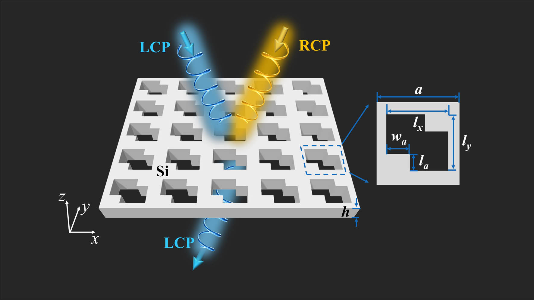
PhCs with a periodical lattice of air holes have been proved to support the symmetry-protected BIC, which corresponds to a polarization vortex in momentum space and is usually achiral [35]. Here, our work demonstrates that the PhC with only reduced geometrical in-plane symmetry can support -BICs with 2D extrinsic and intrinsic chirality. The schematic of our PhC structure is shown in Fig. 1, which consists of a square lattice of air holes in a silicon slab (refractive index ), and the surrounding of the PhC is air. The air hole has a zigzag shape that can be seen as a rectangle with two pieces on both sides cut. This structure has up-down symmetry σ and in-plane rotational symmetry around the axis while lacking in-plane mirror symmetry. Figure 1 schematically shows the totally different optical response to the left circularly polarized (LCP) and right circularly polarized (RCP) waves. In this study, three distinct sets of parameters for the PhC will be designed to systematically investigate the intrinsic and extrinsic chirality excited by the TM mode and the cross-coupling of TE and TM modes.
Figure 1.Schematic illustration of the chiral quasi-BIC photonic crystal slab (PhCs) with perforating holes. The yellow and blue colors represent the RCP and LCP lights, respectively. The inset shows the in-plane unit cell.
First, without loss of generality, we discuss the intrinsic and extrinsic chirality with quasi-BICs for the TM mode. The simulation is performed through the 3D finite element software COMSOL. Since the PhC has mirror symmetry along the propagation direction , we can cut half of the structure in the direction and add the perfect magnetic conductor (PMC)/perfect electric conductor (PEC) boundary condition to calculate the TE/TM eigenmodes, respectively. The bandstructure, -factor, and far-field polarization for the TM mode are shown in Fig. 2. It can be seen that such a structure supports symmetry-protected BICs at point for the band marked as orange and blue colors in Fig. 2(a), while the band with the green color is a leaky mode with a low -factor. Specifically, the insets of Fig. 2(a) show the normalized electric field distribution at point in the plane for . The electric field for the first eigenmode (under the orange triangle) is mainly at the two defects of the structure, while the maximum electric fields of the other two eigenmodes locate at the corner or boundary of the air holes, which indicates that the first eigenmodes will be more sensitive to the in-plane symmetry of the structure; thus, we only consider the far-field polarization of the orange band as shown in the inset of Fig. 2(b). Since the structure has σ and symmetries while the in-plane magnetic field is dominant for this TM mode, which leads to the degree of ellipticity [36], the BIC of the designed PhC structure thereby supports an unusual polarization singularity enclosed by a vortex elliptical eigen polarization with non-vanishing helicity, which indicates that we can achieve -BIC supported chirality by oblique incidence or breaking the in-plane symmetry.
Figure 2.Bandstructures and -factors for TM mode of the PhC with parameters , , , , , and . (a) Optical bands for TM mode of the PhC around point. Insets show the normalized electric fields of the corresponding bands at the point. (b) -factors for the three bands in (a) with the same color. The inset displays the far-field polarization diagram of the orange band in (a).
The above analysis about bandstructure shows the guided resonance (-BIC) of PhC along high symmetry points, and this system dominated by guided resonance can be described by coupled mode theory (CMT) conveniently [37]. CMT has been a powerful tool to predict the chiral response; thus, we aim to apply this theory to get a clear description of the CD for intrinsic/extrinsic chirality, respectively. For clarity, we set the and to represent the intrinsic and extrinsic CD in the following. The 2D intrinsic chirality behavior with -BIC can be explained by temporal coupled mode theory (TCMT). Here, a simplified equation to describe the can be expressed as follows (the detailed calculation process is shown in Appendix B): where is the element of the Jones matrix within the circular basis, the , are subscripted by R, L, which represent the RCP and LCP light, the and are the coupling of the resonances with the incident LCP and RCP light, respectively, is the decay rate due to the radiation, is the resonant frequency, and is the background scattering. If we want to have a maximum at the -BIC resonant frequency from Eq. (1), and should be set to zero. Then the is a unity value. This means that the maximum intrinsic optical chirality requires the resonant mode of PhC to completely couple with LCP light. For RCP light, the transmission of the PhC will only have the background scattering part.
The TCMT for intrinsic chirality has a fixed in-plane , which is not suitable for the extrinsic chirality with the oblique incidence angle (); instead, we apply the coupled-mode theory (CMT) with to investigate the mechanism of strong extrinsic chiral response [38]. CMT offers a new route to interpret extrinsic chirality, which has never been proposed before to the best of our knowledge. The can be expressed as follows (the detailed calculation is shown in Appendix A): where the and represent the coupling of the resonances with the incident LCP and RCP light, respectively, is the decay rate due to the radiation, is the background scattering, and is the wave vector of the resonant radiative mode along the same direction as . In order to have a maximum at the -BIC resonant wave vector for fixed wavelength from Eq. (2), and should be set to zero. Thus, it can be concluded that the maximum CD of extrinsic chirality supported by -BIC mode also requires the selective coupling of LCP/RCP light. To sum up, the key point to acquire strong chirality of PhC is to manipulate the coupling strength of eigenmodes with different helicity.
3. CHIRAL RESPONSE FOR TM EIGENMODE
From the above theoretical analysis for planar PhC supporting BIC, chiral -BIC is expected to be achieved by breaking the BIC symmetry, i.e., tilting the incident angle or breaking the in-plane symmetry. To begin with, the extrinsic chirality is achieved by oblique incidence with the elevation angle and azimuthal angle as shown in Fig. 3(a). Here, the CD is calculated by the formula (the CD in this work is all calculated through this formula), where the transmission . The numerical simulation is performed through COMSOL Multiphysics. In Fig. 3(b), for normal incidence at , the symmetry-protected BIC state cannot couple to the incident wave and, thus, exhibits no chirality. When the incident angle increases along the direction, the peak of CD has a near-unitary value, and the linewidth of the CD gets wider with the continuous increase of incident angle. Specifically, the chiral -BIC has an inverse quadratic relationship with the illumination asymmetry parameter sin() [which can be written as as shown in Fig. 3(d)]. In Fig. 3(d), the -factor of the extrinsic CD spectrum varies from to values as increases, and the peak CD sustains a near-unitary value with the wide range -factor in Fig. 3(b). Therefore, large CD resonances and high -factors (the wide range -factor) can be simultaneously achieved by tuning the incident angle appropriately. Since the structure has symmetry, the incident angle along the negative or positive direction of the axis exhibits the same CD as shown in Fig. 3(b). All the transmittance components and CD are plotted in Fig. 3(c) for , in which shows a peak while the , , and are nearly zero at the resonant wavelength of 1476.5 nm; thus, a maximum CD of 0.98 can be obtained. Note that due to the symmetry of the 2D planar PhC; thus, the extrinsic CD mainly originated from the difference between cross-polarization and . To explicitly show that the high -factor and strong CD resonance can be acquired simultaneously, the transmittance spectra of the Jones matrix and CD with small incident angle are shown in Fig. 8 in Appendix A; particularly, a high -factor (132,777) with strong CD resonance (0.91) appears when . Apart from studying the variation of CD with , the CD spectra with the variation of the azimuthal angle for are also shown in Fig. 9 in Appendix A, and the sign of the CD is consistent with the helicity transition of the far-field polarization diagram in Fig. 2(b). In fact, these numerical transmittance results can be analyzed well through CMT. We fit the , , , and in Fig. 3(c) around the resonant vector using the Fano lineshape equation deduced by CMT for extrinsic chirality in Appendix A, and the fitting results of the transmission are consistent with the numerical calculation as shown in Figs. 7(a)–7(c) in Appendix A. To reveal the resonance mechanism of the extrinsic chirality more specifically, multipole decomposition of the scattering cross sections is performed, and near-field distributions at the resonant -BIC state under RCP excitation are shown in Figs. 13(a)–13(c) in Appendix C, and the detailed calculation method is also proposed in Appendix C. As shown in Fig. 13(a), the electric and magnetic dipoles (ED, MD), electric and magnetic quadrupoles (EQ, MQ), and electric octupoles (EO) all show a peak at the corresponding -BIC chiral resonance mode, while the magnetic octupole (MO) is much weaker. The strongest contribution among them is EO, which is evidenced by the near-field patterns as shown in Fig. 13(c). Only seven magnetic loops with opposite directions can be observed in the plane due to the oblique incidence. Besides, the directions of magnetic loops of the field patterns excited by RCP are different from that of the eigenmode as shown in Fig. 13(b); thus, the RCP light is mostly blocked by the PhC. Meanwhile, the excitation fields are consistent with the eigenmode [-BIC that deviates from the point in Fig. 2(a)], which further proves that the chirality is supported by the -BIC eigenmode. The contribution of the higher-order multiple moments in gammadion nanostructures to chirality has been demonstrated before [39], which extends the chirality beyond the dipole moments. Thus, we can conclude from the multipole analysis that the higher-order multiple moment plays an important role in chirality and the co-excitation of multipole moments is also essential for strong chirality [40].
Figure 3.Extrinsic and intrinsic chiroptical response of the quasi-BIC via pure TM mode. (a), (e) Schematics of the oblique and normal incidence at the PhC. (b) Extrinsic CD spectra with the variation of incident angle for fixed azimuthal angle . (f) Intrinsic CD spectra as a function of the asymmetric parameter . (c), (g) The transmittance spectra , , , and CD were extracted from (b) and (f) for fixed incident angle () and asymmetric parameter (), respectively. The -factors (red dots) and the corresponding fitting curves (black lines) with the variation of (d) illumination asymmetric parameter sin() and (h) geometrical asymmetric parameter .
Except for extrinsic chiral -BICs, we can also acquire intrinsic chiral -BICs by introducing asymmetric parameter to break the in-plane symmetry under normal incidence as schematically shown in Fig. 3(e). In this case, the CD disappears at the as shown in Fig. 3(f), which is due to the dark BIC state. When the geometrical asymmetry is introduced, the BIC state will collapse to a chiral -BIC state, which gives rise to the CD and the linewidth changes with the increase of . Specifically, the -factor of the chiral -BICs also decays as when the geometrical symmetry is broken as shown in Fig. 3(h). In Fig. 3(h), the -factor of the intrinsic CD spectrum increases from to values as decreases, and the peak CD also sustains near-unitary value with the wide range -factor in Fig. 3(f). This shows the wide tunability of the -factor with a large CD through the asymmetric parameter . All transmittance components and CD are plotted in Fig. 3(g) for and show a similar trend as shown in Fig. 3(c). The maximum CD for the intrinsic chirality is 0.92 at 1482.8 nm. In addition, with small asymmetric parameters , the transmission spectra of all Jones matrix elements and the CD spectrum are also shown in Fig. 11 of Appendix B. The CD spectrum at the resonance is extremely sharp—for example, the -factor is 986,846 with the maximum for . The transmission spectra of intrinsic chirality can also be well analyzed by the TCMT proposed above. The simulation results shown in Fig. 3(g) are fitted according to the theory proposed in Appendix B, which are also in good agreement with the analytical calculation of TCMT around the resonant wavelength as shown in Figs. 10(a)–10(c) in Appendix B. To show the evolution of the circular polarization eigenstates with different , the far-field polarization patterns are provided in Fig. 12 in Appendix B. The circular polarization states will move away from the point with the increase of . Moreover, the multipole decomposition for the intrinsic chirality is performed to study the origin of the chirality as well. Since the intrinsic chiral response is based on the same chiral BIC state of TM mode as the extrinsic chirality above, the multipole contributions of intrinsic chirality are similar to that of extrinsic chirality. As shown in Fig. 13(d), the ED, MD, EQ, MQ, and EO are all excited at the corresponding -BIC chiral resonance mode. Four pairs of magnetic loops with opposite directions can be observed in the plane at 1482.8 nm as shown in Fig. 13(f), which proves the presence of the strongest EO. Meanwhile, the excited field pattern is the same as the eigen -BIC mode at point but with the opposite magnetic loops as shown in Figs. 13(e) and 13(f). Above all, the same conclusion can be made: the co-excitation of electric/magnetic multipoles is indispensable for both extrinsic/intrinsic chirality.
4. EXTRINSIC CHIRAL RESPONSE FOR THE COUPLING OF TE AND TM MODES
Apart from the extrinsic and intrinsic chirality for the pure TM eigenmode above, the coupling of TE and TM modes can also be used to obtain the giant chiroptical response [30]. It is possible for the non-orthogonal TE-like and TM-like mode degeneracy to appear when the illumination symmetry and in-plane geometrical symmetry are broken for the PhC. Thus, in the following two parts, we aim to investigate the chiroptical response that relies on both TE and TM polarizations. Here, the geometrical parameter is changed to , , , , , and . To begin with, we plot the 3D bandstructure of the TE mode (enclosed by the green line) and TM mode (enclosed by the red line) in Fig. 4(a), and the colormap shows the -factors, from which we can see that the -factors tend to infinity at point ( and ); thus, these two modes both have symmetry-protected BIC states at the point. The two yellow lines indicate the hybridization wavelengths of the TE and TM modes in space. Since the degeneration points are located away from point, we can expect giant chirality to show up at oblique incidence in accordance with the interaction points in space. Here, we choose two points in the yellow lines in Fig. 4(a) marked by the blue dot (, ) and the purple dot (, ), respectively, to study the chiroptical response at the hybridization points. The projection relationship between the in-plane wave vector of the PhC and the incident angle is [41]; thus, the incident angle can be written as . Here, is the wave vector in air. Figure 4(b) shows the absolute difference of the eigen-wavelength of the TE and TM modes, in which . Clearly, the black regions denote the overlap of the two modes in space, and the degeneration eigen-wavelengths of the and points are also shown in Fig. 4(b).
Figure 4.Extrinsic chirality with parameters , , , , , via the degeneration of TE and TM modes. (a) Three-dimensional (3D) optical bands of the TE (3D surfaces surrounded by the green line) and TM modes (3D surfaces surrounded by the red line). The two yellow lines indicate the interaction eigen-wavelength of the TE and TM modes. The blue and yellow dots are chosen from the yellow lines. (b) The absolute difference of the eigen-wavelength of TE and TM modes in (a), with the blue and purple dots corresponding to eigen-wavelength 1597.2 nm and 1598.6 nm, respectively. (c) and (d) are the optical CD spectra corresponding to the blue and purple dots for fixed azimuthal angle . (e) and (f) are the transmittance spectra , , , , and CD at oblique incidence angles corresponding to the blue and purple dots in (a) and (b).
To calculate the CD at the two points in space that have been marked in Fig. 4(a), the incident light is inclined along the and vectors in Fig. 4(b) for the fixed azimuthal angle and , respectively. In fact, the maximum chiroptical response may slightly deviate from the degeneracy point for continuum coupling of non-orthogonal TE-like and TM-like modes [30]. Thus, to begin with, the incident light is inclined along the and vectors in Figs. 4(c) and 4(d) for the fixed azimuthal angle and , respectively, to study the maximum CD near the two points. The CD in Figs. 4(c) and 4(d) vanishes at the normal incidence due to the symmetry-protected BIC states for TE and TM modes, respectively, in Fig. 4(a). We can observe that the upper and lower bands of the CD will converge with the increase of and exhibit a maximum CD at a certain inclined angle. Then the transmission and CD spectra are displayed in Figs. 4(e) and 4(f) for and [corresponding to the maximum CD in Figs. 4(c) and 4(d)], respectively. In Fig. 4(e), the -factor for the CD spectrum is 258, and the peak of the CD is at 1596.8 nm, which is almost the same as the eigen-wavelength of the (1597.2 nm) point. For the (the corresponding eigen-wavelength is 1598.6 nm) point, the -factor for the CD spectrum is 528, and maximum CD is 0.997 at 1598.7 nm in Fig. 4(f); the wavelength of the excitation -BIC mode is also very close to the eigen-wavelength. These results comprehensively show that the giant extrinsic CD arises from the hybridization of TE and TM modes at oblique incidence.
The above extrinsic chirality exploits TE and TM coupling. To further understand the chiral resonance supported by the TE and TM modes, the multipole scattering cross sections and the near-field patterns are shown in Fig. 14 in Appendix C. Electric and magnetic multipoles (up to octupoles) are all excited at the peak of CD, which shares the same mechanism of the chirality under pure TM mode: co-excitation of multipoles. The two main multipole contributions are vertical EO and parallel EQ, which are derived from the TM mode and TE mode, respectively.
5. INTRINSIC CHIRAL RESPONSE FOR THE COUPLING OF TE AND TM MODES
The remarkable intrinsic chirality in a quasi-two-dimensional structure has potential applications in quantum optics and optomechanics [30]. Inspired by this work, we expect that the planar PhC also supports the intrinsic chiral response by engineering both the TE and TM modes through breaking the in-plane symmetry. The geometrical parameters are the same as Fig. 4 with a different thickness . Figure 5(a) shows the eigen-wavelength and -factors at point of the TE and TM modes with the variation of asymmetric parameters . For , the TM mode has a BIC state for an infinite -factor at point, while the TE mode has a low -factor state due to the field radiation to the external environment. The eigen-wavelengths of the TE and TM modes get closer with the increase of the , and we can see clearly that the two modes degenerate at in Fig. 5(a). The corresponding 2D bandstructure of the PhC is also shown in Fig. 5(b), where we can see the degeneration of TE and TM modes at point at .
Figure 5.Intrinsic chirality of TE and TM coupling modes with parameters , , , , , . (a) The black lines with circle/square shape are the eigen-wavelength of TM/TE mode at point, respectively, as a function of , and the red lines are the corresponding -factors of the modes. (b) Bandstructure of the PhC with near the vicinity of point. (c) CD for different geometrical parameters . (d) Evolution of the TE and TM eigenmodes at the point with the variation of the asymmetric parameter . (e) Electromagnetic (EM) field distribution under LCP excitation as a function of the asymmetric parameter .
Figure 5(c) shows the evolution of CD spectra by varying asymmetric parameter . Specifically, the simulated -factors and the peaks of the CD spectrum here are 7611/−0.825 (), (), (), and (), respectively. It is shown that the magnitude of CD at resonances would become larger when the eigen-wavelengths of TE and TM modes get close to each other due to parameter increase, which reveals that the giant CD arises from the co-excitation of the TE and TM modes. When the symmetry is broken, the TE-like and TM-like modes are not orthogonal with each other anymore; thus, they can couple to give rise to the chiral response.
Furthermore, to illustrate the TE and TM eigenmodes coupling process with , we show the evolution of TE/TM eigenmodes profiles and the electromagnetic (EM) field profiles excited by LCP light in Figs. 5(d) and 5(e). The EM field in Figs. 5(d) and 5(e) is extracted at the plane for . The TE mode is a low- mode, and its mode profiles remain constant with the variations of , as shown in the upper row of Fig. 5(d). In contrast, the TM mode exhibits a different behavior: both the maximum electric and magnetic fields tend to concentrate near the cutting area as increases, as illustrated in the lower row of Fig. 5(d). At the left panels in Fig. 5(e), the electric and magnetic field illuminated by LCP is the same as the profiles of the TM eigenmode for , which is due to the excitation of pure TM mode. The CD peak is only for . The magnetic field is dominated by the eigenmode profile of the TM mode with the increase of , while the electric fields become similar to the eigenmode profile of the TE mode as shown in the right panels in Fig. 5(e). The mixture of the excitation EM fields denotes the co-excitation of the TE and TM modes.
To further understand the origin of the intrinsic chiral response empowered by the -BIC TM mode and leaky TE mode above, the normalized multipole contributions for different under LCP excitation are shown in Figs. 15(a)–15(d) in Appendix C. Note that the EQ in Figs. 15(a) and 15(b) is dominant; however, this chiral response is weak due to the pure excitation of the EQ without magnetic multipoles. The dotted lines in Fig. 15 correspond to the position of the CD peak in Fig. 5(c), and the multipole contributions at the wavelengths of the CD peak are extracted and normalized, respectively, in Fig. 16 in Appendix C. The maximum multipole contribution is MQ, which is supported by the TM eigenmode. Meanwhile, the proportions of EO, ED, and EQ increase with the variation of the parameters. It can be concluded that the giant intrinsic CD is due to the mixture excitation of the multipoles from both Figs. 15 and 16, which originated from TE and TM degeneracy.
6. CONCLUSION
In summary, we have designed a 2D PhC with reduced in-plane symmetry, which exhibits a giant intrinsic and extrinsic -BIC chiroptical response. This is achieved through engineering BIC states in PhC for the pure TM mode or TE and TM cross-coupling mode. By adjusting the incident angle or in-plane asymmetric parameters, this PhC exhibits near-unity extrinsic/intrinsic CD (maximum ) and high -factors supported by chiral -BICs for the pure TM mode. With the increase of the thickness of the slab, the mixture of TE and TM modes tends to appear when the illumination symmetry and in-plane symmetry are broken for the PhC, which allowed for the achievement of the ultra-strong extrinsic and intrinsic -BIC chirality. Based on the TCMT, we revealed two analytical expressions of CD for the chiral -BIC response, which can be applied to predict and analyze CD well. Furthermore, the giant chiroptical responses have been proved to originate from the co-excitation of both electric/magnetic multipoles. In particular, higher-order (up to octupole) multipoles are also essential for the strong chiroptical response. Our work demonstrates that planar PhC can support giant 2D chirality via different polarization eigenmodes, which may provide a new paradigm for the future design of 2D chiral metamaterials. Additionally, this chiral platform with high -factors also has potential applications in chiral lasing, chiral sensing, and enantiomer separation.
APPENDIX A: COUPLED-MODE THEORY FOR EXTRINSIC CHIRAL Q-BICS
Extrinsic chirality requires an oblique incidence angle (); thus, we apply coupled-mode theory (CMT) with proposed by Wang et al. [38], and the equation of CMT can be written as where is the complex amplitude of the oscillating eigenmode, is the background scattering matrix, is the coupling matrix between the resonances with the incident and outgoing waves, is the group velocity of the radiative mode, is the decay rate due to the radiation, is the in-plane position whose direction is parallel to , and is the wave vector of the resonant radiative mode along the same direction as .
The and are the output and input waves from two ports (port I and port II) as shown in Fig. 6(a), and the subscript L/R means the LCP/RCP light. is the background scattering matrix for the direct transport process and can be written as [20] where the subscripts of and (, L, , L) indicate the RCP and LCP, respectively, and the , , , and can be written as , , , and , respectively. The coupling matrix in Eq. (A1) can also be written as where the elements in Eq. (A3) are the coupling coefficients of the resonant mode with LCP/RCP light from port I/II. needs to satisfy the following relationship considering the space-reversal process condition and the energy conservation of the system:
Figure 6.(a) Schematic of the CMT for extrinsic optical chirality along the positive direction. (b) Schematic of the TCMT for intrinsic optical chirality.
Figure 8.Transmittance spectra , , , , and CD with small incident angle . The -factor and the maximum CD are 132,777/0.91, 5339/0.93, and 1379/0.94 for , 2°, and 4°, respectively.
Due to the mirror symmetry of the PhC, the coupling between the eigenmode and the LCP and RCP light at two ports is the same, which can be written as Meanwhile, for this planar PhC, the cross-polarization coupling of the eigenmode with port I/II should be the same; thus, we have
Combining Eqs. (A4) and (A6), we can get the relationship of and , Note that the and are complex numbers, according to Eq. (A7), and the and can be written as
Further considering , we can have the expression of ,
Substituting the Eqs. (A2), (A3), and (A6) into Eq. (A9), we have the form of as follows:
Equation (A10) can also be written as the Fano line-type function, where
We mainly consider the , , , and in the main text; thus, the corresponding parameters are given as follows:
Equations (A10) and (A11) have , and the group velocity along direction is for the orange band in the Fig. 2(a); thus, for the along positive direction, we have , and the transmission of can be written as
We can use Eq. (A14) to fit the , , , and of Fig. 3(c) as shown in Figs. 7(a)–7(c). The transmittance spectra of the Jones matrix and CD with small incident angle are shown in Fig. 8. If the CD is defined as , we only consider the incident LCP/RCP waves from port I, and substituting Eqs. (A7) and (A10) into the expression of CD, the extrinsic CD can be written as
Since , the sign of will not influence the expression in Eq. (A15), and Eq. (A15) can be written as
In addition, the extrinsic chiroptical response can also be tuned through the azimuthal angle as shown in Fig. 9.
APPENDIX B: TEMPORAL COUPLED-MODE THEORY FOR INTRINSIC CHIRAL Q-BICS
Since the PhC owns symmetry, for intrinsic chirality with normal incidence, the main equation of TCMT is [37] where is the complex amplitude of the oscillating eigenmode, is the mode’s resonant frequency, is the decay rate due to the radiation, is the scattering matrix, and is the coupling matrix between the resonances with the incident and outgoing waves. For circularly polarized light, and are the input and output waves from two ports (port I and port II), respectively, as shown in Fig. 6(b), and the subscript L/R represents the LCP/RCP light. The and will have the same form as in Eqs. (A2) and (A3) and are shown in the following [20]: where the subscripts of and (, L, , L) indicate the RCP and LCP, respectively, and the , , , and can be written as , , , and , respectively. in Eq. (B2) needs to satisfy the relationship due to time-reversal symmetry.
The coupling matrix in Eq. (B1) can be written as where the elements in Eq. (B3) are the coupling coefficients of the resonant mode with LCP/RCP light from port I/II. needs to satisfy the following relationship due to time-reversal symmetry and the energy conservation:
Due to the mirror symmetry of the PhC, the coupling between the eigenmode and the LCP and RCP light at two ports is the same, which can be written as Meanwhile, for this planar PhC, the cross-polarization coupling of the eigenmode with port I/II should be the same; thus, we have
Substituting Eq. (B6) into the first equation in Eq. (B4), we have Note that the and are complex numbers, according to Eq. (B7), and the and can be written as
Figure 9.CD spectra with the variation of azimuthal angle and wavelength at .
Figure 11.Transmittance spectra , , , , and CD with small asymmetric parameters . The -factor and the maximum CD are 986846/0.94, 39721/0.92, and 9147/0.92 for , 10 nm, and 20 nm, respectively.
Figure 12.Far-field polarization diagrams in momentum space with different . The red/blue color represents the right-handed/left-handed polarization states. The circular polarization states are marked with red/blue dots.
Figure 13.Multipole contributions of the PhC (a) under oblique incidence (, , and ) and (d) normal incidence (, , and ) for TM eigenmode. The electromagnetic eigenmode for the (b) wave vector along direction and (e) at point; here, the blue and red circles indicate the magnetic loops. (c), (f) Corresponding component of electric field at 1476.5 nm and 1482.8 nm, respectively, under RCP excitation. The black vectors are magnetic fields (, ). The electric field patterns are extracted from plane at .
From Eq. (B1) and considering , we can have the expression of ,
Substituting the Eqs. (B2), (B3), and (B6) into Eq. (B9), we have the form of as follows:
Note that the transmission of the same helicity is same at the same port in Eq. (B10). Moreover, Eq. (B10) can be written as the Fano line-type function, where
The parameters , , , in Eq. (B12) have the same form as those in Eq. (A13). We can get the expression of reflection/transmission from Eqs. (B11) and (B12) as follows:
We can use Eq. (B13) to fit the , , , and of Fig. 3(g) in the main text around the resonant peak as shown in Figs. 10(a)–10(c). Furthermore, we can get the similar expression of intrinsic CD as Eq. (A16),
In addition, the far-field polarization diagrams in momentum space with different asymmetric parameters are shown in Fig. 12.
APPENDIX C: MULTIPOLE CONTRIBUTIONS OF THE PHC
The multipole scattering cross sections under RCP/LCP incidence for are shown in this section, which is helpful for understanding the origin of the chiral response. The spherical multipole scattering cross sections of the PhC under LCP/RCP excitation are calculated through COMSOL Multiphysics. The periodical boundary condition is utilized, and the two perfectly matched layers are added at the ports. The electric field in the unit cell of the PhC is extracted and the following equation is used to get the scattering current density: and the electric and magnetic multipole coefficients can be calculated as [42] where is the electric field amplitude, is the impedance of the free space, are the Riccati–Bessel functions, and are their first and second derivatives with respect to the argument , represents the associated Legendre polynomials, and the electric and magnetic multipole (dipole for , quadrupole for , octupole for ) coefficients can be written as
Figure 14.Multipole contributions of the PhC under oblique incidence at (a) and (d) points in Fig. 4(a) under LCP and RCP excitation, respectively; the black dotted lines indicate the peak of the CD. Electric field distributions at the peak of CD are extracted from (b), (e) plane for and (c), (f) plane for . The black vectors are magnetic fields (, ); here, the blue and red circles indicate the magnetic loops.
Figure 16.Normalized multipole contributions of the PhC under LCP excitation at the wavelength of the peak of the CD for , 40 nm, 70 nm, and 90 nm, respectively.