• Acta Optica Sinica
  • Vol. 39, Issue 12, 1222001 (2019)
Ruifeng Ming1, Yayi Wei1、2、*, and Lisong Dong2
Author Affiliations
  • 1School of Microelectronics, University of Chinese Academy of Sciences, Beijing 100049, China
  • 2Institute of Microelectronics of the Chinese Academy of Sciences, Beijing 100029, China
  • show less
    DOI: 10.3788/AOS201939.1222001 Cite this Article Set citation alerts
    Ruifeng Ming, Yayi Wei, Lisong Dong. Influence of Optical System Aberration on Critical Dimension of EUV Lithography Imaging[J]. Acta Optica Sinica, 2019, 39(12): 1222001 Copy Citation Text show less
    Wavefront distributions of four typical aberrations and test diagrams
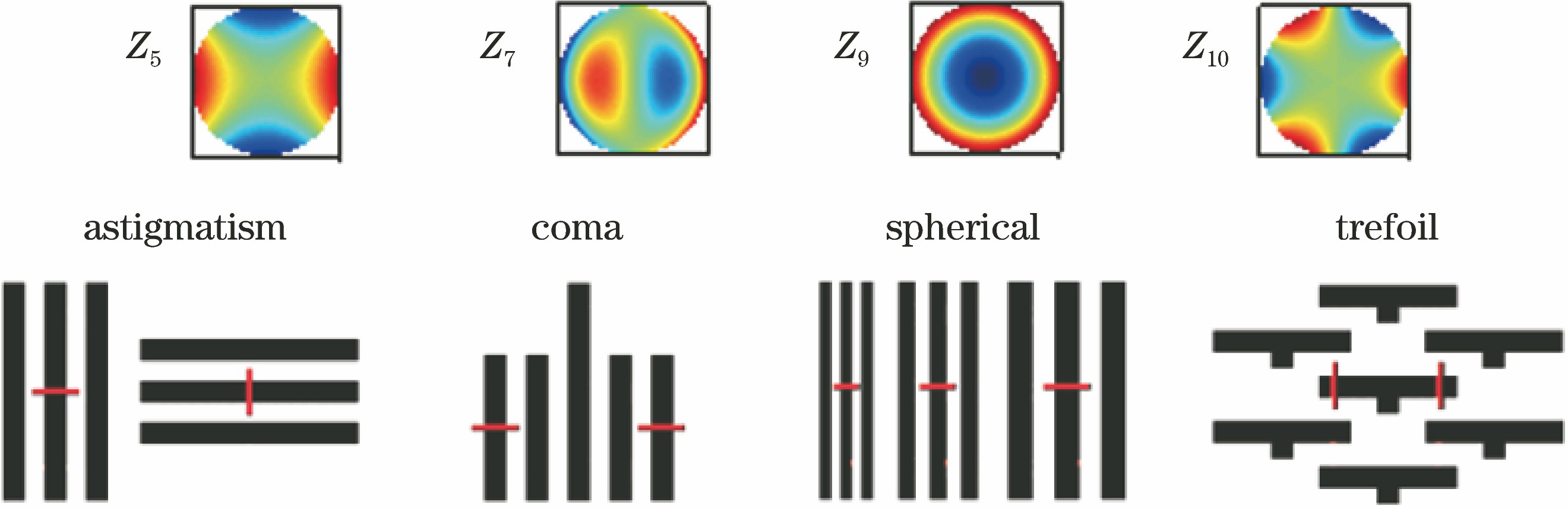
    Fig. 1. Wavefront distributions of four typical aberrations and test diagrams
    Variation of critical dimension with focus length of lines with different orientations under different aberrations. (a) Horizontal line; (b) vertical line; (c) critical dimension differences of horizontal and vertical lines
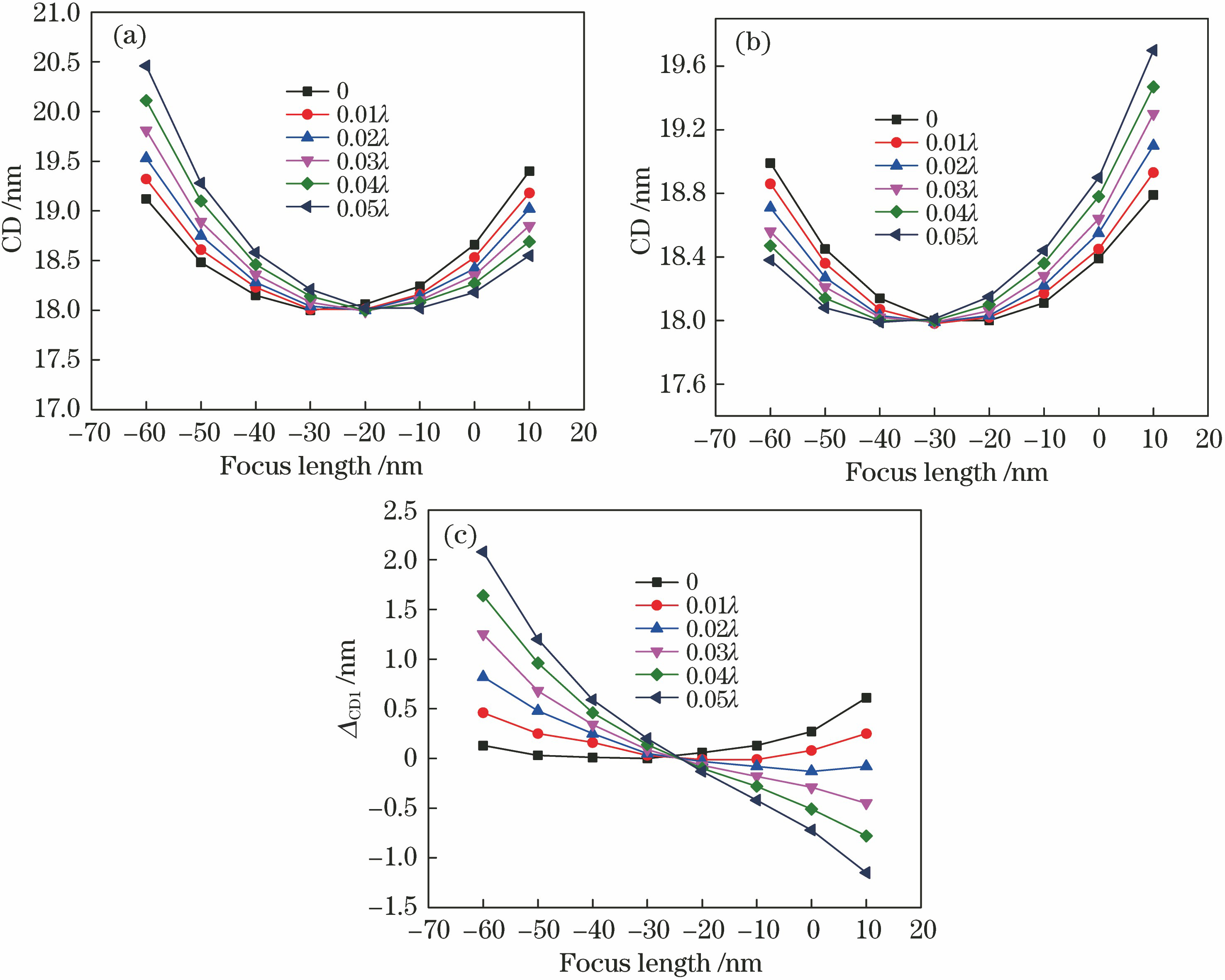
    Fig. 2. Variation of critical dimension with focus length of lines with different orientations under different aberrations. (a) Horizontal line; (b) vertical line; (c) critical dimension differences of horizontal and vertical lines
    Variation of critical dimension with focus length of short lines with different aberrations. (a) 1st line; (b) 5th line; (c) critical dimension differences of 1st and 5th lines
    Fig. 3. Variation of critical dimension with focus length of short lines with different aberrations. (a) 1st line; (b) 5th line; (c) critical dimension differences of 1st and 5th lines
    Best focus length varying with pitch under different aberrations
    Fig. 4. Best focus length varying with pitch under different aberrations
    Critical dimensions of left and right ends of horizontal short line varying with focus length under different aberrations. (a) Left end; (b) right end; (c) difference of critical dimensions of left and right ends
    Fig. 5. Critical dimensions of left and right ends of horizontal short line varying with focus length under different aberrations. (a) Left end; (b) right end; (c) difference of critical dimensions of left and right ends
    Critical dimension varying with focus length of test structure corresponding to Z5 model. (a) Horizontal line; (b) vertical line
    Fig. 6. Critical dimension varying with focus length of test structure corresponding to Z5 model. (a) Horizontal line; (b) vertical line
    Critical dimension varying with focus length of test structure corresponding to Z7 model. (a) 1st line; (b) 2nd line
    Fig. 7. Critical dimension varying with focus length of test structure corresponding to Z7 model. (a) 1st line; (b) 2nd line
    Critical dimension varying with focus length of test structure corresponding to Z10 model. (a) Left end of horizontal short line; (b) right end of horizontal short line
    Fig. 8. Critical dimension varying with focus length of test structure corresponding to Z10 model. (a) Left end of horizontal short line; (b) right end of horizontal short line
    Materialnk
    MultilayerMo0.921080.00644
    Si0.999320.00183
    Ta6N40.930250.04338
    SOC (soft on chip)1.30.4
    Resist0.980.00269
    ARC1.341
    Table 1. Optical parameters of partial materials
    Ruifeng Ming, Yayi Wei, Lisong Dong. Influence of Optical System Aberration on Critical Dimension of EUV Lithography Imaging[J]. Acta Optica Sinica, 2019, 39(12): 1222001
    Download Citation