• Journal of Infrared and Millimeter Waves
  • Vol. 40, Issue 3, 347 (2021)
Luan-Feng GAO, Yu-Lu HU*, Xiao-Fang ZHU, Quan HU, Jian-Qing LI, and Bin LI
Author Affiliations
  • School of Electronic Science and Engineering, University of Electronic Science and Technology of China, Chengdu 610054, China
  • show less
    DOI: 10.11972/j.issn.1001-9014.2021.03.011 Cite this Article
    Luan-Feng GAO, Yu-Lu HU, Xiao-Fang ZHU, Quan HU, Jian-Qing LI, Bin LI. Simulation and cold test of integrated multi-beam TWT with multi-corrugated waveguide SWS[J]. Journal of Infrared and Millimeter Waves, 2021, 40(3): 347 Copy Citation Text show less
    (a) The perspective for the 3D model of the multi-corrugated waveguide SWS,(b) the top view with dimensional parameters of MCW SWS
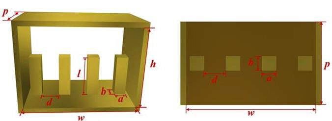
    Fig. 1. (a) The perspective for the 3D model of the multi-corrugated waveguide SWS,(b) the top view with dimensional parameters of MCW SWS
    Dispersion and coupling impedance characteristics with the variation of geometric size (a) the pillar length l, (b) the waveguide width w, (c) the period of MCW p
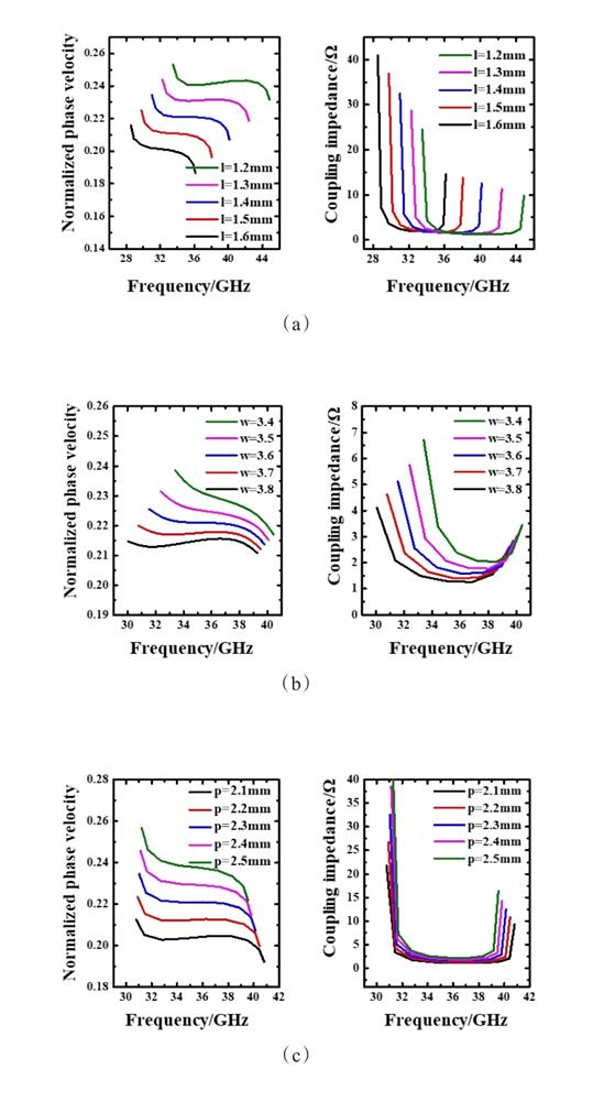
    Fig. 2. Dispersion and coupling impedance characteristics with the variation of geometric size (a) the pillar length l, (b) the waveguide width w, (c) the period of MCW p
    The dispersion curve and coupling impedance of the MCW with dimensions in Table I. note: the beam line of 12.9 kV is superimposed
    Fig. 3. The dispersion curve and coupling impedance of the MCW with dimensions in Table I. note: the beam line of 12.9 kV is superimposed
    the 3D model and the assembly sketch of the MCW SWSs
    Fig. 4. the 3D model and the assembly sketch of the MCW SWSs
    Fabricated MCW SWS with input-output coupler
    Fig. 5. Fabricated MCW SWS with input-output coupler
    the photograph of the vector network analyzer and the tested result
    Fig. 6. the photograph of the vector network analyzer and the tested result
    comparison between simulation and measured S-parameters of the fabricated MCW SWSs
    Fig. 7. comparison between simulation and measured S-parameters of the fabricated MCW SWSs
    Model of the three-beam MCW circuit in CST PARTICLE STUDIO
    Fig. 8. Model of the three-beam MCW circuit in CST PARTICLE STUDIO
    the variation of input and output signal with time in the frequency of 34 GHz
    Fig. 9. the variation of input and output signal with time in the frequency of 34 GHz
    Frequency spectrum of the output signal
    Fig. 10. Frequency spectrum of the output signal
    Energy distribution of electron beam along the transmission direction(z)
    Fig. 11. Energy distribution of electron beam along the transmission direction(z)
    the output power and gain versus frequency for the MCW TWT
    Fig. 12. the output power and gain versus frequency for the MCW TWT
    the electronic efficiency of the MCW TWT in the 29~39 GHz frequency band
    Fig. 13. the electronic efficiency of the MCW TWT in the 29~39 GHz frequency band
    SymbolQuantityValue(mm)
    aThe width of the pillar0.4
    bThe thickness of the pillar0.4
    dThe distance between pillars0.6
    lThe length of the pillar1.4
    hThe high of the waveguide2.6
    pThe period of the SWS2.3
    wThe width of the waveguide3.6
    Table 1. Dimension of The MCW SWS
    SWSVoltage(kV)Current(mA)Period number in BWIOutput power(maximum)Electronic efficiency(maximum)Gain(maximum)
    MCW12.967*350132.8 W5.12%41.2 dB
    DCW122008029 W1.2%25 dB
    Table 2. Comparison of the DCW[17] and the three-Beam MCW circuit
    Luan-Feng GAO, Yu-Lu HU, Xiao-Fang ZHU, Quan HU, Jian-Qing LI, Bin LI. Simulation and cold test of integrated multi-beam TWT with multi-corrugated waveguide SWS[J]. Journal of Infrared and Millimeter Waves, 2021, 40(3): 347
    Download Citation