• Photonics Research
  • Vol. 6, Issue 6, 630 (2018)
Jinhua Li and Xiangdong Zhang*
Author Affiliations
  • Beijing Key Laboratory of Nanophotonics & Ultrafine Optoelectronic Systems, School of Physics, Beijing Institute of Technology, Beijing 100081, China
  • show less
    DOI: 10.1364/PRJ.6.000630 Cite this Article Set citation alerts
    Jinhua Li, Xiangdong Zhang. Electric field tunable strong transverse light current from nanoparticles embedded in liquid crystal[J]. Photonics Research, 2018, 6(6): 630 Copy Citation Text show less
    Geometry of the scattering problem for an ensemble of N spheres embedded in an LC cell. Here, θ and φ denote the polar and azimuthal angles of the wave vector k→, respectively. The α represents tilt angle between the principal axis of the nematic LC molecule and the x axis.
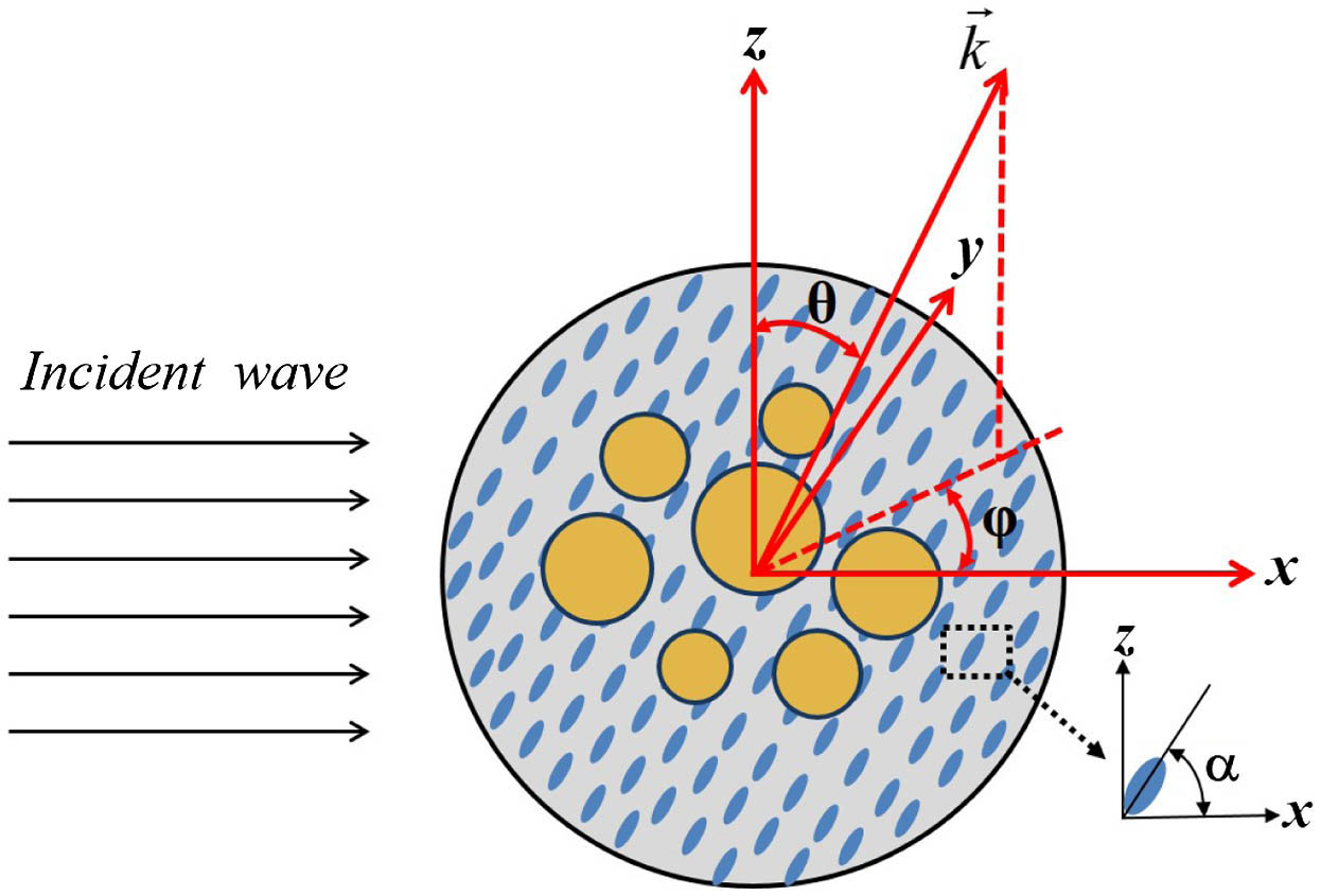
    Fig. 1. Geometry of the scattering problem for an ensemble of N spheres embedded in an LC cell. Here, θ and φ denote the polar and azimuthal angles of the wave vector k, respectively. The α represents tilt angle between the principal axis of the nematic LC molecule and the x axis.
    (a) Transverse asymmetry parameter gy and (b) scattering efficiency Qs as a function of incident frequency at external voltage V/Vc=1.0239 in the non-centrosymmetric case. (c) and (d) show the results in the centrosymmetric case. The geometrical parameters of two structures as shown in the inset of (b) and (d) are taken as R=50 nm, r=13 nm, and dy=20 nm. Red, blue, and green lines represent left circularly polarized, right circularly polarized, and linearly polarized incident waves, denoted by LCP, RCP, and LP10 with (pθ,pφ)=1/2(1,i), (pθ,pφ)=1/2(1,−i), and (pθ,pφ)=(1,0), respectively. The black lines denote the results for the pure LC cell, with r=0 nm illuminated by the left circularly polarized wave. The A, B, and C points in (b) indicate the values of gy and Qs in Figs. 3(a)–3(c), respectively.
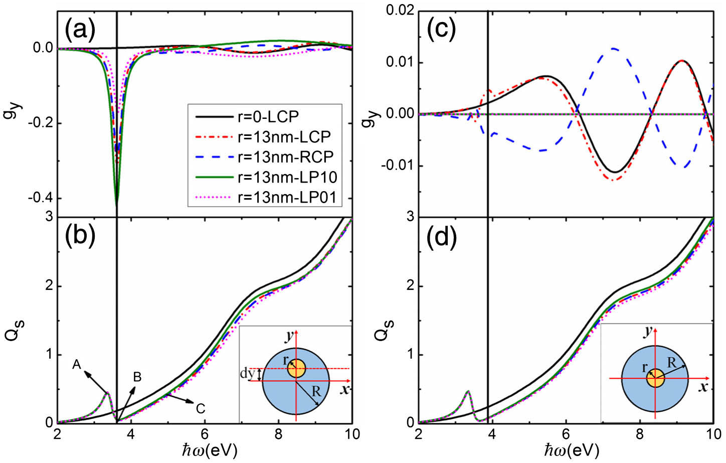
    Fig. 2. (a) Transverse asymmetry parameter gy and (b) scattering efficiency Qs as a function of incident frequency at external voltage V/Vc=1.0239 in the non-centrosymmetric case. (c) and (d) show the results in the centrosymmetric case. The geometrical parameters of two structures as shown in the inset of (b) and (d) are taken as R=50  nm, r=13  nm, and dy=20  nm. Red, blue, and green lines represent left circularly polarized, right circularly polarized, and linearly polarized incident waves, denoted by LCP, RCP, and LP10 with (pθ,pφ)=1/2(1,i), (pθ,pφ)=1/2(1,i), and (pθ,pφ)=(1,0), respectively. The black lines denote the results for the pure LC cell, with r=0  nm illuminated by the left circularly polarized wave. The A, B, and C points in (b) indicate the values of gy and Qs in Figs. 3(a)3(c), respectively.
    In the x–y plane, the distributions of the electric field intensity (a), (b), and (c) correspond to the points A, B, and C in Fig. 2(b), respectively. (d), (e), and (f) show the time-average scattering Poynting vector distributions of points A, B, and C separately.
    Fig. 3. In the xy plane, the distributions of the electric field intensity (a), (b), and (c) correspond to the points A, B, and C in Fig. 2(b), respectively. (d), (e), and (f) show the time-average scattering Poynting vector distributions of points A, B, and C separately.
    (a) Transverse asymmetry parameter gy as a function of incident frequency. Black solid and red dashed lines represent two linearly polarized incident waves, denoted by LP10 and LP01 with (pθ,pφ)=(1,0) and (pθ,pφ)=(0,1), respectively. The blue square line represents the LP10 result calculated using COMSOL Multiphysics. (b), (c) Electric field intensity for the points A and B, respectively, in (a). (d), (e) The corresponding time-average scattering Poynting vector. The asymmetric chain structure is shown in the inset of (a). The value of external voltage is V/Vc=1.0239. The geometrical parameters are described in the text.
    Fig. 4. (a) Transverse asymmetry parameter gy as a function of incident frequency. Black solid and red dashed lines represent two linearly polarized incident waves, denoted by LP10 and LP01 with (pθ,pφ)=(1,0) and (pθ,pφ)=(0,1), respectively. The blue square line represents the LP10 result calculated using COMSOL Multiphysics. (b), (c) Electric field intensity for the points A and B, respectively, in (a). (d), (e) The corresponding time-average scattering Poynting vector. The asymmetric chain structure is shown in the inset of (a). The value of external voltage is V/Vc=1.0239. The geometrical parameters are described in the text.
    Asymmetric chain structure with R=50 nm is illuminated by the linearly polarized wave LP10. (a) Transverse asymmetry parameter gy as a function of the ratio r/R at external voltages V/Vc=1.0239. Black, red, and blue lines represent the incident frequencies ℏω=3.85 eV, ℏω=4.15 eV, and ℏω=4.85 eV, respectively. (b) gy as a function of the external voltage V/Vc when the incident wave frequency is ℏω=4.0 eV. Black square, red circle, blue triangle, and green triangle lines represent Ag sphere radius r=11, 12, 13, and 14 nm, respectively.
    Fig. 5. Asymmetric chain structure with R=50  nm is illuminated by the linearly polarized wave LP10. (a) Transverse asymmetry parameter gy as a function of the ratio r/R at external voltages V/Vc=1.0239. Black, red, and blue lines represent the incident frequencies ω=3.85  eV, ω=4.15  eV, and ω=4.85  eV, respectively. (b) gy as a function of the external voltage V/Vc when the incident wave frequency is ω=4.0  eV. Black square, red circle, blue triangle, and green triangle lines represent Ag sphere radius r=11, 12, 13, and 14 nm, respectively.
    (a) Transverse asymmetry parameter gy as a function of incident frequency. The red and black lines indicate the centrosymmetry and non-centrosymmetry cases, respectively. (b), (c) and (d) Electric field intensity for the points A, B, and C, respectively, in (a). (e), (f), and (g) Corresponding time-average scattering Poynting vector. The triangle structure is shown in the inset of (a). The value of external voltage is V/Vc=1.0239. The radii of the Ag spheres are r=20 nm; other parameters are described in the text.
    Fig. 6. (a) Transverse asymmetry parameter gy as a function of incident frequency. The red and black lines indicate the centrosymmetry and non-centrosymmetry cases, respectively. (b), (c) and (d) Electric field intensity for the points A, B, and C, respectively, in (a). (e), (f), and (g) Corresponding time-average scattering Poynting vector. The triangle structure is shown in the inset of (a). The value of external voltage is V/Vc=1.0239. The radii of the Ag spheres are r=20  nm; other parameters are described in the text.
    Transverse asymmetry parameter gy as a function of (a) the ratio r/R and (b) external voltages for the triangle system as shown in the inset of (b). The linearly polarized wave LP10 propagates along the x axis. Three Ag spheres are tangent to the LC cell. The other parameters are described in the text. (a) Solid lines and dashed lines represent the external voltages V/Vc=1.0239 and 1.9529, respectively. Black, red, and blue curves denote the incident frequencies ℏω=3.6 eV, ℏω=3.63 eV, and ℏω=3.66 eV, respectively. (b) Green square, orange circle, and pink triangle lines represent the incident frequencies ℏω=3.61 eV, ℏω=3.63 eV, and ℏω=3.65 eV, respectively. The other parameters in (b) are consistent with the vertical light green line in (a).
    Fig. 7. Transverse asymmetry parameter gy as a function of (a) the ratio r/R and (b) external voltages for the triangle system as shown in the inset of (b). The linearly polarized wave LP10 propagates along the x axis. Three Ag spheres are tangent to the LC cell. The other parameters are described in the text. (a) Solid lines and dashed lines represent the external voltages V/Vc=1.0239 and 1.9529, respectively. Black, red, and blue curves denote the incident frequencies ω=3.6  eV, ω=3.63  eV, and ω=3.66  eV, respectively. (b) Green square, orange circle, and pink triangle lines represent the incident frequencies ω=3.61  eV, ω=3.63  eV, and ω=3.65  eV, respectively. The other parameters in (b) are consistent with the vertical light green line in (a).
    Jinhua Li, Xiangdong Zhang. Electric field tunable strong transverse light current from nanoparticles embedded in liquid crystal[J]. Photonics Research, 2018, 6(6): 630
    Download Citation