• Photonics Research
  • Vol. 10, Issue 12, 2786 (2022)
Zeng-Xing Liu1、* and Yong-Qing Li1、2
Author Affiliations
  • 1School of Electronic Engineering & Intelligentization, Dongguan University of Technology, Dongguan 523808, China
  • 2Department of Physics, East Carolina University, Greenville, North Carolina 27858-4353, USA
  • show less
    DOI: 10.1364/PRJ.467595 Cite this Article Set citation alerts
    Zeng-Xing Liu, Yong-Qing Li. Optomagnonic frequency combs[J]. Photonics Research, 2022, 10(12): 2786 Copy Citation Text show less
    Schematic illustration of the optomagnonic WGMs, in which the YIG sphere supports WGMs for photons and the magnetostatic mode for magnons. A magnetic field Bz perpendicular to the plane of the WGM is applied to saturate the magnetization. A bichromatic input laser light (temporal and spectral in the rotating frame) evanescently couples to the optical WGMs via a nanofiber, and the output field supports the generation of optomagnonic frequency combs.
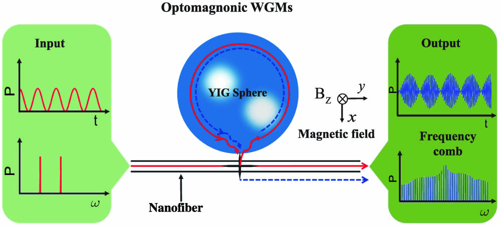
    Fig. 1. Schematic illustration of the optomagnonic WGMs, in which the YIG sphere supports WGMs for photons and the magnetostatic mode for magnons. A magnetic field Bz perpendicular to the plane of the WGM is applied to saturate the magnetization. A bichromatic input laser light (temporal and spectral in the rotating frame) evanescently couples to the optical WGMs via a nanofiber, and the output field supports the generation of optomagnonic frequency combs.
    Time evolution of the TM (TE) mode photon number |a|2 (|b|2) with different optomagnonic coupling strengths g. (a) g=0 and (b) g/2π=2×39.2 Hz for the TM mode; (c) g=0 and (d) g/2π=2×39.2 Hz for the TE mode. The parameters we used are [30,31] ωl/2π=300 THz, ωm/2π=6.75 GHz, [κa,κb,κm]/2π=[15,15,1] MHz, Δa(b)(p)(m)=κm, Pl=10 mW, Pmw=50 mW, and ϵl=ϵp.
    Fig. 2. Time evolution of the TM (TE) mode photon number |a|2 (|b|2) with different optomagnonic coupling strengths g. (a) g=0 and (b) g/2π=2×39.2  Hz for the TM mode; (c) g=0 and (d) g/2π=2×39.2  Hz for the TE mode. The parameters we used are [30,31] ωl/2π=300  THz, ωm/2π=6.75  GHz, [κa,κb,κm]/2π=[15,15,1]  MHz, Δa(b)(p)(m)=κm, Pl=10  mW, Pmw=50  mW, and ϵl=ϵp.
    (a) Frequency spectrum output from the cavity optomagnonic system varies with the optomagnonic coupling strength g/g0 (take g0=2π×39.2 Hz as the normalized value). The color indicates the amplitude of the frequency combs. (b)–(d) Frequency spectra under different optomagnonic coupling strengths g/g0=[0,1,3], respectively. The other parameters are the same as those in Fig. 2.
    Fig. 3. (a) Frequency spectrum output from the cavity optomagnonic system varies with the optomagnonic coupling strength g/g0 (take g0=2π×39.2  Hz as the normalized value). The color indicates the amplitude of the frequency combs. (b)–(d) Frequency spectra under different optomagnonic coupling strengths g/g0=[0,1,3], respectively. The other parameters are the same as those in Fig. 2.
    (a) Dependence of the frequency spectrum on driving power. (b) Number of comb lines as a function of driving power. (c) The complete response of the output spectrum varies with the beat frequency Δp. (d) Frequency spectra at two different beat frequencies Δp/κm=1 (upper panel) and 2 (lower panel). The optomagnonic coupling strength is fixed at g/2π=2×39.2 Hz. The other parameters are the same as those in Fig. 2.
    Fig. 4. (a) Dependence of the frequency spectrum on driving power. (b) Number of comb lines as a function of driving power. (c) The complete response of the output spectrum varies with the beat frequency Δp. (d) Frequency spectra at two different beat frequencies Δp/κm=1 (upper panel) and 2 (lower panel). The optomagnonic coupling strength is fixed at g/2π=2×39.2  Hz. The other parameters are the same as those in Fig. 2.
    Dependence of the frequency spectrum on (a) detuning between the optical driving field and TM mode, (b) detuning between the microwave driving field and magnon mode, (c), (d) decay rates of the TM optical mode and magnon mode, respectively (for convenience, take κm0=2π×1 MHz as the normalized value). The other parameters are the same as those in Fig. 2.
    Fig. 5. Dependence of the frequency spectrum on (a) detuning between the optical driving field and TM mode, (b) detuning between the microwave driving field and magnon mode, (c), (d) decay rates of the TM optical mode and magnon mode, respectively (for convenience, take κm0=2π×1  MHz as the normalized value). The other parameters are the same as those in Fig. 2.
    (a) Effective driving pulse field in time domain. (b) Order and intensity of the optomagnonic frequency comb under different numbers of cycles in a pulse. (c) Frequency comb output from the cavity optomagnonic system under the pulse drive field. (d) Linewidth of the second-order comb tooth. The optomagnonic coupling strength is fixed at g/2π=2×39.2 Hz. The other parameters are the same as those in Fig. 2.
    Fig. 6. (a) Effective driving pulse field in time domain. (b) Order and intensity of the optomagnonic frequency comb under different numbers of cycles in a pulse. (c) Frequency comb output from the cavity optomagnonic system under the pulse drive field. (d) Linewidth of the second-order comb tooth. The optomagnonic coupling strength is fixed at g/2π=2×39.2  Hz. The other parameters are the same as those in Fig. 2.
    Dependences of the intensities of the (a) first, (b) second, (c) third, and (d) fourth comb teeth are shown with different values of ϵp/ϵl. The dashed curves represent the appropriate perturbative scaling law, i.e., S(nω)∝ϵpn, for each frequency tooth. The optomagnonic coupling strength is fixed at g/2π=2×39.2 Hz. The other parameters are the same as those in Fig. 2.
    Fig. 7. Dependences of the intensities of the (a) first, (b) second, (c) third, and (d) fourth comb teeth are shown with different values of ϵp/ϵl. The dashed curves represent the appropriate perturbative scaling law, i.e., S(nω)ϵpn, for each frequency tooth. The optomagnonic coupling strength is fixed at g/2π=2×39.2  Hz. The other parameters are the same as those in Fig. 2.
    Zeng-Xing Liu, Yong-Qing Li. Optomagnonic frequency combs[J]. Photonics Research, 2022, 10(12): 2786
    Download Citation