
Qian Zhao, Shijie Tu, Qiannan Lei, Chengshan Guo, Qiwen Zhan, Yangjian Cai, "Creation of cylindrical vector beams through highly anisotropic scattering media with a single scalar transmission matrix calibration," Photonics Res. 10, 1617 (2022)
- Photonics Research
- Vol. 10, Issue 7, 1617 (2022)
Abstract
1. INTRODUCTION
Optical vector fields may possess singularities associated with the parameterization of elliptical and partial polarization rather than phase [1]. For example, cylindrical vector (CV) beams with cylindrical polarization symmetry contain an undefined polarization azimuth at the center [2,3]. The peculiar polarization symmetry of CV beams gives rise to unique properties under high-numerical-aperture focusing [2,4,5], which has attracted much attention in fields such as superresolution imaging [6,7], optical trapping [8–10], laser materials processing [11], and light–matter interactions [12,13]. Since 1972 [14,15], many methods have been developed to produce CV beams, including using laser intracavity devices [14,15] that force the laser to oscillate in CV modes, polarization manipulation with spatial light modulators (SLMs) [16–18], and employing space variant polarization converters [19–21]. However, all of these studies are typically implemented in free space and experience little or no sample aberrations.
Light propagation in media with inhomogeneous index distributions suffers scattering. In highly anisotropic scattering media (HASM) such as white paint, biological tissue, and multimode fiber, the degrees of freedom of the incident beams including amplitude, phase, and polarization are completely scrambled due to multiple scattering [22–24]. In this case, the applications of CV beams behind the HASM are greatly restrained. To overcome the scattering, wavefront shaping techniques such as iterative optimization [25–27], optical phase conjugation [28,29], and the transmission matrix (TM) method [30–34] have opened the possibility to achieve light control through HASM. For example, an optimized input field obtained by optimizing the intensity of a target focal position enables scattered light propagating along different paths to interfere constructively at the target position, and thus a focus is shaped beyond scattering. A phase conjugation mirror, such as a specially prepared photorefractive crystal, can be used to record the wavefront of the scattered light from a target location in a hologram and then phase conjugate the light back to the target location, therefore generating a focus. Besides, for a scattering medium, the relationship between the input light and the output light can be characterized by a TM. A well-calibrated TM enables the light transporting through the HASM to form the target light field. Moreover, with a trained neural network, deep-learning-based algorithms have shown their great potential in predicting the correct incident field for shaping a desired intensity distribution behind the scattering media [35–37]. Apart from the intensity modulation through scattering media, deep-learning-based algorithms may also be expected to control the polarization degree of freedom beyond scattering.
In a nutshell, the desired light field can be shaped through HASM as long as taking the correct incident wavefront as the input field. However, to obtain the correct incident wavefront for creating CV beams with variant polarization distributions in space through HASM, the existing method [31,34] commonly requires calibration of the vector transmission matrix (VTM) of the HASM that contains four scalar TMs, and inverts it to find the vector input field. Thus this method needing to measure the four scalar TMs and simultaneously manipulate both the spatial and polarization degrees of freedom at the input field consumes much time, needs complex calculations, and relies on a complicated experimental setup.
Sign up for Photonics Research TOC. Get the latest issue of Photonics Research delivered right to you!Sign up now
To address this issue, we present a fast and simple method to construct CV beams through HASM, which only relies on modulation in the spatial degrees of freedom of the scalar input field and calibration of a single scalar TM. Compared to the existing method, our method costs a short time, implements with a simplified optical design, and does not need complex calculations. To shape CV beams through HASM, a radial polarization converter (S-waveplate), which is fabricated by a femtosecond laser writing of self-assembled nanostructures in silica glass [19], and a polarizer are employed in the process of TM calibration. The correct incident wavefront for constructing a CV beam through HASM is obtained by only one single scalar TM calibration. Experimentally, both radially and azimuthally polarized beams are constructed through a ZnO scattering layer. To verify their polarization states, their polarization maps are derived from the first three elements of Stokes parameters. Further, we demonstrate that arbitrarily generalized CV beams can be produced through the ZnO scattering layer by changing the direction of the polarizer. In addition, three arrays of CV beams are generated through the ZnO scattering layer. Our work will promote the applications that rely on CV beams through HASM.
2. PRINCIPLE AND EXPERIMENTAL SETUP
A. Principle of Constructing CV Beams through HASM with a Single Scalar TM Calibration
Figure 1 illustrates the principle of constructing CV beams through HASM with a single scalar TM calibration. As shown in Fig. 1(a), when a linearly polarized beam is incident on a HASM, its state of polarization is scrambled by multiple scattering as well as the amplitude and phase distribution. As a result, the transmitted light is turned into arbitrary intensity speckles with randomly distributed polarization states at the output plane. According to the VTM method, the relationship between the output field
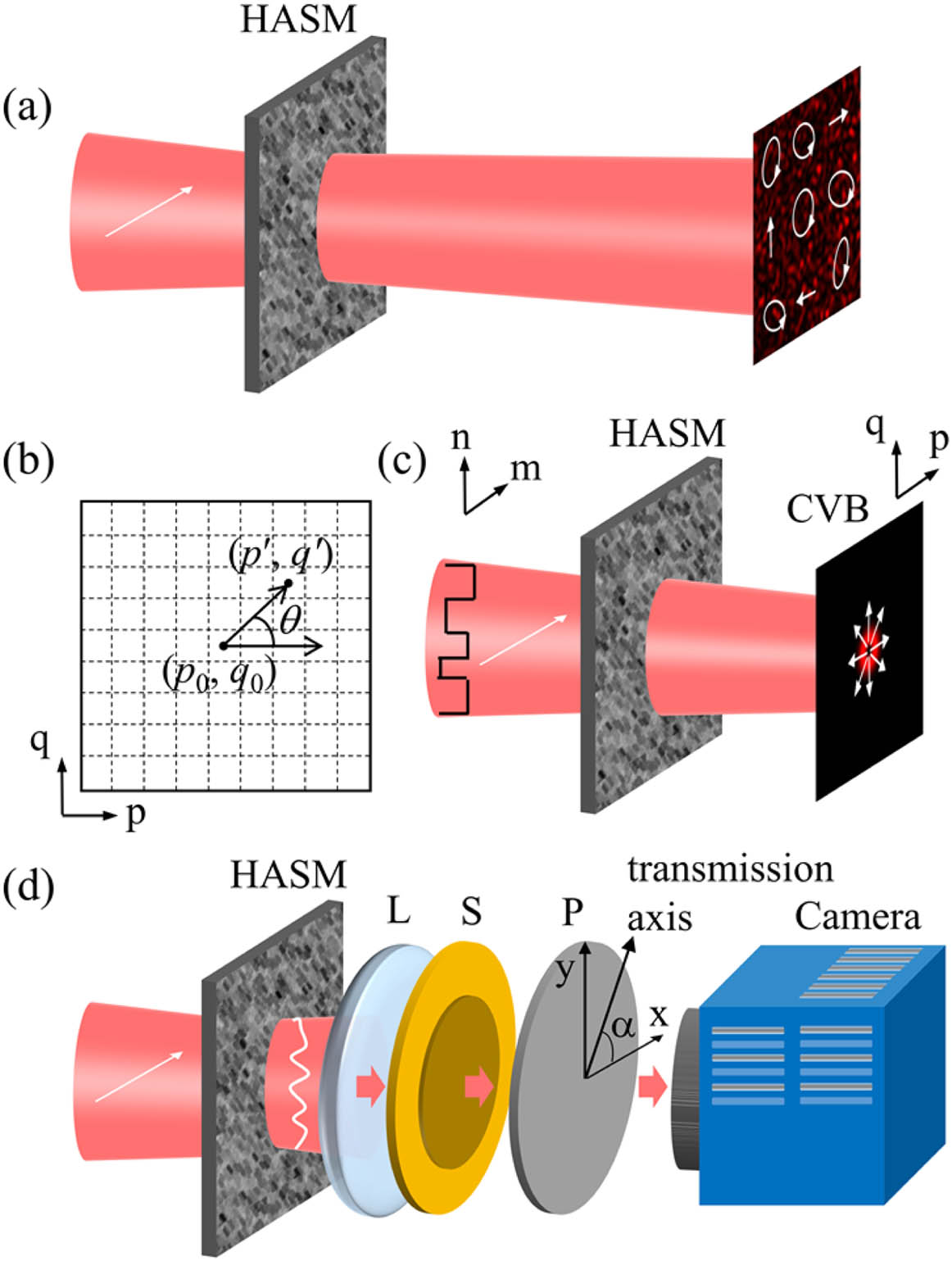
Figure 1.Principle of constructing CV beams through HASM with a single scalar TM calibration. (a) Multiple scattering scrambles the wavefront of the incident linearly polarized beam, and the transmitted light is composed of all spatial modes in different polarization states. (b) Definition of the output coordinates. (c) A CV beam can be produced through HASM with the input field reshaped according to Eq. (
If the input beam is further set to be
In Eqs. (3) and (4), ‘
Each VTM element of a HASM can be considered as a random complex function of both the coordinates
The probability theory shows that the module of
Equation (4) and its approximation Eq. (7) reveal that we can generate a radially polarized beam with its center located at the output mode
Here we further propose a single-step measurement method to determine the two elements of the VTM required for the reshaped input field shown in Eq. (3). Figure 1(d) is the principal schematic of the calibration process, in which a spatially variant half-wave plate (S-waveplate) [40] and a polarizer are used. In the process, the S-waveplate is located at the exit pupil plane of the imaging lens that is employed to magnify and image the transmitted speckle field to the camera plane. In this case, the equivalent effect of the S-waveplate is a spatial polarization filter of the VTM. Thus the field at a position
For example, when
As we can see, the generated output field is a generalized CV beam [5]. Compared to the radially polarized beam, each point of this beam possesses a polarization that is rotated by
B. Experimental Setup
In order to validate our proposal, we built an experimental setup, which is schematically shown in Fig. 2(a). To achieve wavefront shaping, a digital micro-mirror device [27,41,42] (DMD, Vialux V-7001) was employed as the SLM. A laser beam from a laser (
![]()
Figure 2.Experimental scheme. (a) Experimental setup. L, lens; M, mirror; BS, beam splitter; DMD, digital micro-mirror device; F, filter; O, objective; HASM, highly anisotropic scattering medium; S, S-waveplate; P, polarizer; CMOS, complementary metal-oxide-semiconductor camera. (b) Photo of the HASM (a ZnO scattering layer) used. (c), (d) Amplitude and phase distributions of the correct incident field for constructing a radially polarized beam through the HASM. (e) Corresponding binary amplitude mask calculated by Lee method.
To calibrate the TM, a phase shifting method [30] was applied. In the TM calibration, each of the input modes was turned on sequentially with the rest turned off, and the corresponding transmitted speckle field was measured from interferometric measurements where the signal light was introduced with four predetermined phase shifts. By making measurements for all input modes, the corresponding elements of the transmission matrix were calibrated in sequence. In the calibration,
3. RESULTS
A. Construct Radially and Azimuthally Polarized Beams through the ZnO Scattering Layer
We first experimentally constructed a radially and an azimuthally polarized beams through the ZnO scattering layer. To construct a radially polarized beam, the transmission axis of polarizer is set to be parallel with the
![]()
Figure 3.Construct radially polarized and azimuthally polarized beams through the ZnO scattering layer. (a) Intensity pattern of the focus at the plane of CMOS camera when the S-waveplate and polarizer are still located in the optical path. (b) Observed intensity distribution of a radially polarized beam with the S-waveplate and the polarizer removed. (c) Fields after a polarizer whose transmission axis orientation is indicated by the white arrows at 0°, 45°, 90°, and 135°, respectively. (d) Intensity distribution of the radially polarized beam superimposed with the polarization map. The local polarization direction and the local intensity are indicated by the orientation of the lines and the length of lines, respectively. (e)–(h) Corresponding results for creating an azimuthally polarized beam. Scale bar: 20 μm.
B. Construct Generalized CV Beams through the ZnO Scattering Layer
Apart from the radially and azimuthally polarized beams, generalized CV beams possess the particular focusing property [5]. Therefore, in order to promote the applications of generalized CV beams behind HASM, we explored the construction of the generalized CV beams beyond high scattering. Here, four generalized CV beams were produced through the ZnO scattering layer by changing the direction of the polarizer. Note that the angle between the transmission axis of the polarizer and the
![]()
Figure 4.Construct arbitrarily generalized CV beams through the ZnO scattering layer. (a)–(d) Fields after a polarizer whose transmission axis orientation is indicated by the white arrows at 0°, 45°, 90°, and 135°, respectively. For the four generated CV beams,
C. Construct Arrays of CV Beams through the ZnO Scattering Layer
In addition to constructing a single CV beam through the ZnO scattering layer, the arrays of CV beams can be shaped. With the proposed method, a single desired CV beam can be constructed through HASM by impinging the correct incident field for focusing at a predetermined output mode on HASM. To generate multiple CV beams through HASM, correct incident fields
![]()
Figure 5.Construct arrays of CV beams through the ZnO scattering layer. (a) Construct an array of radially polarized beams and the fields after a polarizer whose transmission axis orientation is indicated by the white arrows at 0°, 45°, 90°, and 135°, respectively. (b) Corresponding results of generating an array of azimuthally polarized beams. (c) Corresponding results of producing an array of CV beams with different polarization states. Here, for the four beams located on the upper left, the upper right, the bottom left, and the bottom right in the observation plane,
4. DISCUSSION AND CONCLUSION
We have proposed a simple method to generate CV beams through HASM. For the method of generating CV beams through HASM with VTM calibration [31,34], the target vector output field is defined by the complex field of the desired CV beam; thus the size of the desired CV beam can be user-defined by setting its range in the output coordinates. In comparison, our method does not tailor the size of generated CV beams with such flexibility. The generated field in our method is actually a focus with the form of a CV beam. Its size is proportional to the speckle size of the imaging plane. To alter the size of CV beams, we can change the distance between the HASM and the imaging plane to tune the speckle size at the imaging plane [46]. Besides, the spatial resolution of the generated CV beams is related to the pixel size of the camera, the magnification of the imaging objective O2, and the size of the generated CV beams. Apart from increasing the size of generated CV beam, employing a camera with smaller pixel size or using an imaging objective with larger magnification can help to improve the spatial resolution. In addition, the fidelity of the generated CV beams can be improved by increasing the number of degrees of freedom controlled, i.e.,
In summary, the correct incident wavefront for constructing CV beams through HASM can be obtained by one single scalar transmission matrix calibration in combination with an S-waveplate and a polarizer in the process of TM calibration. Compared with existing methods, the presented method only relies on manipulation of the spatial degrees of freedom of the scalar input field, which is fast and simple in terms of optical implementations and computations. As demonstrations, both radially and azimuthally polarized beams are experimentally constructed through a ZnO scattering layer. Furthermore, generalized CV beams and arrays of CV beams are created after the ZnO scattering layer to further demonstrate the flexibility of this technique. Such a method is expected to promote the applications of CV beams that involve a highly anisotropic scattering environment.
References
[1] M. R. Dennis, K. O’holleran, M. J. Padgett. Singular optics: optical vortices and polarization singularities. Progress in Optics, 53, 293-363(2009).
[2] K. S. Youngworth, T. G. Brown. Focusing of high numerical aperture cylindrical-vector beams. Opt. Express, 7, 77-87(2000).
[3] Q. Zhan. Cylindrical vector beams: from mathematical concepts to applications. Adv. Opt. Photon., 1, 1-57(2009).
[4] R. Dorn, S. Quabis, G. Leuchs. Sharper focus for a radially polarized light beam. Phys. Rev. Lett., 91, 233901(2003).
[5] Q. Zhan, J. R. Leger. Focus shaping using cylindrical vector beams. Opt. Express, 10, 324-331(2002).
[6] Y. Cai, W. Liu, W. Yang, J. Xu, H. Yang, K. Shi. Differential fluorescence microscopy by using a dynamic cylindrical-vector field. Opt. Lett., 46, 2332-2335(2021).
[7] Y. Kozawa, D. Matsunaga, S. Sato. Superresolution imaging via superoscillation focusing of a radially polarized beam. Optica, 5, 86-92(2018).
[8] Q. Zhan. Trapping metallic Rayleigh particles with radial polarization. Opt. Express, 12, 3377-3382(2004).
[9] M.-C. Zhong, L. Gong, D. Li, J.-H. Zhou, Z.-Q. Wang, Y.-M. Li. Optical trapping of core-shell magnetic microparticles by cylindrical vector beams. Appl. Phys. Lett., 105, 181112(2014).
[10] Y. Kozawa, S. Sato. Optical trapping of micrometer-sized dielectric particles by cylindrical vector beams. Opt. Express, 18, 10828-10833(2010).
[11] M. Meier, V. Romano, T. Feurer. Material processing with pulsed radially and azimuthally polarized laser radiation. Appl. Phys. A, 86, 329-334(2007).
[12] L. Zhang, W. Zhang, F. Lu, Z. Yang, T. Xue, M. Liu, C. Meng, P. Li, D. Mao, T. Mei, J. Zhao. Azimuthal vector beam exciting silver triangular nanoprisms for increasing the performance of surface-enhanced Raman spectroscopy. Photon. Res., 7, 1447-1453(2019).
[13] M. Liu, W. Zhang, F. Lu, T. Xue, X. Li, L. Zhang, D. Mao, L. Huang, F. Gao, T. Mei, J. Zhao. Plasmonic tip internally excited via an azimuthal vector beam for surface enhanced Raman spectroscopy. Photon. Res., 7, 526-531(2019).
[14] D. Pohl. Operation of a ruby laser in the purely transverse electric mode TE01. Appl. Phys. Lett., 20, 266-267(1972).
[15] Y. Mushiake, K. Matsumura, N. Nakajima. Generation of radially polarized optical beam mode by laser oscillation. Proc. IEEE, 60, 1107-1109(1972).
[16] X.-L. Wang, J. Ding, W.-J. Ni, C.-S. Guo, H.-T. Wang. Generation of arbitrary vector beams with a spatial light modulator and a common path interferometric arrangement. Opt. Lett., 32, 3549-3551(2007).
[17] W. Han, Y. Yang, W. Cheng, Q. Zhan. Vectorial optical field generator for the creation of arbitrarily complex fields. Opt. Express, 21, 20692-20706(2013).
[18] S. Liu, S. Qi, Y. Zhang, P. Li, D. Wu, L. Han, J. Zhao. Highly efficient generation of arbitrary vector beams with tunable polarization, phase, and amplitude. Photon. Res., 6, 228-233(2018).
[19] M. Beresna, M. Gecevičius, P. G. Kazansky. Polarization sensitive elements fabricated by femtosecond laser nanostructuring of glass [Invited]. Opt. Mater. Express, 1, 783-795(2011).
[20] M. Beresna, M. Gecevičius, P. G. Kazansky, T. Gertus. Radially polarized optical vortex converter created by femtosecond laser nanostructuring of glass. Appl. Phys. Lett., 98, 201101(2011).
[21] C. Hernández-García, A. Turpin, J. San Román, A. Picón, R. Drevinskas, A. Cerkauskaite, P. G. Kazansky, C. G. Durfee, Í. J. Sola. Extreme ultraviolet vector beams driven by infrared lasers. Optica, 4, 520-526(2017).
[22] M. Plöschner, T. Tyc, T. Čižmár. Seeing through chaos in multimode fibres. Nat. Photonics, 9, 529-535(2015).
[23] W. Xiong, C. W. Hsu, Y. Bromberg, J. E. Antonio-Lopez, R. Amezcua Correa, H. Cao. Complete polarization control in multimode fibers with polarization and mode coupling. Light Sci. Appl., 7, 54(2018).
[24] H. B. d. Aguiar, S. Gigan, S. Brasselet. Polarization recovery through scattering media. Sci. Adv., 3, e1600743(2017).
[25] I. M. Vellekoop. Feedback-based wavefront shaping. Opt. Express, 23, 12189-12206(2015).
[26] D. B. Conkey, A. N. Brown, A. M. Caravaca-Aguirre, R. Piestun. Genetic algorithm optimization for focusing through turbid media in noisy environments. Opt. Express, 20, 4840-4849(2012).
[27] H. Li, C. M. Woo, T. Zhong, Z. Yu, Y. Luo, Y. Zheng, X. Yang, H. Hui, P. Lai. Adaptive optical focusing through perturbed scattering media with a dynamic mutation algorithm. Photon. Res., 9, 202-212(2021).
[28] Z. Yaqoob, D. Psaltis, M. S. Feld, C. Yang. Optical phase conjugation for turbidity suppression in biological samples. Nat. Photonics, 2, 110-115(2008).
[29] Y. Liu, P. Lai, C. Ma, X. Xu, A. A. Grabar, L. V. Wang. Optical focusing deep inside dynamic scattering media with near-infrared time-reversed ultrasonically encoded (TRUE) light. Nat. Commun., 6, 5904(2015).
[30] S. Popoff, G. Lerosey, R. Carminati, M. Fink, A. Boccara, S. Gigan. Measuring the transmission matrix in optics: an approach to the study and control of light propagation in disordered media. Phys. Rev. Lett., 104, 100601(2010).
[31] Y.-Y. Xie, B.-Y. Wang, Z.-J. Cheng, Q.-Y. Yue, C.-S. Guo. Measurement of vector transmission matrix and control of beam focusing through a multiple-scattering medium based on a vector spatial light modulator and two-channel polarization holography. Appl. Phys. Lett., 110, 221105(2017).
[32] S.-J. Tu, X. Zhao, Q.-Y. Yue, Y.-J. Cai, C.-S. Guo, Q. Zhao. Shaping the illumination beams for STED imaging through highly scattering media. Appl. Phys. Lett., 119, 211105(2021).
[33] S. Tripathi, R. Paxman, T. Bifano, K. C. Toussaint. Vector transmission matrix for the polarization behavior of light propagation in highly scattering media. Opt. Express, 20, 16067-16076(2012).
[34] P. Yu, Q. Zhao, X. Hu, Y. Li, L. Gong. Tailoring arbitrary polarization states of light through scattering media. Appl. Phys. Lett., 113, 121102(2018).
[35] A. Turpin, I. Vishniakou, J. d. Seelig. Light scattering control in transmission and reflection with neural networks. Opt. Express, 26, 30911-30929(2018).
[36] Y. Luo, S. Yan, H. Li, P. Lai, Y. Zheng. Towards smart optical focusing: deep learning-empowered dynamic wavefront shaping through nonstationary scattering media. Photon. Res., 9, B262-B278(2021).
[37] Y. Luo, S. Yan, H. Li, P. Lai, Y. Zheng. Focusing light through scattering media by reinforced hybrid algorithms. APL Photon., 5, 016109(2020).
[38] S. Tripathi, K. C. Toussaint. Harnessing randomness to control the polarization of light transmitted through highly scattering media. Opt. Express, 22, 4412-4422(2014).
[39] I. M. Vellekoop, A. Mosk. Focusing coherent light through opaque strongly scattering media. Opt. Lett., 32, 2309-2311(2007).
[40] L. Gong, Y. Ren, W. Liu, M. Wang, M. Zhong, Z. Wang, Y. Li. Generation of cylindrically polarized vector vortex beams with digital micromirror device. J. Appl. Phys., 116, 183105(2014).
[41] J. Yang, Q. He, L. Liu, Y. Qu, R. Shao, B. Song, Y. Zhao. Anti-scattering light focusing by fast wavefront shaping based on multi-pixel encoded digital-micromirror device. Light Sci. Appl., 10, 149(2021).
[42] D. Wang, E. H. Zhou, J. Brake, H. Ruan, M. Jang, C. Yang. Focusing through dynamic tissue with millisecond digital optical phase conjugation. Optica, 2, 728-735(2015).
[43] W.-H. Lee. Binary computer-generated holograms. Appl. Opt., 18, 3661-3669(1979).
[44] B. Perez-Garcia, C. López-Mariscal, R. I. Hernandez-Aranda, J. C. Gutiérrez-Vega. On-demand tailored vector beams. Appl. Opt., 56, 6967-6972(2017).
[45] S. Popoff, G. Lerosey, M. Fink, A. C. Boccara, S. Gigan. Image transmission through an opaque material. Nat. Commun., 1, 81(2010).
[46] E. Edrei, G. Scarcelli. A trade-off between speckle size and intensity enhancement of a focal point behind a scattering layer. Sci. Rep., 9, 11256(2019).
[47] J.-H. Park, C. Park, H. Yu, Y.-H. Cho, Y. Park. Dynamic active wave plate using random nanoparticles. Opt. Express, 20, 17010-17016(2012).


Set citation alerts for the article
Please enter your email address

© Copyright 2018-2021 | Chinese Laser Press. All Rights Reserved 沪ICP备15018463号-20