• Photonics Research
  • Vol. 10, Issue 7, 1617 (2022)
Qian Zhao1, Shijie Tu1, Qiannan Lei1, Chengshan Guo1、4、*, Qiwen Zhan2、5、*, and Yangjian Cai1、3、6、*
Author Affiliations
  • 1Shandong Provincial Engineering and Technical Center of Light Manipulations & Shandong Provincial Key Laboratory of Optics and Photonic Device, School of Physics and Electronics, Shandong Normal University, Jinan 250358, China
  • 2School of Optical-Electrical and Computer Engineering, University of Shanghai for Science and Technology, Shanghai 200093, China
  • 3School of Physical Science and Technology, Soochow University, Suzhou 215006, China
  • 4e-mail: guochsh@sdnu.edu.cn
  • 5e-mail: qwzhan@usst.edu.cn
  • 6e-mail: yangjiancai@sdnu.edu.cn
  • show less
    DOI: 10.1364/PRJ.457928 Cite this Article Set citation alerts
    Qian Zhao, Shijie Tu, Qiannan Lei, Chengshan Guo, Qiwen Zhan, Yangjian Cai. Creation of cylindrical vector beams through highly anisotropic scattering media with a single scalar transmission matrix calibration[J]. Photonics Research, 2022, 10(7): 1617 Copy Citation Text show less
    Principle of constructing CV beams through HASM with a single scalar TM calibration. (a) Multiple scattering scrambles the wavefront of the incident linearly polarized beam, and the transmitted light is composed of all spatial modes in different polarization states. (b) Definition of the output coordinates. (c) A CV beam can be produced through HASM with the input field reshaped according to Eq. (3). (d) Principal schematic of TM calibration to shape CV beams through HASM with a single scalar TM calibration. HASM, highly anisotropic scattering medium; L, lens; S, S-waveplate; P, polarizer; CVB, cylindrical vector beam.
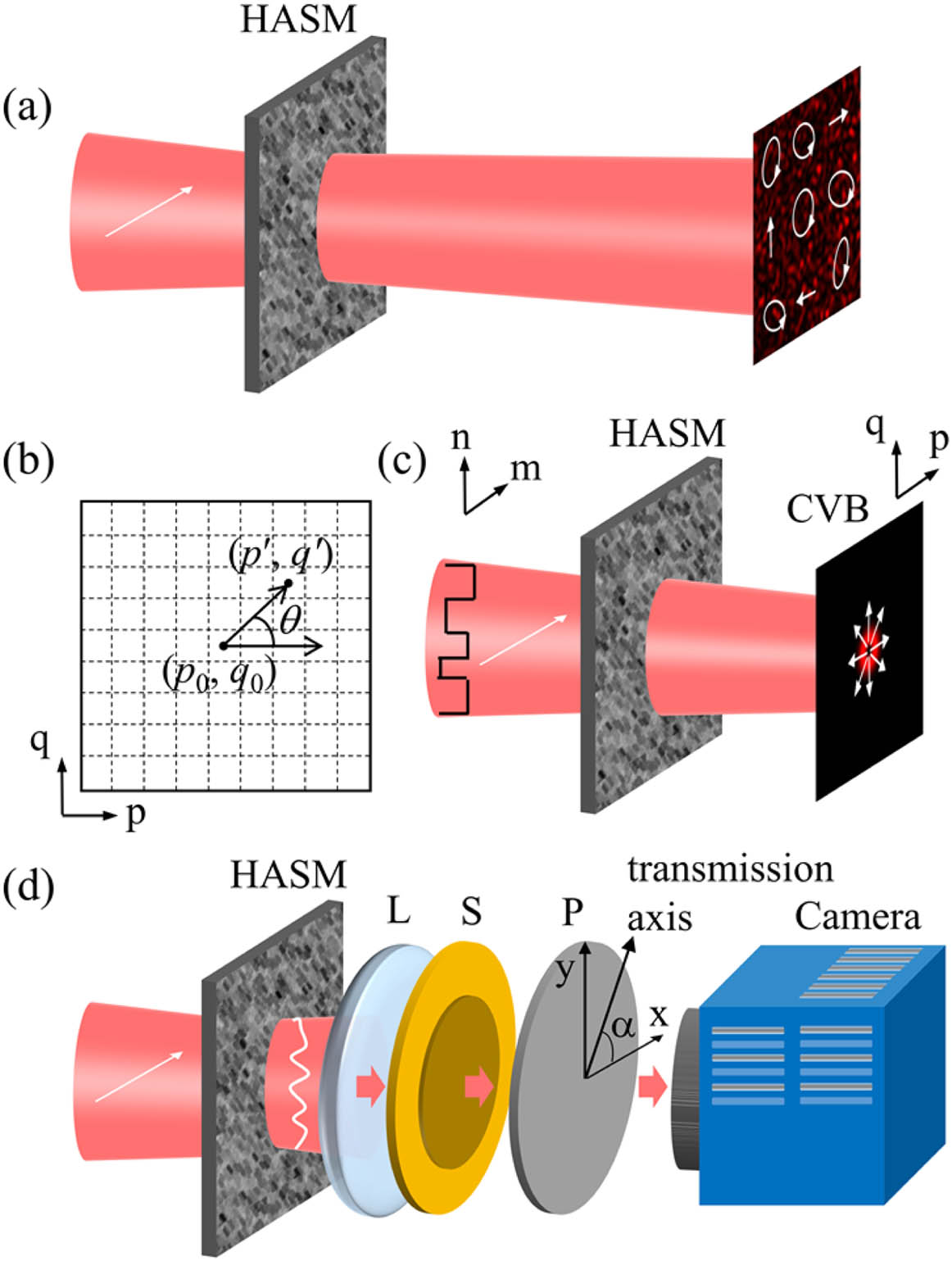
    Fig. 1. Principle of constructing CV beams through HASM with a single scalar TM calibration. (a) Multiple scattering scrambles the wavefront of the incident linearly polarized beam, and the transmitted light is composed of all spatial modes in different polarization states. (b) Definition of the output coordinates. (c) A CV beam can be produced through HASM with the input field reshaped according to Eq. (3). (d) Principal schematic of TM calibration to shape CV beams through HASM with a single scalar TM calibration. HASM, highly anisotropic scattering medium; L, lens; S, S-waveplate; P, polarizer; CVB, cylindrical vector beam.
    Experimental scheme. (a) Experimental setup. L, lens; M, mirror; BS, beam splitter; DMD, digital micro-mirror device; F, filter; O, objective; HASM, highly anisotropic scattering medium; S, S-waveplate; P, polarizer; CMOS, complementary metal-oxide-semiconductor camera. (b) Photo of the HASM (a ZnO scattering layer) used. (c), (d) Amplitude and phase distributions of the correct incident field for constructing a radially polarized beam through the HASM. (e) Corresponding binary amplitude mask calculated by Lee method.
    Fig. 2. Experimental scheme. (a) Experimental setup. L, lens; M, mirror; BS, beam splitter; DMD, digital micro-mirror device; F, filter; O, objective; HASM, highly anisotropic scattering medium; S, S-waveplate; P, polarizer; CMOS, complementary metal-oxide-semiconductor camera. (b) Photo of the HASM (a ZnO scattering layer) used. (c), (d) Amplitude and phase distributions of the correct incident field for constructing a radially polarized beam through the HASM. (e) Corresponding binary amplitude mask calculated by Lee method.
    Construct radially polarized and azimuthally polarized beams through the ZnO scattering layer. (a) Intensity pattern of the focus at the plane of CMOS camera when the S-waveplate and polarizer are still located in the optical path. (b) Observed intensity distribution of a radially polarized beam with the S-waveplate and the polarizer removed. (c) Fields after a polarizer whose transmission axis orientation is indicated by the white arrows at 0°, 45°, 90°, and 135°, respectively. (d) Intensity distribution of the radially polarized beam superimposed with the polarization map. The local polarization direction and the local intensity are indicated by the orientation of the lines and the length of lines, respectively. (e)–(h) Corresponding results for creating an azimuthally polarized beam. Scale bar: 20 μm.
    Fig. 3. Construct radially polarized and azimuthally polarized beams through the ZnO scattering layer. (a) Intensity pattern of the focus at the plane of CMOS camera when the S-waveplate and polarizer are still located in the optical path. (b) Observed intensity distribution of a radially polarized beam with the S-waveplate and the polarizer removed. (c) Fields after a polarizer whose transmission axis orientation is indicated by the white arrows at 0°, 45°, 90°, and 135°, respectively. (d) Intensity distribution of the radially polarized beam superimposed with the polarization map. The local polarization direction and the local intensity are indicated by the orientation of the lines and the length of lines, respectively. (e)–(h) Corresponding results for creating an azimuthally polarized beam. Scale bar: 20 μm.
    Construct arbitrarily generalized CV beams through the ZnO scattering layer. (a)–(d) Fields after a polarizer whose transmission axis orientation is indicated by the white arrows at 0°, 45°, 90°, and 135°, respectively. For the four generated CV beams, α=π/8, π/4, 3π/4, and 7π/8, respectively. (a′)–(d′) The intensity distribution of the generated CV beams superimposed with their polarization maps. Scale bar: 20 μm.
    Fig. 4. Construct arbitrarily generalized CV beams through the ZnO scattering layer. (a)–(d) Fields after a polarizer whose transmission axis orientation is indicated by the white arrows at 0°, 45°, 90°, and 135°, respectively. For the four generated CV beams, α=π/8, π/4, 3π/4, and 7π/8, respectively. (a′)–(d′) The intensity distribution of the generated CV beams superimposed with their polarization maps. Scale bar: 20 μm.
    Construct arrays of CV beams through the ZnO scattering layer. (a) Construct an array of radially polarized beams and the fields after a polarizer whose transmission axis orientation is indicated by the white arrows at 0°, 45°, 90°, and 135°, respectively. (b) Corresponding results of generating an array of azimuthally polarized beams. (c) Corresponding results of producing an array of CV beams with different polarization states. Here, for the four beams located on the upper left, the upper right, the bottom left, and the bottom right in the observation plane, α was respectively set as 0, 3π/4, π/4, and π/2. Scale bar: 100 μm.
    Fig. 5. Construct arrays of CV beams through the ZnO scattering layer. (a) Construct an array of radially polarized beams and the fields after a polarizer whose transmission axis orientation is indicated by the white arrows at 0°, 45°, 90°, and 135°, respectively. (b) Corresponding results of generating an array of azimuthally polarized beams. (c) Corresponding results of producing an array of CV beams with different polarization states. Here, for the four beams located on the upper left, the upper right, the bottom left, and the bottom right in the observation plane, α was respectively set as 0, 3π/4, π/4, and π/2. Scale bar: 100 μm.
    Qian Zhao, Shijie Tu, Qiannan Lei, Chengshan Guo, Qiwen Zhan, Yangjian Cai. Creation of cylindrical vector beams through highly anisotropic scattering media with a single scalar transmission matrix calibration[J]. Photonics Research, 2022, 10(7): 1617
    Download Citation