
Fengya Lu, Lei Gong, Yan Kuai, Xi Tang, Yifeng Xiang, Pei Wang, Douguo Zhang, "Controllable optofluidic assembly of biological cells using an all-dielectric one-dimensional photonic crystal," Photonics Res. 10, 14 (2022)
- Photonics Research
- Vol. 10, Issue 1, 14 (2022)
Abstract
1. INTRODUCTION
Manipulating biological cells and nanoparticles is of paramount importance in biomedical studies such as cell interaction, cell adhesion, cell rheology, metastasis of circulating tumor cells, single cell transfection, and tissue engineering [1–4]. Optical tweezers have proven to be a powerful tool for trapping and manipulating biological particles [5–9]. However, conventional optical tweezers trap tiny objects using optical gradient forces near a tightly focused laser beam [10–12], which has a limitation in long-range transportation and manipulation of target objects and cannot manipulate many biological objects [13]. Various types of novel tweezers have been developed to address this limitation of conventional optical tweezers [14,15]. For example, a strategy of combining the advantages of optical and plasmonic tweezers is proposed to achieve dynamic manipulation and long-range delivery of target objects [16–19]. Electrothermoplasmonic tweezers can transport particles over a long distance and trap them at the plasmonic structures [13,20,21]. Recently, opto-thermophoretic tweezers have emerged as powerful tools for long-range optical manipulation [22–24]. Opto-thermophoretic manipulation exploits the thermophoretic migration of particles and colloidal species under a light-controlled temperature gradient field [25–27]. The thermophoretic pumping forces of opto-thermophoretic tweezers are beyond the action range of direct optical gradient forces, allowing long-range manipulation. Thus, opto-thermophoretic manipulation provides an effective strategy for assembly of many cells. Active assembly of cells could help gain insights in tissue development and diseases [28–30], which always involves manipulation of many cells [31].
In this paper, we demonstrate a new opto-thermophoretic tweezer based on an all-dielectric one-dimensional photonic crystal (1DPC) platform for controllable assembly of many biological cells. Different from the metallic substrates adopted in conventional thermophoretic tweezers, the all-dielectric 1DPC can provide a stronger temperature gradient for thermophoretic manipulation due to the excitation of the Bloch surface waves (BSWs). BSWs are electromagnetic surface waves excited at the interface between a truncated periodic dielectric multilayer with a photonic band gap (PBG) and its surrounding medium [32,33]. Until now, BSWs have been applied in nanoscale optical circuits [34,35], fluorescence emission enhancement or sorting [36], enhanced Goos–Hanchen shift [37], and strong polariton-polariton nonlinearities of 2D materials [38]. However, to the best of our knowledge, there is no report on how to use the thermal and optical forces induced by the BSWs of 1DPC to trap and assemble many biological cells. The proposed opto-thermophoretic tweezer allows reversible assembly of biological cells by the thermophoresis and long-ranged optofluidic pumping force, due to the excitation of the BSWs on the 1DPC. Focused BSWs also allow us to stably trap a single particle by the short-ranged optical gradient force, which can serve as the initial origin for the reversible cellular assembly. Then the proposed thermophoretic tweezer can take the advantages of both optical and thermophoretic manipulation simultaneously.
2. METHODS AND EXPERIMENTS
A. Structure of 1DPC and Its Property
The opto-thermophoretic tweezer is constructed based on an all-dielectric 1DPC. The sketch of the 1DPC geometry is illustrated in Fig. 1(a), which is a dielectric multilayer nanostructure with a well-designed PBG. The dielectric multilayer is composed of
Sign up for Photonics Research TOC. Get the latest issue of Photonics Research delivered right to you!Sign up now
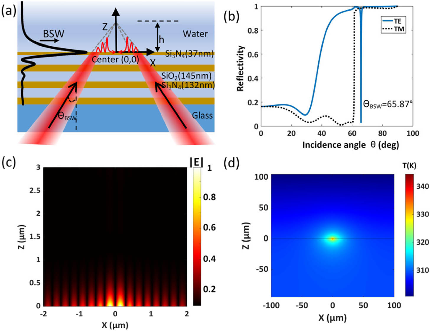
Figure 1.Schematic of the 1DPC and its property. (a) Schematic diagram of the 1DPC.
Due to the absorption characteristics and low thermal conductivity of the dielectric multilayer, the virtual optical probe will induce a localized spot heat source at the water–1DPC interface. A stable-state temperature distribution can be obtained when the heat diffusion between the heated 1DPC and the water environment achieves a balance. Quantitatively, we simulated the temperature distribution of the region near the interface by using the finite element method (FEM) [41]. The thickness of the water film is set to be 200 μm, and the initial temperature of the surrounding environment is set to be 293.15 K. The laser power is 60 mW, and the defocused height is set to be 5 μm above the 1DPC–water interface. All these parameters are consistent with the experimental ones that will be detailed below. Figure 1(d) presents the calculated temperature profiles on the incident
B. Principle of Optofluidic Assembly of Biological Cells
Opto-thermophoretic tweezers manipulate particles by a laser-generated temperature gradient field in the fluids. The thermal gradient drives the particles to move toward the cold or the hot regions. This phenomenon is termed as thermophoresis or the Soret effect, and the driving force is thus called as the thermophoretic force [42,43]. Theoretically, the drift velocity of objects is linear with the temperature gradient
![]()
Figure 2.Working principle of cell assembly with the optofluidic manipulation. (a) Thermophoretic trapping of biological cells in fluidics. Water molecules form an electric double layer on the surface of the negatively charged cells. Under the action of thermophoresis, the biological cells with negative Soret coefficients will move to the hot regions and finally be trapped at the hot spot. The red arrow indicates the movement direction of cells. (b) Simulated maps of temperature gradient along the radial (
Considering the thermophilic nature of biological cells, we further analyze the optofluidic force for cells under the temperature field. For this purpose, the temperature gradient is calculated based on the temperature field of the 1DPC in Fig. 1(d). Figure 2(b) shows the calculated temperature gradient distributions along radial (
Furthermore, the all-dielectric 1DPC substrate can be adopted to generate focused BSWs, which can stably trap a single particle due to the short-ranged optical gradient force [18]. In this manner, our proposed scheme allows combining the advantages of optical and thermophoretic manipulation. For instance, the optical force of focused BSWs could capture a single particle to serve as a controllable origin of the assembly. Thus, the 1DPC-based tweezers enable versatile trapping and manipulation by long-ranged and short-ranged forces simultaneously. For the cellular assembly, a schematic diagram that illustrates the main actions in the optofluidic manipulation is presented in Fig. 2(d), including the flow-induced force (arrows in yellow), the optical force associated with the focused BSWs (illustrated by a focused beam), and thermophoresis (arrows in red) caused by temperature gradient.
C. Experimental Setup of the Opto-Thermophoretic Tweezer
The opto-thermophoretic tweezer is constructed based on an inverted microscope, which contains a BSW excitation scheme and the 1DPC sample as shown in Fig. 3. A laser with an emission power of 60 mW working at the wavelength of 671 nm serves as the excitation source. The polarization of BSW is TE for our 1DPC structure. To improve the excitation efficiency, a ring-shaped laser beam generated by a pair of axicons is adopted. The shaped laser beam passes through a linear polarizer and a vortex retarder to generate an azimuthally polarized beam. An oil immersion objective (numerical aperture,
![]()
Figure 3.Schematic diagram of the experimental setup. The pair of axicons can generate a ring-shaped laser beam; besides, the polarizer and vertex retarder are used to generate an annular azimuthally polarized beam. The inset graph shows the BFP image of the laser beam reflected from the 1DPC shot by CCD1, in which the dark ring (labeled
3. RESULTS AND DISCUSSIONS
A. Optical and Thermophoretic Manipulation
To prove the ability of our 1DPC-based opto-thermophoretic tweezer, we performed a set of experiments to demonstrate the optical and thermophoretic manipulation. We first demonstrate the long-ranged and attractive character of the flow-induced pumping force. For this purpose, 5 μm polystyrene (PS) beads are dispersed in water, and their movements are recorded after the laser is turned on. Figure 4(a) shows some frames of their behavior, and
![]()
Figure 4.Optical and thermophoretic manipulation of colloid particles and yeast cells. (a) The uncaptured particles (yellow circle) are convected away from the interface by the optofluidic flow. (b) In contrast to the colloid particles (yellow circle), yeast cells are trapped (
In addition, we investigated the role of the thermophoresis using a mixed solution of PS particles and yeast cells. The result is shown in Fig. 4(b). As expected, both the PS beads and the yeast cells are pumped toward the center by thermal convection flow, but then they show totally different behaviors near the focus. The PS beads (yellow circle) are pushed away from the surface, while the yeast cells are trapped (
Finally, we analyzed the function of the optical gradient forces in the manipulation. In the above experiments, we find that once a particle migrates toward the focus, the short-ranged optical gradient force associated with the focused BSWs can trap it. Different from the thermophoresis force, the optical gradient force could trap both the yeast cell and the PS bead. Even if we moved the substrate quickly, the particle could be stably trapped. As shown in Fig. 4(c), the trapped particle (red circle) does not move with the substrate, but the uncaptured yeast cells (labelled by yellow circles) do. Once the substrate stops, the yeast cells assemble around the trapped particle immediately under the action of the thermal convection flow and thermophoresis. The whole manipulation process is shown in
B. Reversible Assembly of Yeast Cells
By exploiting the ability of optical and thermophoretic manipulation, we achieve controllable assembly of many yeast cells. Figure 5(a) shows the crystallization process of the trapped yeast cells. Without the laser illumination (
![]()
Figure 5.Reversible assembly of yeast cells. (a) Time-sequenced set of the cell assembly under the irradiation of 60 mW laser power at 671 nm. At
To further characterize the cellular assembly, we analyzed the number of trapped cells as a function of illumination time. As depicted in Fig. 5(c), the number of trapped cells increases exponentially at the beginning and becomes saturated finally. If the illumination time is long enough, the yeast cells throughout the entire field of view can form a crystallization as shown in Fig. 6(a). Due to the yeast cells being deformable and not uniform in size, at the central region, the soft cells are deformed in response to the surrounding stresses, distinguished from the point to point contact among rigid spheres [44]. The mechanical forces were transmitted among individual cells via cell–cell contact, and thus the cells were squeezed into polygon crystallization. Besides, this shape deformation might be involved in cell–cell adhesions. Figure 6(b) shows the outlines of the deformed cells. It is noted that the edge number of the polygon varies with the size of the cell, ranging from 4 to 8. This kind of cell crystallization is similar to the real morphology of tissues, such as epithelial tissue [29,30]. Thus, our method provides a way to mimic the structure in tissues.
![]()
Figure 6.Crystallization of yeast cells. (a) Image of the optofluidic crystallization of yeast cells. The cells are squeezed into polygons due to their deformability. The scale bar is 10 μm. (b) Outlines of the deformed cells. The edge numbers of the polygons are labeled.
To verify that the optothermal assembly relies on the excitation of the BSWs, we tested the assembly using excited laser beam with different angles of incidence. Figure 7(a) illustrates the setup with a single-direction illumination [45], where the BSWs were excited by a laser beam with TE polarization on the 1DPC at a given angle of incidence. First, we set the angle of incidence fixed at
![]()
Figure 7.Angular dependence of the cell assembly. (a) Schematic of the incident angle. (b) Assembly process of yeast cells at
C. Trapping and Assembly of
Apart from the yeast cells, we tried to trap and assemble the
![]()
Figure 8.Trapping and assembly of
4. CONCLUSIONS
We have proposed a new opto-thermophoretic tweezer based on an all-dielectric 1DPC and applied it for controllable assembly of biological cells. Different from the metallic substrates used in conventional opto-thermophoretic tweezers, the all-dielectric 1DPC provides lower temperatures but higher temperature gradients in the fluids, which is beneficial for low-power optofluidic manipulation. This all-dielectric 1DPC is much more stable than the metallic thin film and can be used for many times in experiments. It is well known in cell biology that the techniques used to culture cells on dielectric substrates are more mature and generally applicable than those for growth on metal films. The 1DPC-based tweezer enables the combination of the long-ranged flow-induced force, local thermophoresis force and short-ranged optical force that is associated with focused BSWs. By exploiting the capacity of both optical and thermophoretic manipulation, we demonstrated controllable assembly of many yeast cells as well as
Acknowledgment
Acknowledgment. D. Zhang is supported by a USTC Tang Scholarship. We acknowledge support from the University of Science and Technology of China's Center for Micro and Nanoscale Research and Fabrication.
References
[1] P. Jing, Y. Liu, E. G. Keeler, N. M. Cruz, B. S. Freedman, L. Y. Lin. Optical tweezers system for live stem cell organization at the single-cell level. Biomed. Opt. Express, 9, 771-779(2018).
[2] M. Waleed, S. U. Hwang, J. D. Kim, I. Shabbir, S. M. Shin, Y. G. Lee. Single-cell optoporation and transfection using femtosecond laser and optical tweezers. Biomed. Opt. Express, 4, 1533-1547(2013).
[3] K. Berghoff, W. Gross, M. Eisentraut, H. Kress. Using blinking optical tweezers to study cell rheology during initial cell-particle contact. Biophys. J., 120, 3527-3537(2021).
[4] V. M. Freitas, G. Hilfenhaus, M. L. Iruela-Arispe. Metastasis of circulating tumor cells: speed matters. Dev. Cell, 45, 3-5(2018).
[5] Q. Zhao, H. W. Wang, P. P. Yu, S. H. Zhang, J. H. Zhou, Y. M. Li, L. Gong. Trapping and manipulation of single cells in crowded environments. Front Bioeng. Biotechnol., 8, 422(2020).
[6] A. Ashkin, J. M. Dziedzic, T. Yamane. Optical trapping and manipulation of single cells using infrared-laser beams. Nature, 330, 769-771(1987).
[7] A. H. J. Yang, S. D. Moore, B. S. Schmidt, M. Klug, M. Lipson, D. Erickson. Optical manipulation of nanoparticles and biomolecules in sub-wavelength slot waveguides. Nature, 457, 71-75(2009).
[8] M. C. Zhong, X. B. Wei, J. H. Zhou, Z. Q. Wang, Y. M. Li. Trapping red blood cells in living animals using optical tweezers. Nat. Commun., 4, 1768(2013).
[9] M. C. Zhong, L. Gong, J. H. Zhou, Z. Q. Wang, Y. M. Li. Optical trapping of red blood cells in living animals with a water immersion objective. Opt. Lett., 38, 5134-5137(2013).
[10] A. Ashkin, J. M. Dziedzic, J. E. Bjorkholm, S. Chu. Observation of a single-beam gradient force optical trap for dielectric particles. Opt. Lett., 11, 288-290(1986).
[11] D. G. Grier. A revolution in optical manipulation. Nature, 424, 810-816(2003).
[12] Y. J. Yang, Y. X. Ren, M. Z. Chen, Y. Arita, C. Rosales-Guzman. Optical trapping with structured light: a review. Adv. Photon., 3, 034001(2021).
[13] J. C. Ndukaife, A. V. Kildishev, A. G. Nnanna, V. M. Shalaev, S. T. Wereley, A. Boltasseva. Long-range and rapid transport of individual nano-objects by a hybrid electrothermoplasmonic nanotweezer. Nat. Nanotechnol., 11, 53-59(2016).
[14] V. Sharma, D. Paul, S. K. Chaubey, S. Tiwari, G. V. P. Kumar. Large-scale optothermal assembly of colloids mediated by a gold microplate. J. Phys. Condens. Matter, 32, 324002(2020).
[15] P. P. Patra, R. Chikkaraddy, R. P. N. Tripathi, A. Dasgupta, G. V. P. Kumar. Plasmofluidic single-molecule surface-enhanced Raman scattering from dynamic assembly of plasmonic nanoparticles. Nat. Commun., 5, 4357(2014).
[16] W. Ding, T. Zhu, L.-M. Zhou, C.-W. Qiu. Photonic tractor beams: a review. Adv. Photon., 1, 024001(2019).
[17] Y. Q. Zhang, X. J. Dou, Y. M. Dai, X. Y. Wang, C. J. Min, X. C. Yuan. All-optical manipulation of micrometer-sized metallic particles. Photon. Res., 6, 66-71(2018).
[18] Y. Zhang, C. Min, X. Dou, X. Wang, H. P. Urbach, M. G. Somekh, X. Yuan. Plasmonic tweezers: for nanoscale optical trapping and beyond. Light Sci. Appl., 10, 59(2021).
[19] M. L. Juan, M. Righini, R. Quidant. Plasmon nano-optical tweezers. Nat. Photonics, 5, 349-356(2011).
[20] Z.-S. Li, T.-W. Lu, P.-R. Huang, P.-T. Lee. Efficient nano-tweezers via a silver plasmonic bowtie notch with curved grooves. Photon. Res., 9, 281-288(2021).
[21] C. Hong, S. Yang, J. C. Ndukaife. Stand-off trapping and manipulation of sub-10 nm objects and biomolecules using opto-thermo-electrohydrodynamic tweezers. Nat. Nanotechnol., 15, 908-913(2020).
[22] L. Lin, X. Peng, X. Wei, Z. Mao, C. Xie, Y. Zheng. Thermophoretic tweezers for low-power and versatile manipulation of biological cells. ACS Nano, 11, 3147-3154(2017).
[23] D. Niether, S. Wiegand. Thermophoresis of biological and biocompatible compounds in aqueous solution. J. Phys. Condens. Matter, 31, 503003(2019).
[24] S. Liu, L. Lin, H. B. Sun. Opto-thermophoretic manipulation. ACS Nano, 15, 5925-5943(2021).
[25] M. Braun, A. P. Bregulla, K. Gunther, M. Mertig, F. Cichos. Single molecules trapped by dynamic inhomogeneous temperature fields. Nano Lett., 15, 5499-5505(2015).
[26] M. Braun, F. Cichos. Optically controlled thermophoretic trapping of single nano-objects. ACS Nano, 7, 11200-11208(2013).
[27] F. M. Weinert, D. Braun. Observation of slip flow in thermophoresis. Phys. Rev. Lett., 101, 168301(2008).
[28] J. A. Park, L. Atia, J. A. Mitchel, J. J. Fredberg, J. P. Butler. Collective migration and cell jamming in asthma, cancer and development. J. Cell Sci., 129, 3375-3383(2016).
[29] C. P. Heisenberg, Y. Bellaiche. Forces in tissue morphogenesis and patterning. Cell, 153, 948-962(2013).
[30] C. Guillot, T. Lecuit. Mechanics of epithelial tissue homeostasis and morphogenesis. Science, 340, 1185-1189(2013).
[31] G. Makey, S. Galioglu, R. Ghaffari, E. D. Engin, G. Yıldırım, Ö. Yavuz, O. Bektaş, Ü. S. Nizam, Ö. Akbulut, Ö. Şahin, K. Güngör, D. Dede, H. V. Demir, F. Ö. Ilday, S. Ilday. Universality of dissipative self-assembly from quantum dots to human cells. Nat. Phys., 16, 795-801(2020).
[32] P. Yeh, A. Yariv, C. S. Hong. Electromagnetic propagation in periodic stratified media. 1. General theory. J. Opt. Soc. Am., 67, 423-438(1977).
[33] L. Yu, E. Barakat, T. Sfez, L. Hvozdara, J. Di Francesco, H. P. Herzig. Manipulating Bloch surface waves in 2D: a platform concept-based flat lens. Light Sci. Appl., 3, e124(2014).
[34] E. Descrovi, T. Sfez, M. Quaglio, D. Brunazzo, L. Dominici, F. Michelotti, H. P. Herzig, O. J. F. Martin, F. Giorgis. Guided Bloch surface waves on ultrathin polymeric ridges. Nano Lett., 10, 2087-2091(2010).
[35] K. R. Safronov, D. N. Gulkin, I. M. Antropov, K. A. Abrashitova, V. O. Bessonov, A. A. Fedyanin. Multimode interference of Bloch surface electromagnetic waves. ACS Nano, 14, 10428-10437(2020).
[36] R. Badugu, K. Nowaczyk, E. Descrovi, J. R. Lakowicz. Radiative decay engineering 6: fluorescence on one-dimensional photonic crystals. Anal. Biochem., 442, 83-96(2013).
[37] I. V. Soboleva, V. V. Moskalenko, A. A. Fedyanin. Giant Goos-Hanchen effect and Fano resonance at photonic crystal surfaces. Phys. Rev. Lett., 108, 123901(2012).
[38] F. Barachati, A. Fieramosca, S. Hafezian, J. Gu, B. Chakraborty, D. Ballarini, L. Martinu, V. Menon, D. Sanvitto, S. Kéna-Cohen. Interacting polariton fluids in a monolayer of tungsten disulfide. Nat. Nanotechnol., 13, 906-909(2018).
[39] K. J. Moh, X. C. Yuan, J. Bu, S. W. Zhu, B. Z. Gao. Radial polarization induced surface plasmon virtual probe for two-photon fluorescence microscopy. Opt. Lett., 34, 971-973(2009).
[40] C. J. Min, Z. Shen, J. F. Shen, Y. Q. Zhang, H. Fang, G. H. Yuan, L. P. Du, S. W. Zhu, T. Lei, X. C. Yuan. Focused plasmonic trapping of metallic particles. Nat. Commun., 4, 2891(2013).
[41] J. N. Reddy. On the numerical-solution of differential-equations by the finite-element method. 1. An introduction to the finite-element method — the Ritz models. Indian J. Pure Appl. Math., 16, 1341-1376(1985).
[42] L. Lin, X. Peng, Z. Mao, X. Wei, C. Xie, Y. Zheng. Interfacial-entropy-driven thermophoretic tweezers. Lab Chip, 17, 3061-3070(2017).
[43] J. O’m. Bockris, M. A. V. Devanathan, K. Müller. On the structure of charged interfaces. Proc. R. Soc. London A, 274, 55-79(1963).
[44] A. Caciagli, R. Singh, D. Joshi, R. Adhikari, E. Eiser. Controlled optofluidic crystallization of colloids tethered at interfaces. Phys. Rev. Lett., 125, 068001(2020).
[45] Y. Kuai, J. X. Chen, X. Tang, Y. F. Xiang, F. Y. Lu, C. F. Kuang, L. Xu, W. D. Shen, J. J. Cheng, H. Q. Gui, G. Zou, P. Wang, H. Ming, J. G. Liu, X. Liu, J. R. Lakowicz, D. G. Zhang. Label-free surface-sensitive photonic microscopy with high spatial resolution using azimuthal rotation illumination. Sci. Adv., 5, eaav5335(2019).
[46] X. Zhao, Z. Yu, T. Ding. Quorum-sensing regulation of antimicrobial resistance in bacteria. Microorganisms, 8, 425(2020).
[47] K. Toma, E. Descrovi, M. Toma, M. Ballarini, P. Mandracci, F. Giorgis, A. Mateescu, U. Jonas, W. Knoll, J. Dostálek. Bloch surface wave-enhanced fluorescence biosensor. Biosens. Bioelectron., 43, 108-114(2013).
[48] A. Farmer, A. C. Friedli, S. M. Wright, W. M. Robertson. Biosensing using surface electromagnetic waves in photonic band gap multilayers. Sens. Actuators B, 173, 79-84(2012).
[49] A. Sinibaldi, N. Danz, E. Descrovi, P. Munzert, U. Schulz, F. Sonntag, L. Dominici, F. Michelotti. Direct comparison of the performance of Bloch surface wave and surface plasmon polariton sensors. Sens. Actuators B, 174, 292-298(2012).


Set citation alerts for the article
Please enter your email address

© Copyright 2018-2021 | Chinese Laser Press. All Rights Reserved 沪ICP备15018463号-20