• Journal of Semiconductors
  • Vol. 42, Issue 4, 041305 (2021)
Mengxi Tan1, Xingyuan Xu2, Jiayang Wu1, Thach G. Nguyen3, Sai T. Chu4, Brent E. Little5, Arnan Mitchell3, Roberto Morandotti6、7, and David J. Moss1
Author Affiliations
  • 1Optical Sciences Centre, Swinburne University of Technology, Hawthorn, VIC 3122, Australia
  • 2Electro-Photonics Laboratory, Department of Electrical and Computer Systems Engineering, Monash University, VIC3800, Australia
  • 3School of Engineering, RMIT University, Melbourne, VIC 3001, Australia
  • 4Department of Physics, City University of Hong Kong, Hong Kong, China
  • 5State Key Laboratory of Transient Optics and Photonics, Xi'an Institute of Optics and Precision Mechanics, Chinese Academy of Science, Xi'an 710119, China
  • 6INRS -Énergie, Matériaux et Télécommunications, 1650 Boulevard Lionel-Boulet, Varennes, Québec, J3X 1S2, Canada
  • 7Institute of Fundamental and Frontier Sciences, University of Electronic Science and Technology of China, Chengdu 610054, China
  • show less
    DOI: 10.1088/1674-4926/42/4/041305 Cite this Article
    Mengxi Tan, Xingyuan Xu, Jiayang Wu, Thach G. Nguyen, Sai T. Chu, Brent E. Little, Arnan Mitchell, Roberto Morandotti, David J. Moss. Orthogonally polarized RF optical single sideband generation with integrated ring resonators[J]. Journal of Semiconductors, 2021, 42(4): 041305 Copy Citation Text show less
    (Color online) (a) Schematic illustration of the DP-MRR with FSR = 200 GHz. (b) TE and (c) TM mode profiles of the DP-MRR. (d), (e) and (f) corresponding results for FSR = 49 GHz MRR.
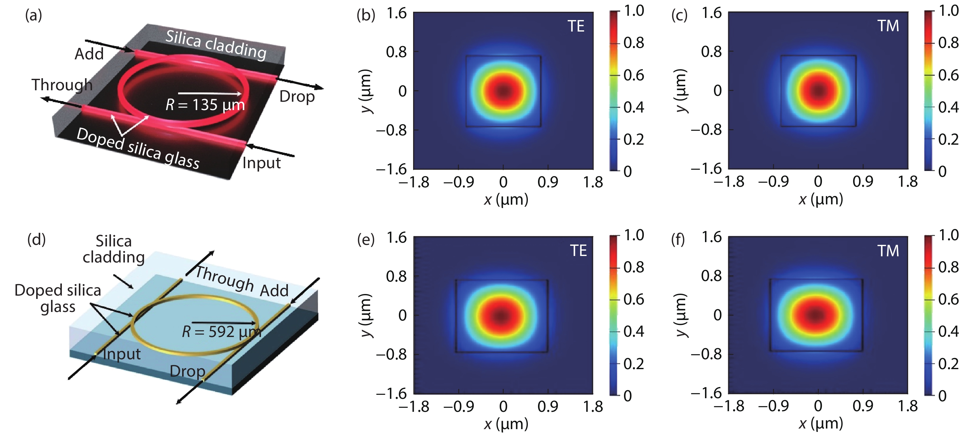
    Fig. 1. (Color online) (a) Schematic illustration of the DP-MRR with FSR = 200 GHz. (b) TE and (c) TM mode profiles of the DP-MRR. (d), (e) and (f) corresponding results for FSR = 49 GHz MRR.
    (Color online) Experimental transmission spectra for the 49 GHz FSR MRR. (a) Through-port (cyan, yellow) and drop-port (blue, red) transmission spectra of TE and TM polarizations. (b) Drop-port transmission showing the FWHM resonances of 140 MHz, with Q > 1.2 × 10 6.
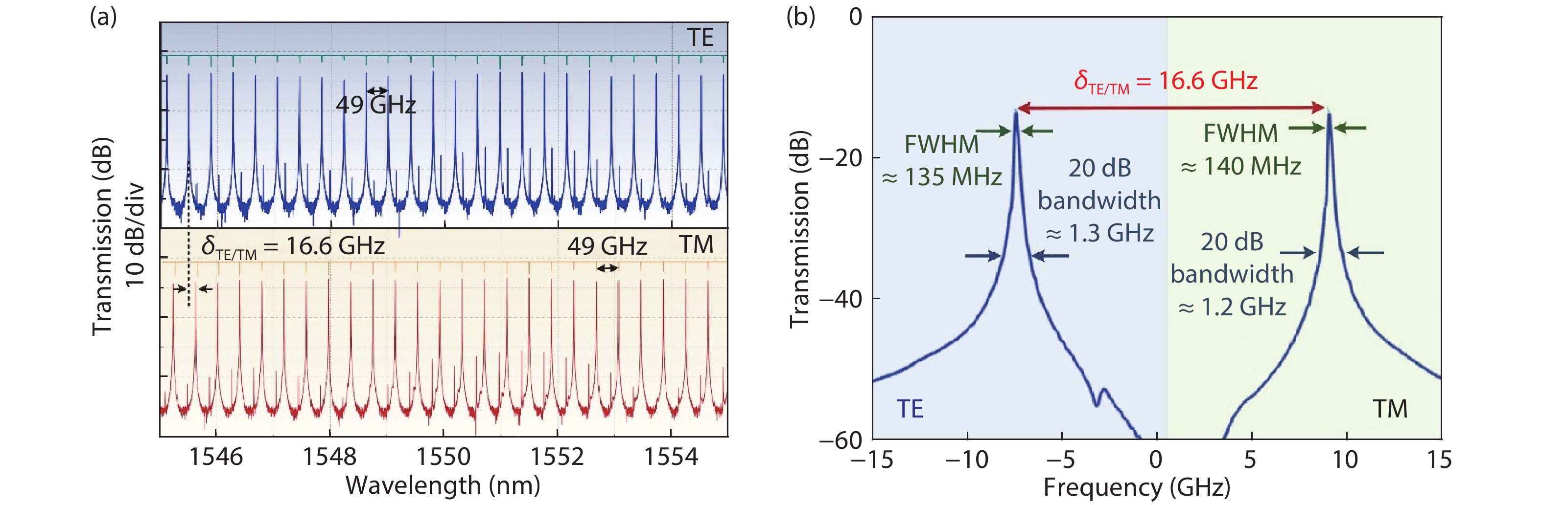
    Fig. 2. (Color online) Experimental transmission spectra for the 49 GHz FSR MRR. (a) Through-port (cyan, yellow) and drop-port (blue, red) transmission spectra of TE and TM polarizations. (b) Drop-port transmission showing the FWHM resonances of 140 MHz, with Q > 1.2 × 10 6.
    (Color online) (a, b) OSSB generator transmission spectra for temperatures from 23 to 30 °C. Relation between chip temperature and (c) resonance central wavelengths, (d) TE to TM resonance spacing.
    Fig. 3. (Color online) (a, b) OSSB generator transmission spectra for temperatures from 23 to 30 °C. Relation between chip temperature and (c) resonance central wavelengths, (d) TE to TM resonance spacing.
    (Color online) Measured transmission spectra of the (49 GHz FSR MRR) and 200 GHz FSR MRR.
    Fig. 4. (Color online) Measured transmission spectra of the (49 GHz FSR MRR) and 200 GHz FSR MRR.
    (Color online) Principle of operation of the orthogonally polarized optical single sideband (OSSB) generator. EOM: electro-optical modulator. OSA: optical spectrum analyzer. PC: polarization controller. POL: optical polarizer. LD: laser diode. DSB: double sideband. DP-MRR: dual-polarization-mode micro-ring resonator. OCSR: optical carrier to sideband ratio. (i) The 45° polarized carrier is modulated with dual side-bands. (ii) The carrier is transmitted by the DP-MRR TM resonance and the upper sideband is passed by the DP-MRR TE resonance while the lower sideband is rejected by the DP-MRR. (iii) A polarizer extracts the 45° components of both upper sideband and carrier, projecting the SSB signal onto a single polarization.
    Fig. 5. (Color online) Principle of operation of the orthogonally polarized optical single sideband (OSSB) generator. EOM: electro-optical modulator. OSA: optical spectrum analyzer. PC: polarization controller. POL: optical polarizer. LD: laser diode. DSB: double sideband. DP-MRR: dual-polarization-mode micro-ring resonator. OCSR: optical carrier to sideband ratio. (i) The 45° polarized carrier is modulated with dual side-bands. (ii) The carrier is transmitted by the DP-MRR TM resonance and the upper sideband is passed by the DP-MRR TE resonance while the lower sideband is rejected by the DP-MRR. (iii) A polarizer extracts the 45° components of both upper sideband and carrier, projecting the SSB signal onto a single polarization.
    (Color online) Optical spectra of the generated orthogonally polarized OSSB signal.
    Fig. 6. (Color online) Optical spectra of the generated orthogonally polarized OSSB signal.
    (Color online) Transmission spectra of the OSSB generator with (a) θ = 2°, (b) θ = 42°, (c) θ = 92°, where θ denotes the polarization angle as shown in Fig. 4. (d)–(f) are zoom-in views of the shaded areas in (a)–(c), respectively.
    Fig. 7. (Color online) Transmission spectra of the OSSB generator with (a) θ = 2°, (b) θ = 42°, (c) θ = 92°, where θ denotes the polarization angle as shown in Fig. 4. (d)–(f) are zoom-in views of the shaded areas in (a)–(c), respectively.
    (Color online) (a) OSSB generator transmission spectra for θ from 2° to 92°, and (b) TE to TM resonance extinction ratio labeled “TE”, “TM1” and “TM2” in Fig. 7(a), corresponding to 16.6 and 32.4 GHz RF operation, respectively.
    Fig. 8. (Color online) (a) OSSB generator transmission spectra for θ from 2° to 92°, and (b) TE to TM resonance extinction ratio labeled “TE”, “TM1” and “TM2” in Fig. 7(a), corresponding to 16.6 and 32.4 GHz RF operation, respectively.
    (Color online) OSSB generated signal optical spectra with a continuously tuneable optical carrier-to-sideband ratio (OCSR) driven by RF signals at (a) 16.6 and (b) 32.4 GHz. The 16.6 and 32.4 GHz RF sidebands were dropped via the “TM2” and “TM1” resonances, while the optical carrier was dropped by the “TE” resonance, as marked.
    Fig. 9. (Color online) OSSB generated signal optical spectra with a continuously tuneable optical carrier-to-sideband ratio (OCSR) driven by RF signals at (a) 16.6 and (b) 32.4 GHz. The 16.6 and 32.4 GHz RF sidebands were dropped via the “TM2” and “TM1” resonances, while the optical carrier was dropped by the “TE” resonance, as marked.
    (Color online) Principle of operation of the RF photonic equalizer using dual-polarization-mode ring resonators. PD: photo-detector. PM: phase modulator. PC: polarization controller. DP-MRR: LD: laser diode. dual-polarization-mode micro-ring resonator. VNA: vector network analyzer.
    Fig. 10. (Color online) Principle of operation of the RF photonic equalizer using dual-polarization-mode ring resonators. PD: photo-detector. PM: phase modulator. PC: polarization controller. DP-MRR: LD: laser diode. dual-polarization-mode micro-ring resonator. VNA: vector network analyzer.
    (Color online) RF transmission of a single passband with TM-polarized optical input.
    Fig. 11. (Color online) RF transmission of a single passband with TM-polarized optical input.
    (Color online) RF transmission of the single passband with varying (a) carrier wavelength, (b) chip temperature, and (c) input optical power. (d−f) Extracted centre frequency and 3 dB bandwidth.
    Fig. 12. (Color online) RF transmission of the single passband with varying (a) carrier wavelength, (b) chip temperature, and (c) input optical power. (d−f) Extracted centre frequency and 3 dB bandwidth.
    (Color online) RF transmission of the proposed equalizer with variable operation frequencies achieved by tuning (a) carrier wavelength and (b) chip temperature. (c, d) Extracted corresponding center frequencies of the TE- and TM-passbands.
    Fig. 13. (Color online) RF transmission of the proposed equalizer with variable operation frequencies achieved by tuning (a) carrier wavelength and (b) chip temperature. (c, d) Extracted corresponding center frequencies of the TE- and TM-passbands.
    (Color online) (a) Transmission spectra of the optical through-port and drop-port of the DP-MRR and (b) RF transmission of the equalizer with extinction ratio between TM and TE passbands as the input light polarization angle θ changes from 0° to 90°. fTM−fTE denotes the spacing between the TM-passband and TE-passband, which is wideband tuneable (Fig. 12) and in this plot is 4.8 GHz.
    Fig. 14. (Color online) (a) Transmission spectra of the optical through-port and drop-port of the DP-MRR and (b) RF transmission of the equalizer with extinction ratio between TM and TE passbands as the input light polarization angle θ changes from 0° to 90°. fTMfTE denotes the spacing between the TM-passband and TE-passband, which is wideband tuneable (Fig. 12) and in this plot is 4.8 GHz.
    (Color online) OP-OSSB (orthogonally polarized optical single sideband) generator schematic. LD: laser diode. OSA: optical spectrum analyzer. EOM: electro-optical modulator. VNA: vector network analyzer. DSB: double sideband PC: polarization controller. OPM: optical power meter. 45° POL: optical polarizer with the polarization direction having an angle of 45° to the TM axis. PD: photodetector. RFG: RF generator.
    Fig. 15. (Color online) OP-OSSB (orthogonally polarized optical single sideband) generator schematic. LD: laser diode. OSA: optical spectrum analyzer. EOM: electro-optical modulator. VNA: vector network analyzer. DSB: double sideband PC: polarization controller. OPM: optical power meter. 45° POL: optical polarizer with the polarization direction having an angle of 45° to the TM axis. PD: photodetector. RFG: RF generator.
    (Color online) (a) Measured transmission spectra of the 49 GHz (TM) MRR, 200 GHz FSR (TE) MRR, and the combined OP-OSSB generator. (b) Zoom-in spectra of (a) with one TE polarized resonance and one TM polarized resonance. (c) Transmission spectra around one TM-polarized resonance of the 49 GHz FSR MRR.
    Fig. 16. (Color online) (a) Measured transmission spectra of the 49 GHz (TM) MRR, 200 GHz FSR (TE) MRR, and the combined OP-OSSB generator. (b) Zoom-in spectra of (a) with one TE polarized resonance and one TM polarized resonance. (c) Transmission spectra around one TM-polarized resonance of the 49 GHz FSR MRR.
    (Color online) Optical spectra of the generated orthogonally polarized OSSB signal.
    Fig. 17. (Color online) Optical spectra of the generated orthogonally polarized OSSB signal.
    (Color online) (a) Measured transmission spectra of the dual MRRs and (b, c) optical spectra of the generated orthogonally polarized OSSB signal with continuously tunable OCSR.
    Fig. 18. (Color online) (a) Measured transmission spectra of the dual MRRs and (b, c) optical spectra of the generated orthogonally polarized OSSB signal with continuously tunable OCSR.
    (Color online) (a) Measured optical transmission spectra, and (b) RF transmission response of the OP-OSSB generator with thermo-optical control.
    Fig. 19. (Color online) (a) Measured optical transmission spectra, and (b) RF transmission response of the OP-OSSB generator with thermo-optical control.
    (Color online) (a) Optical spectra and (b) extracted operation RF frequency of the generated OP-OSSB signals with thermal tuning.
    Fig. 20. (Color online) (a) Optical spectra and (b) extracted operation RF frequency of the generated OP-OSSB signals with thermal tuning.
    Mengxi Tan, Xingyuan Xu, Jiayang Wu, Thach G. Nguyen, Sai T. Chu, Brent E. Little, Arnan Mitchell, Roberto Morandotti, David J. Moss. Orthogonally polarized RF optical single sideband generation with integrated ring resonators[J]. Journal of Semiconductors, 2021, 42(4): 041305
    Download Citation