
Mengxi Tan, Xingyuan Xu, Jiayang Wu, Thach G. Nguyen, Sai T. Chu, Brent E. Little, Arnan Mitchell, Roberto Morandotti, David J. Moss. Orthogonally polarized RF optical single sideband generation with integrated ring resonators[J]. Journal of Semiconductors, 2021, 42(4): 041305
- Journal of Semiconductors
- Vol. 42, Issue 4, 041305 (2021)
Abstract
1. Introduction
Photonic microwave and radio frequency (RF) signal processing[
For RF photonic-based systems, the optical RF signal modulation format directly impacts its transmission capacity as well as its spectral efficiency. Hence, this is a key factor in the design of state-of-the-art photonic RF transmitters[
Other key components for RF systems are RF equalizers, which compensate any imbalance in passive component frequency responses or variations in the gain profile of RF amplifiers[
We review recent work on orthogonally polarized OSSB generation and a dual-channel RF equalizer[
2. Integrated microring resonators
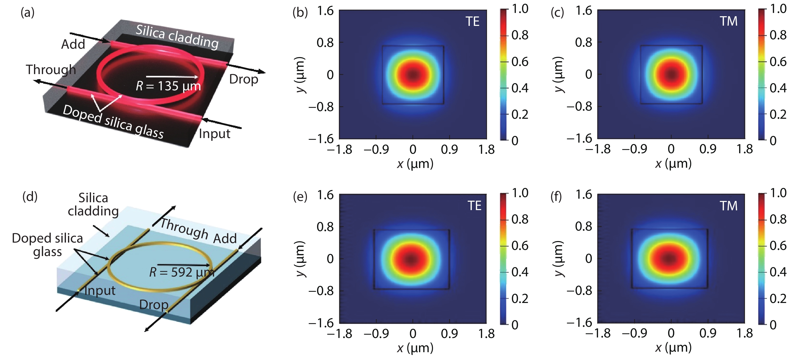
The integrated micro-ring resonators (Fig. 1) that formed the core components of the system were based on Hydex glass, a high-index doped silica platform that features CMOS compatible processes[
![]()
Figure 1.(Color online) (a) Schematic illustration of the DP-MRR with FSR = 200 GHz. (b) TE and (c) TM mode profiles of the DP-MRR. (d), (e) and (f) corresponding results for FSR = 49 GHz MRR.
![]()
Figure 2.(Color online) Experimental transmission spectra for the 49 GHz FSR MRR. (a) Through-port (cyan, yellow) and drop-port (blue, red) transmission spectra of TE and TM polarizations. (b) Drop-port transmission showing the FWHM resonances of 140 MHz, with
The ring resonators can be tuned thermally to match any optical carrier wavelength, to a resolution of less than 0.01 °C, equivalent to megahertz level resolution, and with a response time on the order of milliseconds[
![]()
Figure 3.(Color online) (a, b) OSSB generator transmission spectra for temperatures from 23 to 30 °C. Relation between chip temperature and (c) resonance central wavelengths, (d) TE to TM resonance spacing.
For the orthogonally polarized OSSB system that was continuously tunable[
![]()
Figure 4.(Color online) Measured transmission spectra of the (49 GHz FSR MRR) and 200 GHz FSR MRR.
3. Orthogonally polarized optical single sideband generator
The architecture of the orthogonally polarized OSSB generator is shown in Fig. 5. As discussed, the rings were designed to support both polarizations, and yet still with a significant mode refractive index difference between them. We modulated a tunable CW laser to produce double sidebands (DSB). The signal was then coupled into the DP-MRR with a polarization angle of 45° to the TE-axis [Fig. 5(i)]. When the wavelength of the pump and the RF frequency of the signal were each equal to one of the two orthogonally polarized DP-MRR resonances, one generated DSB sideband together with the optical carrier signal were dropped by the TE/TM resonances, thus producing orthogonally polarized OSSB modulated signals [Fig. 5(ii)]. Further, we controlled the relative fraction of TE versus TM light for the orthogonally polarized OSSB signal by passing the signal through a polarizer and adjusting the polarization angle. This had the effect of tuning the optical carrier to sideband ratio (OCSR) for the single polarization OSSB modulated signal.
![]()
Figure 5.(Color online) Principle of operation of the orthogonally polarized optical single sideband (OSSB) generator. EOM: electro-optical modulator. OSA: optical spectrum analyzer. PC: polarization controller. POL: optical polarizer. LD: laser diode. DSB: double sideband. DP-MRR: dual-polarization-mode micro-ring resonator. OCSR: optical carrier to sideband ratio. (i) The 45° polarized carrier is modulated with dual side-bands. (ii) The carrier is transmitted by the DP-MRR TM resonance and the upper sideband is passed by the DP-MRR TE resonance while the lower sideband is rejected by the DP-MRR. (iii) A polarizer extracts the 45° components of both upper sideband and carrier, projecting the SSB signal onto a single polarization.
The effective index difference between the polarizations yielded a strong dependence on polarization in the DP-MRR transmission spectrum. We employed the Jones matrix approach, where the eigenmodes of the DP-MRR are the polarization states that provide a natural basis. Hence, the drop-port transmission of the DP-MRR becomes
where DTM and DTE and are the drop-port transfer functions of the TM and TE modes given by
where k and t are the cross-coupling and transmission coefficients between the micro-ring and bus waveguide (t2 + k2 = 1 for zero loss coupling), a is the transmission for a round-trip, ϕTM = 2πLneff_TM/λ and ϕTE = 2πLneff_TE/λ are phase shifts for a single-pass of the TM and TE modes, respectively, and L is the length of the round-trip, and neff_TM and neff_TE are the effective indices for the TM and TE modes.
The polarizer Jones matrix is
with θ being the angle between the TM axis and the direction of the polarize. For a general input field
where the input φTM and φTE are the complex phase angles of DTM and DTE.
Hence, the dropped optical output power or induced loss due to polarization conversion by the TM and TE resonances is ~ cos2θ or sin2θ, respectively. Specifically, when θ = 45°, the polarization conversion induced loss is 3 dB for both polarizations. The OCSR (with the carrier using the TM resonance and upper sideband the TE resonance) is
which can be tuned continuously by varying θ. Further, since cot2θ can be adjusted arbitrarily close to 0 or 1 as θ approaches π/2 or 0, a very high OCSR dynamic tuning range is obtained.
For the experiments, we tuned the laser to the 1550.47 nm TE resonance and modulated it in intensity at frequencies of 16.6 or 32.4 GHz with an RF signal generator, so that both the lower and upper sidebands could be filtered out by the adjacent TM resonance on the carrier’s long (red) or short (blue) wavelength sides. The orthogonally polarized carrier and the sidebands were both obtained from the drop-port of the DP-MRR, with the optical power of the discarded sideband being attenuated by > 35 dB in comparison with the signal sideband ( Fig. 6).
![]()
Figure 6.(Color online) Optical spectra of the generated orthogonally polarized OSSB signal.
Next, we converted the orthogonally polarized OSSB signal to a single polarized OSSB signal via a polarizer, and by adjusting the polarizer angle we were able to vary the OCSR. The transmission spectra of the OSSB generator with tunable OCSR is shown in Fig. 7. As θ was tuned from 2° to 92°, the TE and TM extinction ratio varied from 30 to –29 dB, yielding a tuning range for the OCSR of 59.3 dB. The extinction ratios [Figs. 7(d)–7(f)] clearly show that an RF operation frequency as high as 32.4 GHz was achieved. The resulting extinction ratios and transmission spectra (Fig. 8) for RF operation at 16.6 and 32.4 GHz, show that with a polarization angle varied from 2° to 92°, good agreement was achieved with the theory. From Fig. 8(b), a large dynamic range of 80 dB is anticipated and this can be accomplished by varying θ with a much finer resolution.
![]()
Figure 7.(Color online) Transmission spectra of the OSSB generator with (a)
![]()
Figure 8.(Color online) (a) OSSB generator transmission spectra for
The generated 16.6 and 32.4 GHz single-polarization OSSB optical spectra signals (Fig. 9) show that a continuously tunable OCSR is achieved, with a range of −22.7 to 41.4 dB and −27.1 to 52.2 dB. This illustrates the high performance and practicality of the OSSB generator that features a tunable OCSR. Finally, carrier to sideband shifts of greater than one FSR can result in larger RF frequencies with the same device, which in our case correspond to 65.6 GHz = 16.6 GHz + FSR and 81.4 GHz = 32.4 GHz + FSR, and so on for higher frequencies.
![]()
Figure 9.(Color online) OSSB generated signal optical spectra with a continuously tuneable optical carrier-to-sideband ratio (OCSR) driven by RF signals at (a) 16.6 and (b) 32.4 GHz. The 16.6 and 32.4 GHz RF sidebands were dropped via the “TM2” and “TM1” resonances, while the optical carrier was dropped by the “TE” resonance, as marked.
The fact that the ring resonators had quite a high Q of over a million meant that the device achieved a high RF selectivity for the OSSB generation. In principle this could yield a self-oscillating source at high frequency that operates through optoelectronic oscillation, which is a powerful approach to obtain a very low phase noise. This is important for many applications, such as delivery of RF standards over long-distances. In this regard, the OSSB modulation format excels since it is immune to RF power fading arising from all dispersion effects. Hence our device can be applied to a very wide range of technical fields including even telescope arrays for radio astronomy.
4. RF equalizer
Here we turn to the RF photonic equalizer that was also based on the DP-MRRs (Fig. 10). For this device, an RF signal was used to phase modulate a CW tunable laser, which produced dual sidebands that had opposite phases, and with an angle of θ between the TE-axis and polarization direction [Fig. 10(i)]. Next, the TE and TM phase-modulated signal components were filtered out by the two orthogonally polarized ring resonances (notches) [Fig. 10(ii)], where the imbalance between the two oppositely phased sidebands was produced in order to convert from phase to intensity modulation. Following this, the filtered orthogonally polarized optical signals were converted to RF signals and then combined after photodetection. Effectively, therefore, the high-Q orthogonally polarized optical resonances were translated into the RF domain [Fig. 10(iii)], which resulted in a high RF frequency selective filter with dual passbands and with a bandwidth determined by the Q factor of the DP-MRR. The center frequencies were given by the relative spacing of the optical carrier to the adjacent resonance. By varying the polarization angle θ, the fraction of TM to TE light was varied continuously, with an extinction ratio between the dual RF passbands able to be tuned to perform RF equalization after mapping the optical signal to the RF domain[
![]()
Figure 10.(Color online) Principle of operation of the RF photonic equalizer using dual-polarization-mode ring resonators. PD: photo-detector. PM: phase modulator. PC: polarization controller. DP-MRR: LD: laser diode. dual-polarization-mode micro-ring resonator. VNA: vector network analyzer.
The DP-MRR transmission through-port is
where TTE and TTM are the through-port transfer functions of the DP-MRR given by
For a phase modulated optical signal
This equation shows that the RF passband center frequencies supported by the TE/TM resonances are determined by the relative frequency gap between the MRR resonances and the optical carrier, thus yielding tunable operation regions for the RF equalizer. Moreover, the TE and TM polarized optical signal power is ~ cos2θ or sin2θ, respectively. Hence, after being detected, the RF passband extinction ratio (corresponding to the DP-MRR’s TE- and TM-polarized resonances) is given by
Similarly to the tunable OCSR for OSSB generation, the ER(θ) can be continuously varied by adjusting θ, and since cot2θ can get arbitrarily, close to 1 or 0 as θ nears 0 or π/2 (limited only by the polarizer performance), the result is a large extinction ratio tuning range results, reflecting a very large RF equalization dynamic range.
The experiments first investigated the tunability and resolution of a single RF passband by setting the input optical signal to be TM-polarized (θ = 90°). The RF transmission spectra is shown in Fig. 11, measured with a vector network analyser. The 3 dB-bandwidth of the passband is 137.1 MHz, which defines the resolution of the RF equalizer. The passband’s centre frequency tunability was accomplished via adjusting the carrier wavelength [Figs. 12(a) and 12(b)], the DP-MRR chip temperature [Figs. 12(c) and 12(d)], and optical power [Figs. 12(e) and 12(f)]. As seen, all these methods of tuning can readily shift the RF passband central frequency (3 dB-bandwidth of ~140 MHz), thus achieving tunability of the RF high-resolution equalizer.
![]()
Figure 11.(Color online) RF transmission of a single passband with TM-polarized optical input.
![]()
Figure 12.(Color online) RF transmission of the single passband with varying (a) carrier wavelength, (b) chip temperature, and (c) input optical power. (d−f) Extracted centre frequency and 3 dB bandwidth.
We varied the operation frequency of the RF equalizer by tuning the carrier wavelength [Figs. 13(a) and 13(b)] as well as the temperature of the ring [Figs. 13(c) and 13(d)]. This yielded a continuous frequency range coverage of more than 14.6 GHz. The TM and TE resonances supported the extracted RF passband centre frequencies [the TM and TE centre frequencies in Figs. 13(b) and 13(d)], showing the effectiveness of each approach to tuning. Tuning the RF TE to TM passband extinction ratios was accomplished by adjusting the angle of the polarized light θ (Fig. 10). The measured optical drop-port and through-port transmission spectra of the DP-MRR are shown versus θ in Fig. 14(a). Due to a limited resolution for the tuning angle, the TM and TE through-port transmission notches could not be properly resolved, and so we also measured the drop-port transmission. We achieved an extinction ratio between the two RF dual-channel equalizer passbands with a wide tuning range [Fig. 14(b)] of −27.4 to 28.2 dB, equivalent to a dynamic range > 55 dB. This demonstrates the very high-performance capability of our device.
![]()
Figure 13.(Color online) RF transmission of the proposed equalizer with variable operation frequencies achieved by tuning (a) carrier wavelength and (b) chip temperature. (c, d) Extracted corresponding center frequencies of the TE- and TM-passbands.
![]()
Figure 14.(Color online) (a) Transmission spectra of the optical through-port and drop-port of the DP-MRR and (b) RF transmission of the equalizer with extinction ratio between TM and TE passbands as the input light polarization angle
The work that we review here focused on narrowband signals for optical single sideband generation as well as RF equalisation with a high-resolution. However, in many cases, signals that have a broad RF bandwidth need to be processed, and in this case either lower Q factor MRRs[
5. Continuously tuneable RF sideband generator
In this section we review our work based on a wideband tunable OP-OSSB generator[
![]()
Figure 15.(Color online) OP-OSSB (orthogonally polarized optical single sideband) generator schematic. LD: laser diode. OSA: optical spectrum analyzer. EOM: electro-optical modulator. VNA: vector network analyzer. DSB: double sideband PC: polarization controller. OPM: optical power meter. 45° POL: optical polarizer with the polarization direction having an angle of 45° to the TM axis. PD: photodetector. RFG: RF generator.
We use the Jones matrix formalism to analyze our device polarization states rather than other methods, such as the Stokes parameters or Poincaré sphere[
where DTE and DTM are the drop-port transfer functions of the 49 GHz (TE) MRR and 200 GHz (TM) MRR given by
where tTE, tTM, kTE and kTM are the field transmission and cross-coupling coefficients between the bus waveguide and the ring (t2 + k2 = 1 for lossless coupling), aTE and aTM represent the round-trip transmission factors, ϕTE = 2πLTEneff_TE/λ and ϕTM = 2πLTMneff_TM/λ are the single-pass phase shifts of the TE-MRR and TM-MRR, respectively, with LTE and LTM denoting the round-trip length, neff_TE and neff_TM representing the effective indices, with λ the wavelength.
For a general optical input field
From this equation, the optical power of the spectral components dropped by the 49 GHz (TE) MRR and 200 GHz (TM) MRR are proportional to cos2θ and sin2θ, respectively. Thus, the OCSR (with the 49 GHz MRR for the carrier and the 200 GHz MRR for the sideband) is given by
which can be continuously tuned by adjusting θ. Since cot2θ can get arbitrarily close to 1 or 0 as θ approaches 0 or π/2, a large OCSR tuning range can be achieved. Moreover, the generated OP-OSSB signal can be converted back into an RF signal by passing it through an optical polarizer [Fig. 15(iv)]. The RF frequency of the OP-OSSB generator is given by the spectral gap between adjacent resonances of the 49 and 200 GHz MRR. Thus, by separately controlling the MRRs, a tunable OP-OSSB generation can be realized over a large RF tuning range.
The two ring resonators were connected via polarization maintaining fiber pigtails, with the 49 GHz MRR through-port connected to the 200 GHz MRR input. Both ring’s drop-ports were then combined by connecting the 200 GHz (TE) MRR drop-port to the 49 GHz (TM) MRR add-port. Fig. 16 shows the experimental transmission spectra of the dual MRRs. As reflected by the dual resonances, both MRRs supported two polarizations. The 49 GHz spaced ring (first) and the 200 GHz FSR ring (second) acted as TM and TE filters for the OP-OSSB generation, respectively. The RF operation frequency was determined by the spectral interval between orthogonally polarized adjacent resonances [Fig. 16(b)]. The 49 GHz MRR had a high Q, with a 1.04 GHz bandwidth at –20 dB [Fig. 16(b)] for the OP-OSSB generator, reflecting a very high optical carrier rejection ratio and lower accessible RF frequency down below a Gigahertz.
![]()
Figure 16.(Color online) (a) Measured transmission spectra of the 49 GHz (TM) MRR, 200 GHz FSR (TE) MRR, and the combined OP-OSSB generator. (b) Zoom-in spectra of (a) with one TE polarized resonance and one TM polarized resonance. (c) Transmission spectra around one TM-polarized resonance of the 49 GHz FSR MRR.
For this device the carrier wavelength was tuned to one of the TE 200 GHz MRR resonances at ~1549.78 nm, and then the RF signal was used to drive the intensity modulator so that the adjacent TM resonance of the 49 GHz MRR dropped the lower sideband. The orthogonally polarized carrier and lower sideband were extracted at the output of the dual MRRs, where the upper sideband optical power was suppressed by > 35 dB in comparison with the lower sideband ( Fig. 17).
![]()
Figure 17.(Color online) Optical spectra of the generated orthogonally polarized OSSB signal.
The orthogonally polarized optical carrier to lower sideband ratio could be adjusted by varying the polarization input angle (θ in Fig. 15). The measured dual MRR transmission [Fig. 18(a)] versus polarization angle θ shows that the TE to TM extinction ratio varied from 20.5 dB to –31.1 dB, equating to a dynamic OSCR tuning range of 51.1 dB. The generated OP-OSSB signal optical spectra with at RF frequencies of 19.7 and 26.6 GHz is shown in Figs. 18(b) and 18(c). An OCSR that is continuously variable from −21.1 to 36.2 dB and −18.1 to 38.9 dB was obtained, respectively, for the 19.7 and 26.6 GHz RF inputs, yielding a large OCSR tuning range of 57.3 dB. The cascaded MRR orthogonal polarization modes could also potentially offer an extra control mechanism for optical logic gates as an innovative approach to optical computing[
![]()
Figure 18.(Color online) (a) Measured transmission spectra of the dual MRRs and (b, c) optical spectra of the generated orthogonally polarized OSSB signal with continuously tunable OCSR.
To achieve wide RF tunability, the frequency difference between the TM 49 GHz ring resonances and the TE 200 GHz MRR resonances were tuned via separate thermal control[
![]()
Figure 19.(Color online) (a) Measured optical transmission spectra, and (b) RF transmission response of the OP-OSSB generator with thermo-optical control.
![]()
Figure 20.(Color online) (a) Optical spectra and (b) extracted operation RF frequency of the generated OP-OSSB signals with thermal tuning.
Because the cascaded micro-ring resonators are passive, they did not have any impact on the system performance regarding coherence or dephasing time. The generated signal dephasing time was mainly determined by the coherence length of our laser Lcoh, which is given by[
where λ is the source wavelength (~1550 nm), n is the fiber refractive index (~1.45), and Δλ is the FWHM of the source spectral width. Our laser had a 400 kHz FWHM spectral width, yielding a coherence length of ~414 m.
For this tuneable OP-OSSB generator, the ring resonators that we used had quite high Q factors, suitable for generating relatively narrow band (albeit high frequency) RF signals. For applications to RF broadband signals, one can either use lower Q factor ring resonators[
In terms of fabrication tolerances and manufacturability, we note that the Hydex platform is CMOS compatible and was originally developed for extremely demanding applications in commercial wavelength division multiplexed optical communications systems for advanced filter design[
6. Conclusion
We review recent work on fixed and tunable orthogonally polarized optical single sideband (OSSB) generators as well as a dual-channel RF equalizer, both based on integrated dual polarization micro-ring resonators. By controlling the fabrication of the micro-rings, the refractive index of the ring resonator TE and TM polarized modes were engineered to produce a spacing of 16.6 GHz in the C-band. At the drop-port, the optical carrier and sideband were separated by the orthogonally polarized resonances to achieve orthogonally-polarized OSSB modulation. At the through-port, on the other hand, the transmission notches allowed dual-channel RF filtering via phase-to-intensity modulation conversion for equalization. We achieved a large dynamic tuning range of the optical carrier-to-sideband ratio of the OSSB signal and the dual-channel RF equalization by controlling the polarization angle. Our method represents a novel way of achieving OSSB generation as well as photonic RF equalization, while offering a compact footprint and high performance. This approach is promising for radar and communications systems RF photonic signal processing.
References
[1] J Capmany, D Novak. Microwave photonics combines two worlds. Nat Photonics, 1, 319(2007).
[2] J P Yao. Microwave photonics. J Lightwave Technol, 27, 314(2009).
[3] K Xu, R X Wang, Y T Dai et al. Microwave photonics: Radio-over-fiber links, systems, and applications. Photon Res, 2, B54(2014).
[4] U Gliese, S Norskov, T N Nielsen. Chromatic dispersion in fiber-optic microwave and millimeter-wave links. IEEE Trans Microw Theory Tech, 44, 1716(1996).
[5] Y M Zhang, F Z Zhang, S L Pan. Optical single sideband modulation with tunable optical carrier-to-sideband ratio. IEEE Photonics Technol Lett, 26, 653(2014).
[6] S R Blais, J P Yao. Optical single sideband modulation using an ultranarrow dual-transmission-band fiber Bragg grating. IEEE Photonics Technol Lett, 18, 2230(2006).
[7] D Q Feng, J Q Sun. Optical single sideband modulation based on a high-order birefringent filter using cascaded Solc-Sagnac and Lyot-Sagnac loops. Opt Lett, 41, 3659(2016).
[8] Y C Shen, X M Zhang, K S Chen. Optical single sideband modulation of 11-GHz RoF system using stimulated Brillouin scattering. IEEE Photonics Technol Lett, 17, 1277(2005).
[9] B Hraimel, X P Zhang, Y Q Pei et al. Optical single-sideband modulation with tunable optical carrier to sideband ratio in radio over fiber systems. J Lightwave Technol, 29, 775(2011).
[10] M Xue, S L Pan, Y J Zhao. Optical single-sideband modulation based on a dual-drive MZM and a 120° hybrid coupler. J Lightwave Technol, 32, 3317(2014).
[11] X Y Xu, J Y Wu, T G Nguyen et al. Photonic microwave true time delays for phased array antennas using a 49 GHz FSR integrated optical micro-comb source. Photon Res, 6, B30(2018).
[12] X X Xue, Y Xuan, H J Kim et al. Programmable single-bandpass photonic RF filter based on kerr comb from a microring. J Lightwave Technol, 32, 3557(2014).
[13] X Y Xu, J Y Wu, T G Nguyen et al. Advanced RF and microwave functions based on an integrated optical frequency comb source. Opt Express, 26, 2569(2018).
[14] T G Nguyen, M Shoeiby, S T Chu et al. Integrated frequency comb source based Hilbert transformer for wideband microwave photonic phase analysis. Opt Express, 23, 22087(2015).
[15] X Y Xu, J Y Wu, T G Nguyen et al. Broadband RF channelizer based on an integrated optical frequency kerr comb source. J Lightwave Technol, 36, 4519(2018).
[16] M Ferrera, C Reimer, A Pasquazi et al. CMOS compatible integrated all-optical radio frequency spectrum analyzer. Opt Express, 22, 21488(2014).
[17] B Corcoran, T D Vo, M D Pelusi et al. Silicon nanowire based radio-frequency spectrum analyzer. Opt Express, 18, 20190(2010).
[18] M Pelusi, F Luan, T D Vo et al. Photonic-chip-based radio-frequency spectrum analyser with terahertz bandwidth. Nat Photonics, 3, 139(2009).
[19] X Y Xu, J Y Wu, M X Tan et al. Orthogonally polarized RF optical single sideband generation and dual-channel equalization based on an integrated microring resonator. J Lightwave Technol, 36, 4808(2018).
[20] X Xu, J Wu, T G Nguyen et al. Continuously tunable orthogonally polarized optical RF single sideband generator and equalizer based on an integrated micro-ring resonator. J Opt, 20, 115701(2018).
[21] M X Tan, X Y Xu, B Corcoran et al. Microwave and RF photonic fractional Hilbert transformer based on a 50 GHz Kerr micro-comb. J Lightwave Technol, 37, 6097(2019).
[22] X Y Xu, M X Tan, J Y Wu et al. Advanced adaptive photonic RF filters with 80 taps based on an integrated optical micro-comb source. J Lightwave Technol, 37, 1288(2019).
[23] X Y Xu, M X Tan, J Y Wu et al. High performance RF filters via bandwidth scaling with Kerr micro-combs. APL Photonics, 4, 026102(2019).
[24] X Y Xu, M X Tan, J Y Wu et al. Microcomb-based photonic RF signal processing. IEEE Photonics Technol Lett, 31, 1854(2019).
[25] X Y Xu, M X Tan, J Wu et al. Photonic RF phase-encoded signal generation with a microcomb source. J Lightwave Technol, 38, 1722(2020).
[26] X Y Xu, J Y Wu, M X Tan et al. Broadband microwave frequency conversion based on an integrated optical micro-comb source. J Lightwave Technol, 38, 332(2020).
[27] M X Tan, X Y Xu, B Corcoran et al. RF and microwave fractional differentiator based on photonics. IEEE Trans Circuits Syst II, 67, 2767(2020).
[28] X Y Xu, M X Tan, B Corcoran et al. Photonic perceptron based on a kerr microcomb for high-speed, scalable, optical neural networks. Laser Photonics Rev, 14, 2000070(2020).
[29] M X Tan, X Y Xu, J Y Wu et al. Photonic RF and microwave filters based on 49 GHz and 200 GHz Kerr microcombs. Opt Commun, 465, 125563(2020).
[30] X Y Xu, M X Tan, J Y Wu et al. Photonic RF and microwave integrator based on a transversal filter with soliton crystal microcombs. IEEE Trans Circuits Syst II, 67, 3582(2020).
[31] X Y Xu, M X Tan, J Y Wu et al. Broadband photonic RF channelizer with 92 channels based on a soliton crystal microcomb. J Lightwave Technol, 38, 5116(2020).
[32] M Tan, X Xu, A Boes et al. Photonic RF arbitrary waveform generator based on a soliton crystal micro-comb source. J Lightwave Technol, 38, 6221(2020).
[33] B Corcoran, M X Tan, X Y Xu et al. Ultra-dense optical data transmission over standard fibre with a single chip source. Nat Commun, 11, 2568(2020).
[34] J Wu, X Xu, T G Nguyen et al. RF photonics: An optical microcombs’ perspective. IEEE J Sel Top Quantum, 24, 1(2018).
[35] X Y Xu, J Y Wu, M Shoeiby et al. Reconfigurable broadband microwave photonic intensity differentiator based on an integrated optical frequency comb source. APL Photonics, 2, 096104(2017).
[36] M Tan, u X Xu, u J Wu et al. RF and microwave photonic temporal signal processing with Kerr micro-combs. Adv Phys X, 6, 1838946(2021).
[37] X Xu, M Tan, B Corcoran et al. 11 TOPS photonic convolutional accelerator for optical neural networks. Nature, 589, 44(2021).
[38] S L Pan, Y M Zhang. Tunable and wideband microwave photonic phase shifter based on a single-sideband polarization modulator and a polarizer. Opt Lett, 37, 4483(2012).
[39] L Wang, W Li, H Wang et al. Photonic generation of phase coded microwave pulses using cascaded polarization modulators. IEEE Photonics Technol Lett, 25, 678(2013).
[40] L Wang, W Li, J Zheng et al. High-speed microwave photonic switch for millimeter-wave ultra-wideband signal generation. Opt Lett, 38, 579(2013).
[41] Z H Li, C Y Yu, Y Dong et al. Linear photonic radio frequency phase shifter using a differential-group-delay element and an optical phase modulator. Opt Lett, 35, 1881(2010).
[42] B Vidal, T Mengual, C Ibanez-Lopez et al. Optical beamforming network based on fiber-optical delay lines and spatial light modulators for large antenna arrays. IEEE Photonics Technol Lett, 18, 2590(2006).
[43] J Y Zheng, L X Wang, Z Dong et al. Orthogonal single-sideband signal generation using improved Sagnac-loop-based modulator. IEEE Photonics Technol Lett, 26, 2229(2014).
[44] W Wang, J Liu, H Mei et al. Phase-coherent orthogonally polarized optical single sideband modulation with arbitrarily tunable optical carrier-to-sideband ratio. Opt Express, 24, 388(2016).
[45] Y M Zhang, F Z Zhang, S L Pan. Optical single sideband polarization modulation for radio-over-fiber system and microwave photonic signal processing. Photon Res, 2, B80(2014).
[46] A L Campillo. Orthogonally polarized single sideband modulator. Opt Lett, 32, 3152(2007).
[47] M Sagues, A Loayssa. Orthogonally polarized optical single sideband modulation for microwave photonics processing using stimulated Brillouin scattering. Opt Express, 18, 22906(2010).
[48] W Li, N Zhu, L Wang. Perfectly orthogonal optical single-sideband signal generation based on stimulated Brillouin scattering. IEEE Photonics Technol Lett, 24, 751(2012).
[49] L Nebuloni, G Orsenigo. Microwave power module for space applications. IEEE Trans Electron Devices, 48, 88(2001).
[50] H Wang, B Yan, Z G Wang et al. A broadband microwave gain equalizer. PIER Lett, 33, 63(2012).
[51] S X Wang, Y F Wang, D W Zhang et al. Design of tunable equalizers using multilayered half mode substrate integrated waveguide structures added absorbing Pillars. Adv Mater Sci Eng, 2015, 1(2015).
[52] D W Zhang, Q Liu, Z Dongfang et al. A gain equalizer based on dual-mode circular substrate integrated waveguide resonators. IEEE Microw Wirel Components Lett, 27, 539(2017).
[53] D Marpaung, C Roeloffzen, R Heideman et al. Integrated microwave photonics. Laser Photonics Rev, 7, 506(2013).
[54] W L Liu, M Li, R S Guzzon et al. A fully reconfigurable photonic integrated signal processor. Nat Photonics, 10, 190(2016).
[55] D J Moss, R Morandotti, A L Gaeta et al. New CMOS-compatible platforms based on silicon nitride and Hydex for nonlinear optics. Nat Photonics, 7, 597(2013).
[56] M Ferrera, L Razzari, D Duchesne et al. Low-power continuous-wave nonlinear optics in doped silica glass integrated waveguide structures. Nat Photonics, 2, 737(2008).
[57] M Peccianti, M Ferrera, L Razzari et al. Subpicosecond optical pulse compression via an integrated nonlinear chirper. Opt Express, 18, 7625(2010).
[58] L Razzari, D Duchesne, M Ferrera et al. CMOS-compatible integrated optical hyper-parametric oscillator. Nat Photonics, 4, 41(2010).
[59] A Pasquazi, M Peccianti, L Razzari et al. Micro-combs: A novel generation of optical sources. Phys Rep, 729, 1(2018).
[60] L Caspani, C Xiong, B Eggleton et al. On-chip sources of quantum correlated and entangled photons. Light: Sci Appl, 6, e17100(2017).
[61] M Kues, C Reimer, B Wetzel et al. Passively mode-locked laser with an ultra-narrow spectral width. Nat Photonics, 11, 159(2017).
[62] A Pasquazi, M Peccianti, B E Little et al. Stable, dual mode, high repetition rate mode-locked laser based on a microring resonator. Opt Express, 20, 27355(2012).
[63] A Pasquazi, L Caspani, M Peccianti et al. Self-locked optical parametric oscillation in a CMOS compatible microring resonator: A route to robust optical frequency comb generation on a chip. Opt Express, 21, 13333(2013).
[64] C Reimer, S Sciara, P Roztocki et al. High-dimensional one-way quantum processing implemented on d-level cluster states. Nat Phys, 15, 148(2019).
[65] M Kues, C Reimer, J M Lukens et al. Quantum optical microcombs. Nat Photonics, 13, 170(2019).
[66] A Pasquazi, M Peccianti, Y Park et al. Sub-picosecond phase-sensitive optical pulse characterization on a chip. Nat Photonics, 5, 618(2011).
[67] H L Bao, A Cooper, M Rowley et al. Laser cavity-soliton microcombs. Nat Photonics, 13, 384(2019).
[68] C Reimer, M Kues, L Caspani et al. Cross-polarized photon-pair generation and bi-chromatically pumped optical parametric oscillation on a chip. Nat Commun, 6, 8236(2015).
[69] L Caspani, C Reimer, M Kues et al. Multifrequency sources of quantum correlated photon pairs on-chip: A path toward integrated quantum frequency combs. Nanophotonics, 5, 351(2016).
[70] C Reimer, M Kues, P Roztocki et al. Generation of multiphoton entangled quantum states by means of integrated frequency combs. Science, 351, 1176(2016).
[71] M Kues, C Reimer, P Roztocki et al. On-chip generation of high-dimensional entangled quantum states and their coherent control. Nature, 546, 622(2017).
[72] P Roztocki, M Kues, C Reimer et al. Practical system for the generation of pulsed quantum frequency combs. Opt Express, 25, 18940(2017).
[73] J S Levy, A Gondarenko, M A Foster et al. CMOS-compatible multiple-wavelength oscillator for on-chip optical interconnects. Nat Photonics, 4, 37(2010).
[74] X X Xue, Y Xuan, C Wang et al. Thermal tuning of Kerr frequency combs in silicon nitride microring resonators. Opt Express, 24, 687(2016).
[75] A Pasquazi, R Ahmad, M Rochette et al. All-optical wavelength conversion in an integrated ring resonator. Opt Express, 18, 3858(2010).
[76] J Y Wu, J Z Peng, B Y Liu et al. Passive silicon photonic devices for microwave photonic signal processing. Opt Commun, 373, 44(2016).
[77] B E Little, S T Chu, H A Haus et al. Microring resonator channel dropping filters. J Lightwave Technol, 15, 998(1997).
[78] B E Little, S T Chu, P P Absil et al. Very high-order microring resonator filters for WDM applications. IEEE Photonics Technol Lett, 16, 2263(2004).
[79] J Y Wu, T Moein, X Y Xu et al. Advanced photonic filters based on cascaded Sagnac loop reflector resonators in silicon-on-insulator nanowires. APL Photonics, 3, 046102(2018).
[80] J Y Wu, T Moein, X Y Xu et al. Micro-ring resonator quality factor enhancement via an integrated Fabry-Perot cavity. APL Photonics, 2, 056103(2017).
[81] N Cui, X G Zhang, Z B Zheng et al. Two-parameter-SOP and three-parameter-RSOP fiber channels: Problem and solution for polarization demultiplexing using Stokes space. Opt Express, 26, 21170(2018).
[82] Q F Xu. Lipson M. All-optical logic based on silicon micro-ring resonators. Opt Express, 15, 924(2007).
[83] A Godbole, P P Dali, V Janyani et al. All optical scalable logic gates using Si3N4 microring resonators. IEEE J Sel Top Quantum Electron, 22, 326(2016).
[84] B Gerislioglu, A Ahmadivand, M Karabiyik et al. VO2 -based reconfigurable antenna platform with addressable microheater matrix. Adv Electron Mater, 3, 1700170(2017).
[85] C Akcay, P Parrein, J P Rolland. Estimation of longitudinal resolution in optical coherence imaging. Appl Opt, 41, 5256(2002).
[86] J Y Wu, P Cao, T Pan et al. Compact on-chip 1 × 2 wavelength selective switch based on silicon microring resonator with nested pairs of subrings. Photon Res, 3, 9(2015).
[87]


Set citation alerts for the article
Please enter your email address

© Copyright 2018-2021 | Chinese Laser Press. All Rights Reserved 沪ICP备15018463号-20